Connecting the Switch to the Network

Guidelines for Connecting Ports

You can use C Form-factor Pluggable (CFP), Quad Small Form-Factor Pluggable (QSFP+, QSFP28, or QSFP-DD), or Small Form-Factor Pluggable (SFP, SFP+ or SFP28) transceivers or RJ-45 connectors to connect the ports on the line cards to other network devices.

For information about the transceivers currently being used with the switch, use the show inventory all command.

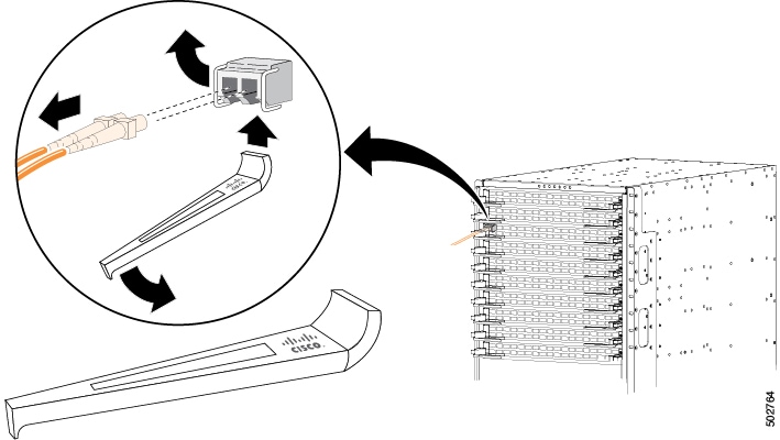
Prevent damage to the fiber-optic cables that can separate from their cables. Keep the transceivers disconnected from their fiber-optic cables when installing the transceiver in the line card. Before removing such a transceiver from the switch, remove the cable from the transceiver.

To maximize the effectiveness and life of your transceivers and optical cables:

  • Wear an ESD-preventative wrist strap that is connected to an earth ground whenever handling transceivers. The switch is typically grounded during installation and provides an ESD port to which you can connect your wrist strap.

  • Do not remove and insert a transceiver more often than is necessary. Repeated removals and insertions can shorten its useful life.

  • Keep the transceivers and fiber-optic cables clean and dust free to maintain high signal accuracy and to prevent damage to the connectors. Contamination causes increased attenuation (loss of light), and should be kept below 0.35 dB.

    • Clean these parts before installation to prevent dust from scratching the fiber-optic cable ends.

    • Clean the connectors regularly; the required frequency of cleaning depends upon the environment. In addition, clean connectors if they are exposed to dust or accidentally touched. Both wet and dry cleaning techniques can be effective; refer to your site's fiber-optic connection cleaning procedures.

    • Do not touch the ends of connectors. Touching the ends can leave fingerprints and cause other contamination.

  • Inspect routinely for dust and damage. If you suspect damage, clean and then inspect fiber ends under a microscope to determine if damage has occurred.

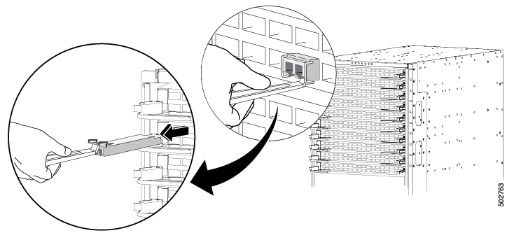
  • To minimize the chance of damaging transceivers when installing them, slide them gently into their switch slots. Never force transceivers all the way into the slots. If the transceiver stops part way into the slot, it might be upside down. Remove the transceiver before turning it over and reinstalling it. If positioned correctly, the transceiver slides all the way into the slot and clicks when fully installed.


Warning


Statement 1051—Laser Radiation

Invisible laser radiation may be emitted from disconnected fibers or connectors. Do not stare into beams or view directly with optical instruments.


Warning


Statement 1055—Class 1/1M Laser

Invisible laser radiation is present. Do not expose to users of telescopic optics. This applies to Class 1/1M laser products.


Warning


Statement 1056—Unterminated Fiber Cable

Invisible laser radiation may be emitted from the end of the unterminated fiber cable or connector. Do not view directly with optical instruments. Viewing the laser output with certain optical instruments, for example, eye loupes, magnifiers, and microscopes, within a distance of 100 mm, may pose an eye hazard.


Connecting a Console to the Switch

Before you create a network management connection for the switch or connect the switch to the network, create a local management connection through a console terminal. Then configure an IP address for the switch. Use the console to perform these functions, each of which can be performed through the management interface after you make that connection.

  • Configure the switch using the command-line interface (CLI).

  • Monitor network statistics and errors.

  • Configure Simple Network Management Protocol (SNMP) agent parameters.

  • Download software updates.

Make this local management connection between the asynchronous serial port on a supervisor module and a console device capable of asynchronous transmission. Typically, you use a computer terminal as the console device. On the supervisor modules, use the console serial port.


Note


Before you can connect the console port to a computer terminal, make sure that the computer terminal supports VT100 terminal emulation. The terminal emulation software makes communication between the switch and the computer possible during setup and configuration.


Before you begin

  • The switch must be fully installed in its rack, connected to a power source, and grounded.

  • The necessary cabling for the console, management, and network connections must be available.

    • An RJ-45 rollover cable and DB9F/RJ-45 adapter are provided in the switch accessory kit.

    • Network cabling is routed to the location of the installed switch.

Procedure


Step 1

Configure the console device to match these default port characteristics:

  • 9600 baud

  • 8 data bits

  • 1 stop bit

  • No parity

Step 2

Connect an RJ-45 rollover cable to the console port on the switch.

Find this cable in the accessory kit.

Step 3

Route the RJ-45 rollover cable to the console or a modem.

Step 4

Connect the other end of the RJ-45 rollover cable to the console or to a modem.

If the console or modem cannot use an RJ-45 connection, use the DB-9F/RJ-45F PC terminal adapter, found in the accessory kit for the switch. Alternatively, you can use an RJ-45/DSUB F/F or RJ-45/DSUB RP adapter, but you must provide those adapters.


What to do next

Create the initial switch configuration. See Creating the Initial Switch Configuration.

Connecting the Management Interface

The supervisor management port (MGMT ETH) provides out-of-band management, which enables you to use the command-line interface (CLI) to manage the switch by its IP address. This port uses a 10/100/1000 Ethernet connection with an RJ-45 interface.


Note


In a dual supervisor switch, you can ensure that the active supervisor module is always connected to the network by connecting the management interface on both supervisor modules to the network. Perform this task for each supervisor module. No matter which supervisor module is active, the switch automatically has a management interface that is running and accessible from the network.


Caution


To prevent an IP address conflict, do not connect the management port until the initial configuration is complete. For more information, see Creating the Initial Switch Configuration.


Before you begin

You must have completed the initial switch configuration. See Creating the Initial Switch Configuration).

Procedure


Step 1

Connect a modular, RJ-45, UTP cable to the MGMT ETH port on the supervisor module.

Step 2

Route the cable through the central slot in the cable management system.

Step 3

Connect the other end of the cable to a 10/100/1000 Ethernet port on a network device.


What to do next

Connect the interface ports on each of the line cards to the network.

Creating the Initial Switch Configuration

Before you begin

  • A console device must be connected with the switch.

  • The switch must be connected to a power source.

  • Determine the IP address and the netmask that is needed for the Management (Mgmt0) interface.

Procedure


Step 1

Power up the switch by connecting each installed power supply to an AC circuit.

If you are using the input-source (n+n) power mode, connect half of the power supplies to one AC circuit. Connect the other half of the power supplies to another AC circuit.

The Input and Output LEDs on each power supply light up (green) when the power supply units are sending power to the switch. The software asks you to specify a password to use with the switch.

Step 2

Enter a new password for this switch.

The software checks the security strength of your password. It rejects your password if it does not meet these guidelines:

  • At least eight characters.

  • Minimizes or avoids the use of consecutive characters (such as "abcd").

  • Minimizes or avoids repeating characters (such as "aaabbb").

  • Does not contain recognizable words from the dictionary.

  • Does not contain proper names.

  • Contains both uppercase and lowercase characters.

  • Contains numbers and letters.

Examples of strong passwords are:

  • If2CoM18

  • 2004AsdfLkj30

  • Cb1955S21

Note


Clear text passwords cannot include the dollar sign ($) special character.

Tip


If a password is trivial (such as a short, easy-to-decipher password), the software will reject your password configuration. Configure a strong password as explained in this step. Passwords are case-sensitive.

When you enter a strong password, the software asks you to confirm the password.

Step 3

Enter the same password again.

If you enter the same password, the software accepts the password and begins asking a series of configuration questions.

Step 4

Until you are asked for an IP address, enter the default configuration for each question.

Repeat this step for each question until you are asked for the Mgmt0 IPv4 address.

Step 5

Enter the IP address for the management interface.

The software asks for the Mgmt0 IPv4 netmask.

Step 6

Enter a network mask for the management interface.

The software asks if you need to edit the configuration.

Step 7

Enter no, to not edit the configuration.

The software asks if you need to save the configuration.

Step 8

Enter yes to save the configuration.


What to do next

Set up the management interface for each supervisor module on the switch.

Connecting Interface Ports

Connect BASE-T (copper) and optical interface ports on line cards with other devices for connectivity to the network.

Connecting a BASE-T Port to the Network

Connect a line-card BASE-T (copper) port to another device on the network using a copper network interface cable with RJ-45 connectors on either end.

Before you begin

  • Follow the ESD-preventative protocol, such as wearing a grounded ESD wrist strap, whenever handling electronic components.

  • You must have BASE-T ports available for connection on a line card that is installed on the switch.

  • You must have BASE-T ports available on another networked device, which can be another switch.

Procedure


Step 1

Route the copper interface cable from the other networking device to the switch. At the switch, route the cable through the cable management slot next to the line card that you are connecting.

Step 2

Insert the RJ-45 connector for the new interface cable into the appropriate port on the line card.

Check the port LED to be sure that it turns on and turns green.


Disconnecting a BASE-T Port from the Network

Disconnect a BASE-T (copper) port from the network by removing a copper network interface cable with RJ-45 connectors from the line card interface port.

Before you begin

Follow the ESD-preventative protocol, such as wearing a grounded ESD wrist strap, whenever handling electronic components.

Procedure


Step 1

Remove the RJ-45 connector from the interface port that you are disconnecting on the line card.

The port LED turns off.

Step 2

(Optional) Remove the interface cable from the device on the other end of the cable.


Connecting an Optical Port to the Network

Depending on the type line card that you are using, use a 1-Gigabit SFP, 10-Gigabit SFP+, 25-Gigabit SFP28, 40-Gigabit QSFP+, 100-Gigabit CFP2, QSFP28, or QSFP-DD transceivers. Some of these transceivers work with fiber-optic cables that you attach to the transceivers and other transceivers work with preattached copper cables. To prolong the life of detachable transceivers, install the transceivers before installing the fiber-optic cable in the transceivers.


Note


The N9K-X9536PQ line card supports your use of SFP and SFP+ transceivers in QSFP+ ports when using a QSFP-to-SFP adapter, such as the CVS-QSFP-SFP10G adapter.


Caution


Removing and installing a transceiver can shorten its useful life. Do not remove and insert transceivers more often than is necessary. We recommend that you disconnect cables before installing or removing transceivers to prevent damage to the cable or transceiver.


Procedure


Step 1

If there is a protective cover for the port that you are connecting, remove the protective covering.

Step 2

For the transceiver that you are inserting into a port:

  1. If the transceiver is connected to an optical cable, remove the cable from the transceiver.

  2. Insert the transceiver into the open port.

  3. If using an optical cable, insert the optical cable into the installed transceiver.

Step 3

To install the other end of the cable into another device:

  1. If the transceiver is connected to an optical cable, remove the cable from the transceiver.

  2. Insert the transceiver into the open port.

  3. If using an optical cable, insert the optical cable into the installed transceiver.


Disconnecting Optical Ports from the Network

When removing fiber-optic transceivers, remove the fiber-optic cables from a transceiver before removing the transceiver from the port.

Optic Transceiver Removal Using the Optics Extraction Tool

Use both ends of the optics extraction tool in this procedure. Use the wide end for releasing the bale latch and the narrow end for removing the transceiver module.

Before you begin

Before you handle any switch components, attach a grounded electrostatic discharge (ESD) strap. To ground the strap, attach it directly to earth ground or to a grounded rack or chassis. There must be a metal-to-metal connection to earth ground.

Procedure


Step 1

Remove the fiber-optic cables from the transceiver module before removing the transceiver module.

Step 2

Use the wide side of the optics extraction tool to release the bale latch (see the figure).

Step 3

Use the narrow end of the optics extraction tool to carefully remove the transceiver module (see the figure).

Step 4

Place the transceiver module in an antistatic bag or other protective environment.


Maintaining Transceivers and Optical Cables

Keep transceivers and fiber-optic cables clean and dust free to maintain high signal accuracy and prevent damage to the connectors. Contamination increases attenuation (loss of light) and should be below 0.35 dB.

Consider these maintenance guidelines:

  • Transceivers are static sensitive. To prevent ESD damage, wear an ESD-preventative wrist strap that is connected to the grounded chassis.

  • Do not remove and insert a transceiver more often than is necessary. Repeated removals and insertions can shorten its useful life.

  • Keep all optical connections covered when not in use. Clean them before using to prevent dust from scratching the fiber-optic cable ends.

  • Do not touch the ends of connectors. Touching the ends can leave fingerprints and cause other contamination.

  • Clean the connectors regularly; the required frequency of cleaning depends upon the environment. In addition, clean connectors if they are exposed to dust or accidentally touched. Both wet and dry cleaning techniques can be effective; refer to the fiber-optic connection cleaning procedures for your site.

  • Inspect routinely for dust and damage. If you suspect damage, clean and then inspect fiber ends under a microscope to determine if damage has occurred.


Note


If cable length is more than 5 meters, Auto Negotiation is not supported.


Note


The N9K-X9436PQ, N9K-X9564PX, and N9K-X9564TX line cards do not support Link Training.


Note


When you need to remove a fiber-optic transceiver, first remove the fiber-optic cable from the transceiver before you remove the transceiver from the port.