Overview
The Cisco N9348Y2C6D-SE1U switch (N9348Y2C6D-SE1U) is a 1-rack unit (RU), top of rack (TOR) fixed-port switch designed for deployment in data centers. It has 48 QSFP28 ports used for 25G operation on the front panel.
This switch includes data processing units (DPUs) to handle data processing, front port traffic, security, and other software functions. The DPUs functions can be turned off to conserve power when certain software services are not activated.
This switch includes these ports:
-
48 x 1/10/25-Gigabit Ethernet SFP28 ports (ports 1-48).
-
6 x 400 GE (QSFP-DD) ports (ports 51-56)
-
2 x 40/100 GE (QSFP28) ports, (ports 49-50)
-
2 x SFP 1/10 G Management port
-
1 Management port (one 10/100/1000 BASE-T port)
-
1 Console port (RS-232)
-
1 x USB 3.0 port
This switch supports the following combinations of user-replaceable components:
-
Port-side Intake (PI): 6 NXA-SFAN-35CFM-PI fans and 2 NXA-PAC-1100W-PI2 PSUs
-
Port-side Exhaust (PE): 6 NXA-SFAN-35CFM-PE fans and 2 NXA-PAC-1100W-PE2 PSUs
Fans
Each fan module has two rotors. Fan speed (RPM) is controlled by system software based on the system cooling algorithm. This switch supports “Track Fan” modules and system software can read the Series Number information from the fan modules for tracking purpose.
This switch runs with 1+1 redundancy mode, so that if one fan fails, the switch can sustain operation. But if a second fan fails, this switch is not designed to sustain operation. Before waiting to reach major threshold temperature, the switch will power down due to Powered-down due to fan policy trigger.
Each fan module has two rotors. The switch can function normally if one rotor inside any one fan module fails. In case of more than one rotor failure, the switch issues a warning and powers down in 2 minutes.
Power Supply Units
Power supply modules (two—One for operations and one for redundancy [1+1]) with this choice:
-
1100-W port-side intake AC power supply with burgundy coloring (NXA-PAC-1100W-PI2)
-
1100-W port-side exhaust AC power supply with blue coloring (NXA-PAC-1100W-PE2)
-
1100-W port-side intake DC power supply with burgundy coloring (NXA-PDC-1100W-PI)
-
1100-W port-side intake HV power supply with burgundy coloring (NXA-PHV-1100W-PI)
 Note |
|
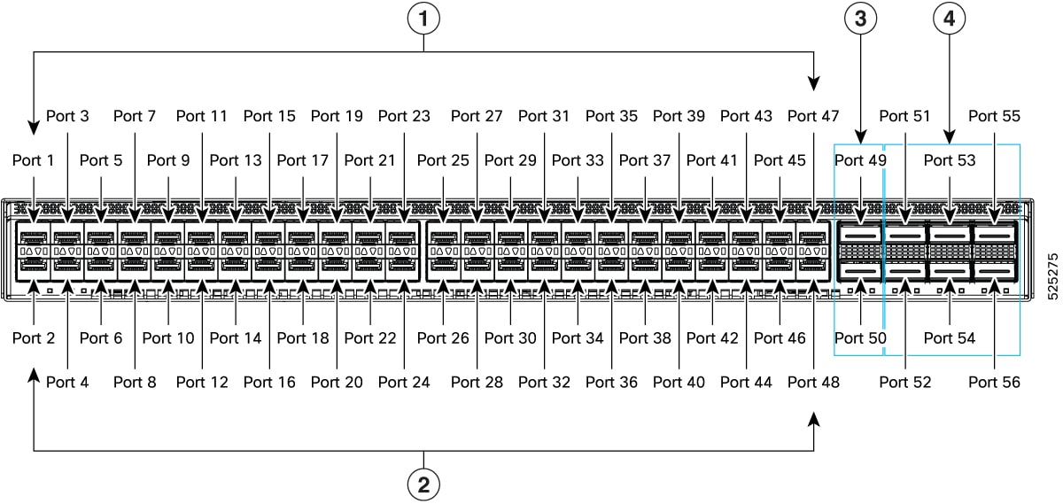
The figure shows the switch features on the front side of the chassis.
|
1 |
24 x 1/10/25G ports. Odd numbered ports: P1, P3, P5, P7, etc. |
3 |
Ports 49 and 50: QSFP28 100G ethernet Uplink ports |
|
2 |
24 x 1/10/25G ports. Even numbered ports: P2, P4, P6, P8, etc. |
4 |
Ports 51-56: DD-QSFP56 400G ethernet Uplink ports |
To determine which transceivers, adapters, and cables support this switch, see the Cisco Transceiver Modules Compatibility Information document.
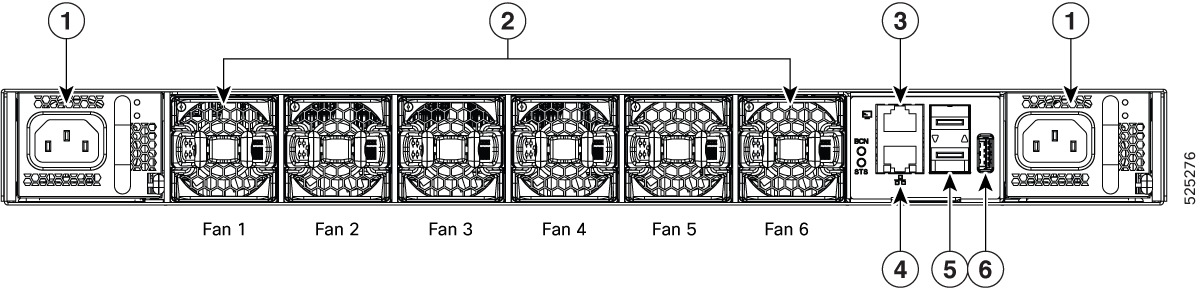
The figure shows the switch features on the power supply side of the chassis, the back view.
|
1 |
Power supply modules (1 or 2) (AC power supplies shown) with slots numbered 1 (left) and 2 (right) |
4 |
Management port (RJ45) |
|
2 |
Fan modules (6) with slots numbered from 1 (left) to 6 (right) |
5 |
2 x 10 G SFP ports |
|
3 |
Console port |
6 |
3.0 USB port |
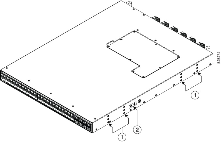
The figure shows the side of the chassis.
|
1 |
Screw holes for mounting brackets |
2 |
Grounding pad |
Depending on whether you plan to position the ports in a hot or cold aisle, order the fan and power supply modules with port-side intake or port-side exhaust airflow. For port-side intake airflow, the fan and power supplies have burgundy/red coloring. For port-side exhaust airflow, the fan and power supplies have blue coloring.
The fan and power supply modules are field replaceable. Replace one fan module or one power supply module during operations as long as the other modules are installed and operating. If you have only one power supply installed, install the replacement power supply in the open slot before removing the original power supply.
Note |
All fan and power supply modules must have the same direction of airflow. Otherwise, the switch can overheat and shut down. |
 Caution |
If the switch has port-side intake airflow (burgundy coloring for fan modules), locate the ports in the cold aisle. If the switch has port-side exhaust airflow (blue coloring for fan modules), locate the ports in the hot aisle. If you locate the air intake in a hot aisle, the switch can overheat and shut down. |
 Feedback