Overview
The Cisco Nexus 9332PQ switch (N9K-C9332PQ) is a 1 rack unit (RU) switch that supports 26 40-Gigabit QSFP+ downlink ports (ports 1 to 12 and 15 to 26 support the Dynamic Breakout cabling), 6 40-Gigabit QSFP+ uplink ports, one 100/1000 network management ports, one RS-232 console port for setting the initial switch configuration, and two USB ports for saving or loading switch configurations.
 Note |
Beginning with Cisco ACI Release 12.2, you can use 40-Gigabit to 4X10-Gigabit breakout cables with the downlink ports 1 to 12 and 15 to 26. |
The chassis for this switch includes the following user-replaceable components:
-
Fan modules (four) with the following airflow choices:
-
Port-side intake fan module with burgundy coloring (NXA-FAN-30CFM-B)
-
Port-side exhaust fan module with blue coloring (NXA-FAN-30CFM-F)
-
-
Power supplies (two—one for operations and one for redundancy [1+1]) with the following choices:
-
650-W AC power supply with port-side intake airflow (burgundy coloring) (N9K-PAC-650W)
-
650-W AC power supply with port-side exhaust airflow (blue coloring) (N9K-PAC-650W-B)
-
930-W DC power supply with port-side intake airflow (green coloring) (UCSC-PSU-930WDC)
-
930-W DC power supply with port-side exhaust airflow (gray coloring) (UCS-PSU-6332-DC)
Note
Do not mix AC and DC power supplies in the same chassis.
Note
All fan modules and power supplies must use the same airflow direction during operations.
-
The switch supports the Fabric Extenders (FEXs) listed at https://www.cisco.com/c/en/us/td/docs/switches/datacenter/nexus9000/hw/interoperability/fexmatrix/fextables.html.
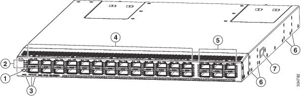
The following figure shows the switch features on the port side of the chassis.
|
1 |
Port lane switch button |
5 |
40-Gigabit QSFP+ spine-facing ports (6) |
|
2 |
Port lane LEDs |
6 |
Screw holes for mounting brackets |
|
3 |
Beacon (BCN), Status (STS), and Environment (ENV) LEDs |
7 |
Grounding pad |
|
4 |
40-Gigabit QSFP+ APIC-facing interface ports (26). Ports 1 to 12 and 15 to 26 also support 40-Gigabit-to-4x10-Gigabit breakout cables with the Dynamic Breakout feature. |
To determine which transceivers, adapters, and cables are supported by this switch, see the Cisco Transceiver Modules Compatibility Information document.
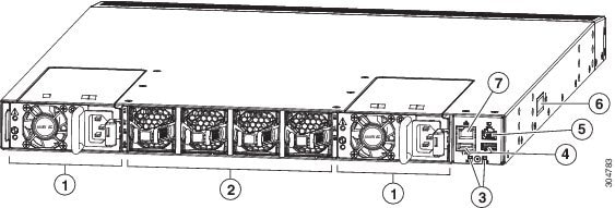
The following figure shows the switch features on the power supply side of the chassis.
|
1 |
Power supply modules (1 or 2) (AC power supply shown) with slots numbered from 1 (left) to 4 (right). |
5 |
Console port (1) |
|
2 |
Fan modules (4) with slots numbered 1 (left) and 2 (right). |
6 |
Grounding pad |
|
3 |
Beacon (BCN) and Status (STS) LEDs |
7 |
Management port (1) |
|
4 |
USB ports (2) |
Depending on whether you plan to position the ports in a hot or cold aisle, you can order the fan and power supply modules with port-side intake or port-side exhaust airflow. For port-side intake airflow, the fan and AC power supply modules have burgundy coloring (DC power supply modules have green coloring). For port-side exhaust airflow, the fan and AC power supplies have blue coloring (DC power supply modules have gray coloring).
The fan and power supply modules are field replaceable and you can replace one fan module or one power supply module during operations so long as the other modules are installed and operating. If you have only one power supply installed, you can install the replacement power supply in the open slot before removing the original power supply.
Note |
All of the fan and power supply modules must have the same direction of airflow. Otherwise, the switch can overheat and shut down. If you are installing a dual-direction power supply, that module will automatically use the same airflow direction as the other modules in the switch. |
 Caution |
If the switch has port-side intake airflow (burgundy coloring for fan modules), you must locate the ports in the cold aisle. If the switch has port-side exhaust airflow (blue coloring for fan modules), you must locate the ports in the hot aisle. If you locate the air intake in a hot aisle, the switch can overheat and shut down. |
 Feedback