Configuring PVLAN over OTV

This chapter describes the Configuring PVLAN over OTV feature on Cisco NX-OS devices.

Information About Configuring PVLAN over OTV

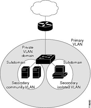
The private VLAN (PVLAN) partitions the Layer 2 Ethernet broadcast domain of a VLAN into subdomains, allowing you to isolate the ports on the switch from each other. A subdomain consists of a primary VLAN and one or more secondary VLANs (see the following figure). All VLANs in a PVLAN domain share the same primary VLAN. For more information about PVLANs, see Configuring Private VLANs Using NX-OS chapter in Cisco Nexus 7000 Series NX-OS Layer 2 Switching Configuration Guide.

Figure 1. Private VLAN Domain

Beginning from Release 8.2(1), Cisco Nexus 7000 Series Switches support Private VLAN (PVLAN) extended over the OTV overlay. The transmission occurs in a Layer2 frame attached to a Layer 3 header. Over the OTV overlay, this feature allows two VLANs to communicate based on the PVLAN association.

PVLAN provides L2 port isolation by breaking a VLAN up into sub-domains. Primary VLAN or uplink can communicate with all the Secondary VLANs in its domain. Secondary VLANs communicates to an uplink Primary (P) VLAN and then the communication between secondary VLANs themselves can be isolate or community configurations as follows:

  • Isolated (I)-they only communicate with the uplink and do not communicate with other hosts on the same 2nd VLAN.

  • Community (C)-ports on this VLAN can talk among themselves and the uplink.

After the OTV is configured, and PVLAN primary and secondary VLANs are configured, OTV will receive a message from the VLAN manager that describe these PVLAN configurations.

In a multi-homing configuration, OTV will split the VLANs as odd and even between the two edge devices. In the route look-up table, the VLAN of the MAC from the secondary VLAN is the primary VLAN ID.

In OTV ARP cache the MAC is associated with the original VLAN ID, and therefore OTV is aware of the VLAN type. Based on the VLAN type, OTV decides whether an ARP request should be responded.

For example:

  • If an ARP request is coming from an isolated VLAN, OTV will only response if the MAC is found in its primary VLAN.

  • If an ARP request is coming from a community VLAN, OTV will only response if the MAC is found on that community VLAN ID and its primary VLAN.

  • If an ARP request is coming from a primary VLAN ID, OTV will response if the MAC is found on the primary VLAN ID all its secondary VLANs.

Prerequisites for Configuring PVLAN over OTV

  • PVLAN must be configured on the Datacenter Edge device and OTV overlay device.

Default Settings for PVLAN over OTV

There are no default settings for this feature.

Guidelines and Limitations for PVLAN over OTV

  • Starting from Cisco NX-OS Release 8.4(1) this feature is supported on F4 Series modules.

  • This feature is limited to Cisco Nexus 7000 Series and Nexus 7700 Series Switches, F3, F4, and M3 modules only.

  • This feature is limited to 1500 PVLAN's extended (Primary and Secondary VLAN's counted).

    VLAN translation is not supported, if the VLAN ID is associated with the PVLAN feature.

    The secondary VLANs will have the same AED as that of their primary VLAN.

  • OTV supports MAC movement. If a host is hopping from VLAN 1 to VLAN2, OTV ARP table will delete the old entry on VLAN1 and insert the new one on VLAN 2.

    OTV Flood MAC can be configured on primary VLANs only, and not on Secondary VLANs.

    Although flood mac is configured on primary VLAN only, the MAC will also be flooded as if it appears on secondary VLAN.

Configuring PVLAN over OTV

To configure PVLAN over OTV perform the following steps:

Procedure


Step 1

Enter the Global Configuration mode.

switch# configure terminal

Step 2

Create an overlay interface and enters interface configuration mode.

switch(config)# interface overlay interface

Step 3

Extend the primary PVLAN over this overlay interface and enable OTV advertisements for these VLANs.

switch(config-if-overlay)# otv extend-vlan vlan-range


Example: Configuring PVLAN over OTV

This example shows a running configuration, followed by a verification command that displays the Cisco PVLAN over OTV configuration details. Replace the placeholders with relevant values for your setup.

The example shows how to configure the PVLAN over OTV, with OTV extended over VLAN ID 100, and associated to 101-103.

Configure PVLAN.

configure terminal
feature pvlan

vlan 100
    private-vlan primary
    private-vlan association 101-103
vlan 101
    private-vlan community
vlan 102
    private-vlan community
vlan 103
    private-vlan isolated

Extend primary PVLAN over the overlay to configure PVLAN over OTV.


    configure terminal
    feature otv

    interface overlay 1
    otv extend-vlan 100

Verifying Configuring PVLAN over OTV

Use the following commands to display PVLAN configuration information.

Command

Purpose

switch# show otv vlan private-vlan

Displays the association of private VLAN to the PVLAN over OTV.

switch# show otv arp-nd-cache private-vlan

Displays the address mapping for remote MAC addresses on the PVLAN interface

switch# show otv route

Displays the OTV unicast MAC routing table for the Overlay.

To view the PVLAN over OTV configuration, use the following show commands.

switch# show otv vlan private-vlan

OTV Extended VLANs and Edge Device State Information (* - AED)

Legend:
(NA) - Non AED, (VD) - Vlan Disabled, (OD) - Overlay Down
(DH) - Delete Holddown, (HW) - HW: State Down, (NFC) - Not Forward Capable

VLAN       Auth. Edge Device       Vlan State       Overlay
------     ------------------      -----------      ---------
100*       N77K-2-OTV11            active           Overlay1
           Primary (101-103 (count 3))
101*       N77K-2-OTV11            active           Overlay1
           Community (100)
102*       N77K-2-OTV11            active           Overlay1
           Community (100)
103*       N77K-2-OTV11            active           Overlay1
           Isolated (100)
switch# show otv arp-nd-cache private-vlan

OTV ARP/ND L3->L2 Address Mapping Cache
Overlay Interface Overlay1
(P) - Primary PVLAN, (I) - Isolated PVLAN, (C) - Community PVLAN
VLAN      MAC Address       Layer-3 Address    Age        Expires In
101  (C)  aaaa.aaaa.aaa4    100.100.100.21     00:04:36   00:03:23
103  (I)  aaaa.aaaa.aaa5    100.100.100.21     00:03:24   00:04:35
switch# show otv route
OTV Unicast MAC Routing Table For Overlay1

VLAN   MAC-Address       Metric    Uptime      Owner       Next-hop(s)
----   --------------    ------    -------     -------     -------------
100    8c60.4fe8.2a42    1         00:08:25     site       port-channel120
100    8c60.4fe8.2a48    42        00:42:00     overlay    N77K-2-OTV21
100    aaaa.aaaa.aaa4    42        00:19:51     overlay    N77K-2-OTV21
100    aaaa.aaaa.aaa5    42        00:42:00     overlay    N77K-2-OTV21
100    aaaa.aaaa.aaaf    0         00:42:00     static     Overlay1

Feature Information for Configuring PVLAN over OTV

The following table provides release information about the feature or features described in this module. This table lists only the software release that introduced support for a given feature in a given software release train. Unless noted otherwise, subsequent releases of that software release train also support that feature.

Use Cisco Feature Navigator to find information about platform support and Cisco software image support. To access Cisco Feature Navigator, go to https://cfnng.cisco.com/. An account on Cisco.com is not required.
Table 1. Feature Information for Configuring PVLAN over OTV

Feature Name

Releases

Feature Information

Configuring PVLAN over OTV

8.4(1)

Added support for F4 Series modules.

Configuring PVLAN over OTV

8.2(1)

This feature was introduced.