Cisco Plug-in for OpenFlow

Cisco Plug-in for OpenFlow, Release 2.0.2 provides better control over networks making them more open, programmable, and application-aware and supports the following specifications defined by the Open Networking Foundation (ONF) standards organization:

  • OpenFlow Switch Specification Version 1.0.1 (Wire Protocol 0x01) (referred to as OpenFlow 1.0)

  • OpenFlow Switch Specification Version 1.3.0 (Wire Protocol 0x04) (referred to as OpenFlow 1.3).

This chapter contains the following sections:

Licensing Requirements

For a complete explanation of Cisco NX-OS licensing recommendations and how to obtain and apply licenses, see the Cisco NX-OS Licensing Guide.

Prerequisites for Cisco Plug-in for OpenFlow

  • A Cisco device and its corresponding operating system that supports the installation of Cisco Plug-in for OpenFlow.


    Note

    A compatibility matrix is delivered with each Cisco application. Refer to this matrix for information about the operating system releases that support features and infrastructure necessary for a particular application, such as Cisco Plug-in for OpenFlow.


  • An open virtual application (OVA) package that is compatible with the device operating system and downloaded from an FTP server connected to the device.

  • A controller installed on a connected server.

    Table 1. Controller Support

    OpenFlow Version

    Supported Controllers

    OpenFlow 1.0

    Extensible Network Controller (XNC) 1.0, POX, or Ixia controllers

    OpenFlow 1.0

    Cisco Nexus Data Broker (NDB) 2.1.0

    OpenFlow 1.3

    Ixia or OpenDaylight

  • The required disk storage available on the device for installation and deployment of Cisco Plug-in for OpenFlow. Recommended disk space per Virtual Device Context (VDC) is 700 MB.

Restrictions for Cisco Plug-in for OpenFlow

  • You cannot configure a bridge domain, Virtual LANs, and virtual routing and forwarding (VRF) interfaces on a Cisco Plug-in for OpenFlow logical switch.

  • Cisco Plug-in for OpenFlow is not supported on default VDC.

  • OpenFlow hybrid switch Integrated model is not supported. OpenFlow hybrid switch (ships-in-the-night) model is supported with physical port separation with virtual device contexts (VDCs). OpenFlow and non-OpenFlow ports must be configured on different VDCs.

  • Reachability to controller via Switched Virtual Interface (SVI) is not supported.

  • A routing and switching protocol must not be enabled on interfaces that are allocated to OpenFlow VDCs.

  • You cannot configure more than 3000 flows in an OpenFlow VDC.

Information About Cisco Plug-in for OpenFlow

Cisco Plug-in for OpenFlow Feature Support

The following is a subset of OpenFlow 1.3 functions that are supported by Cisco Plug-in for OpenFlow.

Supported Feature

Additional Notes

OpenFlow-hybrid switch (ships-in-the-night) type is supported using OpenFlow 1.3 packet format with limitations.

OpenFlow hybrid (ships-in-the-night) hybrid model is supported with physical port seperation on virtual device contexts (VDCs). OpenFlow can be enabled on a subset of devices and ports making a part of the network OpenFlow enabled while the rest of the network continues to run using traditional forwarding principles. But the OpenFlow and non-OpenFlow ports of a device must be configured on different VDCs.

OpenFlow hybrid (integrated) switch type is not supported.

Dedicated virtual device context (VDC) for OpenFlow

  • OpenFlow can be enabled and installed on up to seven dedicated VDCs if the device has the required space.

  • Physical interfaces in Layer 2 and Layer 3 mode assigned to the VDC must be configured as Cisco Plug-in for OpenFlow logical switch ports.

  • A non default VDC must be used for OpenFlow.

Connection to up to eight controllers.

  • Each Cisco Plug-in for OpenFlow VDC can connect to one controller. You can connect to up to eight controllers using seven VDCS.
  • Connection is via TCP.

  • All controllers of a VDC should be running the same OpenFlow version (1.3 or lower).

Pipelines for Cisco Plug-in for OpenFlow logical switch

  • Pipelines are mandatory for the logical switch.
  • The logical switch supports the following pipelines:
    • Pipeline 321 supports the L2 MAC forwarding table.
    • Pipeline 322 supports the IPv4 and IPv6 forwarding, ARP, and L2 MAC forwarding tables.

Ethertype selector based table lookup

Ethertype of a packet decides the forwarding table and the corresponding match and action criteria. Ethertype is mandatory for pipeline 322.

Supported Interface Types

Physical interfaces and port-channel interfaces.

L2 Forwarding Table (Ethertype = *) (Pipeline 321)

Supported match criteria:

  • Source MAC address

  • Destination MAC address

  • Ethernet type (inner only)
  • Input port

  • VLAN priority code point
  • VLAN ID (with restrictions)
Note 
If a packet contains a VLAN tag (Ethertype 0x8100), the outer Ethertype is ignored and the match is done using the VLAN ID, VLAN priority, or Inner Ethertype.
Supported action criteria:
  • Output to multiple ports (supports up to 8 ports)

  • Output to controller
  • Set VLAN ID

  • Strip VLAN ID

  • Drop

IPv4 Forwarding Table (Ethertype = 0x800) (Pipeline 322)

Supported match criteria:

  • Ethertype (mandatory)
  • IP protocol
  • Source IP address (IPv4)
  • Destination IP address (IPv4)
  • Layer 4 source port (TCP or UDP)
  • Layer 4 destination port (TCP or UDP)
  • Input port

Supported action criteria:

  • Output to multiple ports (supports up to 8 ports)
  • Punt to controller
    Note 

    Punt to controller cannot be combined with any modify actions.

  • Set source MAC address (SMAC)
  • Set destination MAC address (DMAC)
  • Set VLAN ID
  • Strip VLAN ID
  • Drop

IPv6 Forwarding Table (Ethertype = 0x86DD) (Pipeline 322)

Supported match criteria:

  • Ethertype (mandatory)
  • IP protocol
  • Source IP address (IPv6)
  • Destination IP address (IPv6))
  • Layer 4 source port (TCP or UDP)
  • Layer 4 destination port (TCP or UDP)
  • Input port

Supported action criteria:

  • Output to multiple ports (supports up to 8 ports)
  • Punt to controller
    Note 

    Punt to controller cannot be combined with any modify actions.

  • Set source MAC address (SMAC)
  • Set destination MAC address (DMAC)
  • Set VLAN ID
  • Strip VLAN ID
  • Drop

ARP Table (Ethertype = 0x806) (Pipeline 322)

Supported match criteria:

  • Ethertype (mandatory)
  • Input port

Supported action criteria:

  • Output to multiple ports (supports up to 8 ports)
  • Punt to controller
  • Drop

Default Action

If packets do not match flows of any of the tables above, the default action for each table is drop.

You can also configure the default action and set it to controller if required.

OpenFlow v1.3 message types

The “modify state” and “queue config” message types are not supported. All other message types are supported.

Multiple actions

Flows defined on the controller must follow the guidelines below:
  • Multiple VLAN actions are not possible.
  • The flow should not have multiple rewrite actions that override one another the last action is effective. For example, strip VLAN after set VLAN or multiple set VLANs.

  • You cannot combine an output to port action with a punt to controller or drop action.

OpenFlow 1.3 counters

Per Port—Received Packets, Transmitted Packets, Received Bytes, Transmitted Bytes, Receive Drops, Transmit Drops, Receive Errors, Transmit Errors, Receive Frame Alignment Errors, Receive Overrun Errors, Collisions, Duration (in seconds), Duration (in nanoseconds).

Note 
Per Flow and Per Table counters are not supported.

About OpenFlow

OpenFlow Switch Specification Version 1.0.1 (Wire Protocol 0x01) (referred to as OpenFlow 1.0) and OpenFlow Switch Specification Version 1.3.0 (Wire Protocol 0x04), referred to as OpenFlow 1.3, is based on the concept of an Ethernet switch, with an internal flow table and standardized interface to allow traffic flows on a device to be added or removed. OpenFlow 1.3 defines the communication channel between Cisco Plug-in for OpenFlow and controllers.

Cisco Plug-in for OpenFlow 2.0.2 refers to Cisco Plug-in for OpenFlow, Release 2.0.2.

A controller can be Extensible Network Controller (XNC) 1.0, or any controller compliant with OpenFlow 1.3.

In an OpenFlow network, Cisco Plug-in for OpenFlow exists on the device and controllers exist on a server, that is external to the device. Flow management and any network management are either part of a controller or accomplished through a controller. Flow management includes the addition, or removal of flows, and the handling of OpenFlow 1.3 error messages.

The following figure gives an overview of the OpenFlow network.

Figure 1. OpenFlow Overview


Cisco Plug-in for OpenFlow Operation

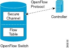
Cisco Plug-in for OpenFlow creates OpenFlow–based TCP/IP connections to controllers for a Cisco Plug-in for OpenFlow logical switch. Cisco Plug-in for OpenFlow creates databases for a configured logical switch, OpenFlow-enabled interfaces, and flows. The logical switch database contains all the information needed to connect to a controller. The interface database contains the list of OpenFlow-enabled interfaces associated with a logical switch, and the flow database contains the list of flows on a logical switch as well as for interface that is programmed into forwarded traffic.

OpenFlow Controller Operation

OpenFlow controller (referred to as controller) controls the switch and inserts flows with a subset of OpenFlow 1.3 and 1.0 match and action criteria through Cisco Plug-in for OpenFlow logical switch. Cisco Plug-in for OpenFlow rejects all OpenFlow messages with any other action.

Cisco Plug-in for OpenFlow and Virtual Services Container

Cisco Plug-in for OpenFlow runs in an operating–system–level virtual service container on the device. The Cisco Plug-in for OpenFlow virtual service container is delivered in an open virtual application (OVA) file package (.ova). The OVA package is installed and enabled on the device through the CLI.

How to Configure Cisco Plug-in for OpenFlow

This section includes the following required and optional tasks. All tasks below require the fulfillment of the prerequisites listed in Prerequisites for Cisco Plug-in for OpenFlow:

Configuring Physical Device Parameters

This section contains the following:

Configuring Global Variables for a Cisco Plug-in for OpenFlow Logical Switch

Before you begin

Create a non default VDC for Cisco Plug-in for OpenFlow.

SUMMARY STEPS

  1. switchto vdc openflow-vdc-id
  2. configure terminal
  3. no cdp enable
  4. vlan {vlan-id | vlan-range}
  5. end
  6. copy running-config startup-config

DETAILED STEPS

  Command or Action Purpose
Step 1

switchto vdc openflow-vdc-id

Example:
Device# switchto vdc openflow

Switch to the OpenFlow VDC.

Step 2

configure terminal

Example:
Device# configure terminal

Enters global configuration mode.

Step 3

no cdp enable

Example:
Device(config)# no cdp enable

Disables Cisco Discovery Protocol (CDP).

Step 4

vlan {vlan-id | vlan-range}

Example:
Device(config)# vlan 1-512

Adds a VLAN or VLAN range for interfaces on the device and enters the VLAN configuration mode.

Step 5

end

Example:
Device(config-vlan)# exit

Exits VLAN configuration mode and enters privileged EXEC mode.

Step 6

copy running-config startup-config

Example:
Device# copy running-config startup-config

Saves the change persistently through reboots and restarts by copying the running configuration to the startup configuration.

What to do next

Specify a route to the controller.

Specifying a Route to a Controller

The following tasks are used to specify a route from the device to a controller. This can be done using a physical interface (Front Panel) or a management interface.

The IP address of the controller is configured in the Configuring a Cisco Plug-in for OpenFlow Logical Switch section.

Specifying a Route to a Controller Using a Physical Interface

SUMMARY STEPS

  1. switchto vdc openflow-vdc-id
  2. configure terminal
  3. interface type number
  4. no switchport
  5. ip address ip-address mask
  6. exit
  7. ip route 0.0.0.0 0.0.0.0 next-hop
  8. exit
  9. copy running-config startup-config

DETAILED STEPS

  Command or Action Purpose
Step 1

switchto vdc openflow-vdc-id

Example:
Device# switchto vdc openflow

Switch to the OpenFlow VDC.

Step 2

configure terminal

Example:
Device# configure terminal

Enters global configuration mode.

Step 3

interface type number

Example:
Device(config)# interface Ethernet2/2

Configures the physical interface. The interface used here should not be a Cisco Plug-in for OpenFlow ports.

Step 4

no switchport

Example:
Device(config-if)# no switchport

Configures a specified interface as a Layer 3 interface and deletes any interface configuration specific to Layer 2.

Step 5

ip address ip-address mask

Example:
Device(config-if)# ip address 10.0.1.4 255.255.255.0

Configures an IP address for a specified interface.

Step 6

exit

Example:
Device(config-if)# exit

Exits interface configuration mode and enters global configuration mode.

Step 7

ip route 0.0.0.0 0.0.0.0 next-hop

Example:
Device(config)# ip route 0.0.0.0 0.0.0.0 10.0.1.6

Configures a default route for packet addresses not listed in the routing table. Packets are directed toward a controller.

Step 8

exit

Example:
Device(config)# exit

Exits global configuration mode and enters privileged EXEC mode.

Step 9

copy running-config startup-config

Example:
Device# copy running-config startup-config

Saves the changes persistently by copying the running configuration to the startup configuration.

What to do next

Configure interfaces for the Cisco Plug-in for OpenFlow logical switch.

Specifying a Route to a Controller Using a Management Interface

SUMMARY STEPS

  1. switchto vdc openflow-vdc-id
  2. configure terminal
  3. interface mgmt management-interface-name number
  4. ip address ip-address mask
  5. exit
  6. vrf context management
  7. ip route 0.0.0.0 0.0.0.0 next-hop
  8. exit
  9. copy running-config startup-config

DETAILED STEPS

  Command or Action Purpose
Step 1

switchto vdc openflow-vdc-id

Example:
Device# switchto vdc openflow

Switch to the OpenFlow VDC.

Step 2

configure terminal

Example:
Device# configure terminal

Enters global configuration mode.

Step 3

interface mgmt management-interface-name number

Example:
Device(config)# interface mgmt0

Enters the management interface.

Step 4

ip address ip-address mask

Example:
Device(config-if)# ip address 10.0.1.4 255.255.255.0

Configures an IP address for the interface.

Step 5

exit

Example:
Device(config-if)# exit

Exits interface configuration mode and enters global configuration mode.

Step 6

vrf context management

Example:
Device(config)# vrf context management

Configures the management Virtual routing and forwarding (VRF) instance and enters in VRF configuration mode.

Step 7

ip route 0.0.0.0 0.0.0.0 next-hop

Example:
Device(config-vrf)# ip route 0.0.0.0 0.0.0.0 10.0.1.6

Configures a default route for packet addresses not listed in the routing table. Packets are directed toward a controller.

Step 8

exit

Example:
Device(config)# exit

Exits global configuration mode and enters privileged EXEC mode.

Step 9

copy running-config startup-config

Example:
Device# copy running-config startup-config

Saves the change persistently by copying the running configuration to the startup configuration.

What to do next

Configure interfaces for the Cisco Plug-in for OpenFlow logical switch.

Configuring Interfaces for a Cisco Plug-in for OpenFlow Logical Switch

You must configure physical interfaces before the interfaces are added as ports of a Cisco Plug-in for OpenFlow logical switch. These interfaces are added as ports of the Cisco Plug-in for OpenFlow logical switch in the Configuring a Cisco Plug-in for OpenFlow Logical Switch section.

Configuring a Physical Interface in Layer 2 mode

Perform the following task to add a physical interface to a Cisco Plug-in for OpenFlow logical switch in Layer 2 mode.

SUMMARY STEPS

  1. switchto vdc openflow-vdc-id
  2. configure terminal
  3. interface Ethernetslot port
  4. switchport
  5. switchport mode trunk
  6. mac packet-classify
  7. switchport mode trunk allowed vlan [vlan-list]
  8. spanning-tree port type edge trunk
  9. no shutdown
  10. end
  11. copy running-config startup-config

DETAILED STEPS

  Command or Action Purpose
Step 1

switchto vdc openflow-vdc-id

Example:
Device# switchto vdc openflow

Switch to the OpenFlow VDC.

Step 2

configure terminal

Example:
Device# configure terminal

Enters global configuration mode.

Step 3

interface Ethernetslot port

Example:
Device(config)# interface Ethernet2/2

Specifies the interface for the logical switch and enters interface configuration mode.

Step 4

switchport

Example:
Device(config-if)# switchport

Specifies an interface as a Layer 2 port.

Step 5

switchport mode trunk

Example:
Device(config-if)# switchport mode trunk

Specifies an interface as a trunk port.

  • A trunk port can carry traffic of one or more VLANs on the same physical link. (VLANs are based on the trunk-allowed VLANs list.) By default, a trunk interface carries traffic for all VLANs.

  • This command is enabled only if the switchport command has been configured.

Step 6

mac packet-classify

Example:
Device(config-if)# mac packet-classify

Enables MAC packet classification on the interface.

Step 7

switchport mode trunk allowed vlan [vlan-list]

Example:
Device(config-if)# switchport trunk allowed vlan 1-3

Sets the list of allowed VLANs that transmit traffic from this interface in tagged format when in trunking mode.

Step 8

spanning-tree port type edge trunk

Example:
Device(config-if)# spanning-tree port type edge trunk

Enables edge behavior on the trunk port.

  • This command is enabled only if the switchport command has been configured.

Step 9

no shutdown

Example:
Device(config-if)# no shutdown

Enables the interface.

Step 10

end

Example:
Device(config-if)# end

Exits interface configuration mode and enters privileged EXEC mode.

Step 11

copy running-config startup-config

Example:
Device# copy running-config startup-config

Saves the change persistently by copying the running configuration to the startup configuration.

What to do next

Repeat these steps to configure any additional interfaces for a Cisco Plug-in for OpenFlow logical switch. Once all the interfaces are configured, install and activate Cisco Plug-in for OpenFlow.

Configuring a Physical Interface in Layer 3 mode

Perform the task below to add a physical interface to a Cisco Plug-in for OpenFlow logical switch in Layer 3 mode.

SUMMARY STEPS

  1. switchto vdc openflow-vdc-id
  2. configure terminal
  3. interface type slot/port
  4. no shutdown
  5. end
  6. copy running-config startup-config

DETAILED STEPS

  Command or Action Purpose
Step 1

switchto vdc openflow-vdc-id

Example:
Device# switchto vdc openflow

Switch to the OpenFlow VDC.

Step 2

configure terminal

Example:
Device# configure terminal

Enters global configuration mode.

Step 3

interface type slot/port

Example:
Device(config)# interface Ethernet1/1
Device(config)# interface port-channel 101

Specifies the interface for the logical switch and enters interface configuration mode.

Step 4

no shutdown

Example:
Device(config-if)# no shutdown

Enables the interface.

Step 5

end

Example:
Device(config-if)# end

Exits interface configuration mode and enters privileged EXEC mode.

Step 6

copy running-config startup-config

Example:
Device# copy running-config startup-config

Saves the change persistently by copying the running configuration to the startup configuration.

What to do next

Repeat these steps to configure any additional interfaces for a Cisco Plug-in for OpenFlow logical switch. Once all the interfaces are configured, install and activate Cisco Plug-in for OpenFlow.

Configuring a Subinterface in Layer 3 mode

Perform the task below to configure one or more subinterfaces on a routed interface or on a port channel made from routed interfaces to a Cisco Plug-in for OpenFlow logical switch in Layer 3 mode.

SUMMARY STEPS

  1. switchto vdc openflow-vdc-id
  2. configure terminal
  3. interface type slot/port-number
  4. encapsulation dot1Q vlan-id
  5. no shutdown
  6. end
  7. copy running-config startup-config

DETAILED STEPS

  Command or Action Purpose
Step 1

switchto vdc openflow-vdc-id

Example:

Device# switchto vdc openflow

Switch to the OpenFlow VDC.

Step 2

configure terminal

Example:

Device# configure terminal

Enters global configuration mode.

Step 3

interface type slot/port-number

Example:

Device(config)# interface Ethernet4/13.1

Creates a subinterface and enters subinterface configuration mode. The valid range is from 1 to 4094.

Step 4

encapsulation dot1Q vlan-id

Example:

Device(config-subif)# encapsulation dot1Q 501

Configures IEEE 802.1Q VLAN encapsulation on the subinterface. The valid range is from 1 to 3967.

Step 5

no shutdown

Example:

Device(config-subif)# no shutdown

Enables the interface.

Step 6

end

Example:

Device(config-subif)# end

Exits interface configuration mode and enters privileged EXEC mode.

Step 7

copy running-config startup-config

Example:

Device# copy running-config startup-config

Saves the change persistently by copying the running configuration to the startup configuration.

What to do next

Verify Cisco Plug-in for OpenFlow.

Installing and Activating Cisco Plug-in for OpenFlow

Cisco Plug-in for OpenFlow is an application that runs at the operating–system-level virtual services container on a device. Cisco Plug-in for OpenFlow is delivered in an open virtual application (OVA) package. The OVA package is installed and activated on the device through the CLI.

You must switch to the non default VDC that was created and enabled for Cisco Plug-in for OpenFlow in order to install the OVA package You can enable and install Cisco Plug-in for OpenFlow on up to three dedicated VDCs if the device has required space. slot0: of the Nexus 7000 series device must be used for kickstart and system images.

Before installing and activating Cisco Plug-in for OpenFlow, ensure that an OVA package compatible with the device exists on a connected FTP server. Refer to the Prerequisites for a Virtual Services Container. A reload of the device is not essential after installing, uninstalling, or upgrading Cisco Plug-in for OpenFlow software.

To install and activate Cisco Plug-in for OpenFlow software, refer to the instructions in Installing and Activating an Application in a Virtual Services Container, where the virtual services application argument, virtual-services-name , can be specified as openflow_plugin.

To uninstall and deactivate Cisco Plug-in for OpenFlow software, refer to the instructions in Deactivating and Uninstalling an Application from a Virtual Services Container, where the virtual services application argument, virtual-services-name , must be the same as that specified during installation.

To upgrade Cisco Plug-in for OpenFlow software, refer to the instructions in Upgrading an Application in a Virtual Services Container, where the virtual services application argument, virtual-services-name , must be the same as that specified during installation.

Once installed, configure a Cisco Plug-in for OpenFlow logical switch.

Configuring a Cisco Plug-in for OpenFlow Logical Switch

This task configures a Cisco Plug-in for OpenFlow logical switch and the IP address of a controller.

SUMMARY STEPS

  1. switchto vdc openflow-vdc-id
  2. configure terminal
  3. openflow
  4. switch logical-switch-id
  5. pipeline pipeline-id
  6. Do one of the following:
    • of-port interface interface-name
    • of-port interface port-channel-name
  7. protocol-version version-info
  8. controller ipv4 ip-address [port tcp-port] [ vrf vrf-name] security{none | tls}
  9. default-miss { drop | controller }
  10. (Optional) logging flow-mod
  11. (Optional) probe-interval probe-interval
  12. (Optional) rate-limit packet_in controller-packet-rate burst maximum-packets-to-controller
  13. (Optional) max-backoff backoff-timer
  14. end
  15. copy running-config startup-config

DETAILED STEPS

  Command or Action Purpose
Step 1

switchto vdc openflow-vdc-id

Example:

Device# switchto vdc openflow

Switches to the specified VDC.

Step 2

configure terminal

Example:

Device# configure terminal

Enters global configuration mode.

Step 3

openflow

Example:

Device(config)# openflow

Enters Cisco Plug-in for OpenFlow mode.

Step 4

switch logical-switch-id

Example:

Device(config-ofa)# switch 1

Specifies an ID for a logical switch that is used for Layer 2 (default) switching operations and enters logical switch configuration mode.

  • The only logical switch ID supported is 1.

Step 5

pipeline pipeline-id

Example:

Device(config-ofa-switch)# pipeline 321

Configures a pipeline .

  • This step is mandatory for a logical switch configuration.
  • You can view the supported pipeline values using the show openflow hardware capabilities command.
  • The valid values are from 321 and 322.

Step 6

Do one of the following:

  • of-port interface interface-name
  • of-port interface port-channel-name

Example:

For a physical interface:
Device(config-ofa-switch)# of-port interface ethernet1/1
For a port-channel interface:
Device(config-ofa-switch)# of-port interface port-channel2
Configures an Ethernet interface or port-channel interface as a port of a Cisco Plug-in for OpenFlow logical switch.
  • Do not abbreviate the interface type. Ensure that the interface type is spelled out completely and is as shown in the examples. If the keyword is abbreviated, the interface is not configured. The interface type must be in lowercase.

  • The interface must be designated for the Cisco Plug-in for OpenFlow logical switch only.

  • The mode openflow configuration is added to an interface when an interface is configured as a port of Cisco Plug-in for OpenFlow. To add or remove an interface as a port of Cisco Plug-in for OpenFlow, ensure that the Cisco Plug-in for OpenFlow is activated and running to ensure the proper automatic addition and removal of the mode openflow configuration. To remove an interface as a port of Cisco Plug-in for OpenFlow, use the no form of this command.

  • Repeat this step to configure additional interfaces.

Step 7

protocol-version version-info

Example:

Device(config-openflow-switch)# protocol-version 1.0

Configures the protocol version.

  • Supported values are:

    • 1.0 —Configures device to connect to 1.0 controllers only

    • 1.3 —Configures device to connect to 1.3 controllers only

    • negotiate—Negotiates the protocol version with the controller. Device uses 1.3 for negotiation.

    Note 

    The default value is negotiate.

  • drop is the default action for both tables or pipeline 1. This can be overridden by this configuration or the controller.
Step 8

controller ipv4 ip-address [port tcp-port] [ vrf vrf-name] security{none | tls}

Example:

Controller in default VRF:
Device(config-openflow-switch)# controller ipv4 10.1.1.2 security none
Controller in management VRF:
Device(config-ofa-switch)# controller ipv4 10.1.1.2 vrf management security none
Specifies the IPv4 address, port number, and VRF of a controller that can manage the logical switch, port number used by the controller to connect to the logical switch and the VRF of the controller.
  • If unspecified, the default VRF is used.

  • Controllers use TCP port 6653 by default.

  • You can configure up to eight controllers. Repeat this step if you need to configure additional controllers.

  • If TLS is not disabled in this step, configure TLS trustpoints in the next step.

  • You can use the clear openflow switch 1 controller all command to clear controller connections. This command can reset a connection after Transport Layer Security (TLS) certificates and keys are updated. This is not required for TCP connections.

A connection to a controller is initiated for the logical switch.

Step 9

default-miss { drop | controller }

Example:

Device(config-ofa-switch)# default-miss controller

Configures the action to be taken for packets that do not match any of the flow defined.

  • drop is the default action for a pipeline.
Step 10

(Optional) logging flow-mod

Example:

Device(config-ofa-switch)# logging flow-mod
(Optional)

Enables logging of flow changes, including addition, deletion, and modification of flows.

  • Logging of flow changes is disabled by default.
  • Flow changes are logged in syslog and can be viewed using the show logging command.
  • Logging of flow changes is a CPU intensive activity and should not be enabled for networks greater than 1000 flows.
Step 11

(Optional) probe-interval probe-interval

Example:

Device(config-openflow-switch)# probe-interval 5
(Optional)

Configures the interval, in seconds, at which the controller is probed.

  • The default value is 5.

  • The range is from 5 to 65535.

Step 12

(Optional) rate-limit packet_in controller-packet-rate burst maximum-packets-to-controller

Example:

Device(config-openflow-switch)# rate-limit packet_in 1 burst 4
(Optional)

Configures the maximum packet rate of the connection to the controller and the maximum packets permitted in a burst of packets sent to the controller in a second.

  • The default value is zero, meaning that an indefinite packet rate and packet burst are permitted.

  • This rate limit is for Cisco Plug-in for OpenFlow. It is not related to the rate limit of the device (data plane) configured by COPP.

Step 13

(Optional) max-backoff backoff-timer

Example:

Device(config-openflow-switch)# max-backoff 8
(Optional)

Configures the time, in seconds, for which the device must wait before attempting to initiate a connection with the controller.

  • The default value is eight.

  • The range is from 1 to 65535.

Step 14

end

Example:

Device(config-openflow-switch)# end

Exits logical switch configuration mode and enters privileged EXEC mode.

Step 15

copy running-config startup-config

Example:

Device# copy running-config startup-config

Saves the change persistently by copying the running configuration to the startup configuration.

What to do next

Verify Cisco Plug-in for OpenFlow.

Verifying Cisco Plug-in for OpenFlow

SUMMARY STEPS

  1. show openflow copyright
  2. show openflow switch switch-id
  3. show openflow switch switch-id controllers [stats]
  4. show openflow switch switch-id ports [hidden]
  5. show openflow switch switch-id flows [table-id table-id][configured | controller | default | fixed | pending | pending-del] [ brief | summary]
  6. show openflow switch switch-id stats
  7. show interfaces type number counters
  8. show logging last number-of-lines
  9. show running-config | section openflow
  10. show openflow hardware capabilities

DETAILED STEPS


Step 1

show openflow copyright

Displays copyright information related to Cisco Plug-in for OpenFlow.

Example:

Device# show openflow copyright 

Cisco Plug-in for OpenFlow
TAC support: http://www.cisco.com/tac
Copyright (c) 2013-2015 by Cisco Systems, Inc. All rights reserved.
The copyrights to certain works contained in this software are
owned by other third parties and used and distributed under
license. Certain components of this software are licensed under
the GNU General Public License (GPL) version 2.0, the GNU
Lesser General Public License (LGPL) Version 2.1, or or the GNU
Library General Public License (LGPL) Version 2. A copy of each
such license is available at
http://www.opensource.org/licenses/gpl-2.0.php and
http://www.opensource.org/licenses/lgpl-2.1.php and
http://www.gnu.org/licenses/old-licenses/lgpl-2.0.txt
Step 2

show openflow switch switch-id

Displays information related to Cisco Plug-in for OpenFlow logical switch.

Example:

Device# show openflow switch 1 

Logical Switch Context
  Id: 1
  Switch type: Forwarding
  Pipeline id: 321
  Data plane: secure
  Table-Miss default: controller
  Configured protocol version: OF protocol 1.0
  Config state: no-shutdown
  Working state: enabled
  Rate limit (packet per second): 1
  Burst limit: 4
  Max backoff (sec): 8
  Probe interval (sec): 5
  TLS local trustpoint name: not configured
  TLS remote trustpoint name: not configured
  Logging flow changes: Enabled
  Stats collect interval (sec): 0
  Stats collect Max flows: 0
  Stats collect period (sec): disabled
  Minimum flow idle timeout (sec): disabled
  OFA Description:
    Manufacturer: Cisco Systems, Inc.
    Hardware: N7K-C7010 V01
    Software: 7.2(0)D1(1) of_agent 0.1
    Serial Num: TBM13384460
    DP Description: N7K_OFA_2:sw1
  OF Features:
    DPID:000100269801ccc1
    Number of tables:1
    Number of buffers:256
    Capabilities: PORT_STATS
 Controllers:
    5.30.26.111:6800, Protocol: TCP, VRF: management
    10.1.1.2:6653, Protocol: TCP, VRF: default
    10.1.1.2:6653, Protocol: TCP, VRF: management
  Interfaces:
    port-channel2
    port-channel7
    Ethernet2/2
    Ethernet2/4
    Ethernet2/5
Step 3

show openflow switch switch-id controllers [stats]

Displays information related to the connection status between an Cisco Plug-in for OpenFlow logical switch and connected controllers.

Example:


Device# show openflow switch 1 controllers 

Logical Switch Id: 1
Total Controllers: 3
  Controller: 1
    10.1.1.2:6653
    Protocol: tcp
    VRF: default
    Connected: No
    Role: Master
    Negotiated Protocol Version: disconnected
    Last Alive Ping: N/A
    last_error:No route to host
    state:BACKOFF

  Controller: 2
    5.30.26.111:6800
    Protocol: tcp
    VRF: management
    Connected: No
    Role: Master
    Negotiated Protocol Version: disconnected
    Last Alive Ping: N/A
    last_error:Connection timed out
    state:CONNECTING
    sec_since_disconnect:14

  Controller: 3
    10.1.1.2:6653
    Protocol: tcp
    VRF: management
    Connected: No
    Role: Master
    Negotiated Protocol Version: disconnected
    Last Alive Ping: N/A
    last_error:Connection timed out
    state:CONNECTING
    sec_since_disconnect:13

The above sample output is displayed when controller is not yet connected.

Device# show openflow switch 1 controllers stats 

Logical Switch Id: 1
Total Controllers: 3
  Controller: 1
    address                         :  tcp:10.1.1.2:6653
    connection attempts             :  3009
    successful connection attempts  :  0
    flow adds                       :  0
    flow mods                       :  0
    flow deletes                    :  0
    flow removals                   :  0
    flow errors                     :  0
    flow unencodable errors         :  0
    total errors                    :  0
    echo requests                   :  rx: 0, tx: 0
    echo reply                      :  rx: 0, tx: 0
    flow stats                      :  rx: 0, tx: 0
    barrier                         :  rx: 0, tx: 0
    packet-in/packet-out            :  rx: 0, tx: 0

  Controller: 2
    address                         :  tcp:5.30.26.111:6800%management
    connection attempts             :  1506
    successful connection attempts  :  0
    flow adds                       :  0
    flow mods                       :  0
    flow deletes                    :  0
    flow removals                   :  0
    flow errors                     :  0
    flow unencodable errors         :  0
    total errors                    :  0
    echo requests                   :  rx: 0, tx: 0
    echo reply                      :  rx: 0, tx: 0
    flow stats                      :  rx: 0, tx: 0
    barrier                         :  rx: 0, tx: 0
    packet-in/packet-out            :  rx: 0, tx: 0

  Controller: 3
    address                         :  tcp:10.1.1.2:6653%management
    connection attempts             :  1506
    successful connection attempts  :  0
    flow adds                       :  0
    flow mods                       :  0
    flow deletes                    :  0
    flow removals                   :  0
    flow errors                     :  0
    flow unencodable errors         :  0
    total errors                    :  0
    echo requests                   :  rx: 0, tx: 0
    echo reply                      :  rx: 0, tx: 0
    flow stats                      :  rx: 0, tx: 0
    barrier                         :  rx: 0, tx: 0
    packet-in/packet-out            :  rx: 0, tx: 0
Step 4

show openflow switch switch-id ports [hidden]

Displays the mapping between physical device interfaces and ports of an Cisco Plug-in for OpenFlow logical switch.

Example:

Device# show openflow switch 1 ports

Logical Switch Id: 1
Port  Interface Name    Config-State   Link-State     Features
1002  Po2               PORT_UP        LINK_DOWN      100MB-HD
1007  Po7               PORT_UP        LINK_UP        1GB-HD
5097  Eth2/5            PORT_UP        LINK_DOWN      10GB-FD
5098  Eth2/4            PORT_UP        LINK_DOWN      10GB-FD
5099  Eth2/2            PORT_UP        LINK_DOWN      10GB-FD
Step 5

show openflow switch switch-id flows [table-id table-id][configured | controller | default | fixed | pending | pending-del] [ brief | summary]

Displays flows defined for the device by controllers.

Example:

Device# show openflow switch 1 flows

Logical Switch Id: 1
Total flows: 1

Flow: 1
  Match:             any
  Actions:           CONTROLLER:0
  Priority:          0
  Table:             0
  Cookie:            0x0
  Duration:          25466.484s
  Number of packets: 0
  Number of bytes:   0
Device# show openflow switch 1 flows configured 

Logical Switch Id: 1
Total flows: 1

Flow: 1
  Match:             
  Actions:           drop
  Priority:          0
  Table:             0
  Cookie:            0x0
  Duration:          1937.586s
  Number of packets: 0
  Number of bytes:   0


Device# show openflow switch 1 flows fixed 

Logical Switch Id: 1
Total flows: 0

Step 6

show openflow switch switch-id stats

Displays send and receive statistics for each port defined for a Cisco Plug-in for OpenFlow logical switch.

Example:

Device# show openflow switch 1 stats

Logical Switch Id: 1

Total ports: 5
  Port 1002: rx pkts=0, bytes=0, drop=0, errs=0,
           tx pkts=0, bytes=0, drop=0, errs=0,
  Port 5098: rx pkts=0, bytes=0, drop=0, errs=0,
           tx pkts=0, bytes=0, drop=0, errs=0,
  Port 1007: rx pkts=9447, bytes=3012905, drop=0, errs=0,
           tx pkts=0, bytes=0, drop=0, errs=0,
  Port 5097: rx pkts=0, bytes=0, drop=0, errs=0,
           tx pkts=0, bytes=0, drop=0, errs=0,
  Port 5099: rx pkts=0, bytes=0, drop=0, errs=0,
           tx pkts=0, bytes=0, drop=0, errs=0,
Total tables: 1
  Table 0: NXOS PLCMGR LAYER2
  Wildcards = 0x3fffff
  Max entries =   3000
  Active entries = 0
  Number of lookups = 18446744073709551615
  Number of matches = 18446744073709551615
Step 7

show interfaces type number counters

Displays send and receive statistics for the specified port defined for an Cisco Plug-in for OpenFlow logical switch.

Example:

Device# show interfaces Ethernet 2/1 counters detailed

Ethernet2/1
  Rx Packets:                                       47053
  Rx Unicast Packets:                                5802
  Rx Multicast Packets:                             23908
  Rx Broadcast Packets:                             17343
  Rx Bytes:                                      12202848
  Rx Packets from 0 to 64 bytes:                    16323
  Rx Packets from 65 to 127 bytes:                  14247
  Rx Packets from 256 to 511 bytes:                  7053
  Rx Packets from 512 to 1023 bytes:                 7674
  Rx Packets from 1024 to 1518 bytes:                1756
  Rx Trunk Packets:                                   512
  Tx Packets:                                         261
  Tx Multicast Packets:                               259
  Tx Broadcast Packets:                                 2
  Tx Bytes:                                         61503
  Tx Packets from 0 to 64 bytes:                        2
  Tx Packets from 128 to 255 bytes:                   259
  Layer 3 Multicast Input Packets                   11817
  Layer 3 Multicast Input Bytes                   1057668

Device# show interfaces Ethernet 2/1 counters 


--------------------------------------------------------------------------------
Port                                 InOctets                      InUcastPkts
--------------------------------------------------------------------------------
Eth2/2                                      0                                0

--------------------------------------------------------------------------------
Port                              InMcastPkts                      InBcastPkts
--------------------------------------------------------------------------------
Eth2/2                                      0                                0

--------------------------------------------------------------------------------
Port                                OutOctets                     OutUcastPkts
--------------------------------------------------------------------------------
Eth2/2                                      0                                0

--------------------------------------------------------------------------------
Port                             OutMcastPkts                     OutBcastPkts
--------------------------------------------------------------------------------
Eth2/2                                      0                                0
Step 8

show logging last number-of-lines

Displays logging information of flow changes, including addition, deletion or modification of flows.

Example:

Device# show logging last 14

2013 Mar 15 19:13:05 n3k-202-194-4 %VMAN-2-ACTIVATION_STATE: Successfully activa
ted virtual service 'n3k'
2013 Mar 15 19:13:23 n3k-202-194-4 %VMAN-5-VIRT_INST: VIRTUAL SERVICE n3k LOG: E
rror: Didn't get initial config when booting up
2013 Mar 15 19:13:50 n3k-202-194-4 %VMAN-5-VIRT_INST: VIRTUAL SERVICE n3k LOG: O
VS: Flows flushed for sw1, type:cisco-l2
2013 Mar 15 19:13:54 n3k-202-194-4 %VSHD-5-VSHD_SYSLOG_CONFIG_I: Configured from
 vty by admin on console0
2013 Mar 15 19:14:09 n3k-202-194-4 %VMAN-5-VIRT_INST: VIRTUAL SERVICE n3k LOG: O
VS: Flow created: Rule: ip,dl_vlan=3 Actions: output:2,output:7
2013 Mar 15 19:14:09 n3k-202-194-4 %VMAN-5-VIRT_INST: VIRTUAL SERVICE n3k LOG: O
VS: Flow created: Rule: ip,dl_vlan=4 Actions: output:2,output:7
2013 Mar 15 19:14:09 n3k-202-194-4 %VMAN-5-VIRT_INST: VIRTUAL SERVICE n3k LOG: O
VS: Flow created: Rule: ip,dl_vlan=5 Actions: output:2,output:7
2013 Mar 15 19:14:09 n3k-202-194-4 %VMAN-5-VIRT_INST: VIRTUAL SERVICE n3k LOG: O
VS: Flow created: Rule: ip,dl_vlan=6 Actions: output:2,output:7
2013 Mar 15 19:14:09 n3k-202-194-4 %VMAN-5-VIRT_INST: VIRTUAL SERVICE n3k LOG: O
VS: Flow created: Rule: ip,dl_vlan=7 Actions: output:2,output:7
2013 Mar 15 19:14:09 n3k-202-194-4 %VMAN-5-VIRT_INST: VIRTUAL SERVICE n3k LOG: O
VS: Flow created: Rule: ip,dl_vlan=8 Actions: output:2,output:7
2013 Mar 15 19:14:09 n3k-202-194-4 %VMAN-5-VIRT_INST: VIRTUAL SERVICE n3k LOG: O
VS: Flow created: Rule: ip,dl_vlan=9 Actions: output:2,output:7
2013 Mar 15 19:14:09 n3k-202-194-4 %VMAN-5-VIRT_INST: VIRTUAL SERVICE n3k LOG: O
VS: Flow created: Rule: ip,dl_vlan=10 Actions: output:2,output:7
2013 Mar 15 19:14:09 n3k-202-194-4 %VMAN-5-VIRT_INST: VIRTUAL SERVICE n3k LOG: O
VS: Flow created: Rule: ip,dl_vlan=11 Actions: output:2,output:7
2013 Mar 15 19:14:09 n3k-202-194-4 %VMAN-5-VIRT_INST: VIRTUAL SERVICE n3k LOG: O
VS: Flow created: Rule: ip,dl_vlan=12 Actions: output:2,output:7

Device# show logging last 14

2015 Jun 26 03:18:02 N7K_OFA_2 %VMAN-5-VIRT_INST_NOTICE: VIRTUAL SERVICE ofa LOG
: Error: Calling sdna_watchdog_run
2015 Jun 26 03:18:10 N7K_OFA_2 %VMAN-5-VIRT_INST_NOTICE: VIRTUAL SERVICE ofa LOG
: last message repeated 26 times.
2015 Jun 26 03:18:10 N7K_OFA_2 %VMAN-5-VIRT_INST_NOTICE: VIRTUAL SERVICE ofa LOG
: OVS: sw1<->tcp:10.1.1.2:6653: connection failed (No route to host)
2015 Jun 26 03:18:10 N7K_OFA_2 %VMAN-5-VIRT_INST_NOTICE: VIRTUAL SERVICE ofa LOG
: Error: Calling sdna_watchdog_run
2015 Jun 26 03:18:19 N7K_OFA_2 %VMAN-5-VIRT_INST_NOTICE: VIRTUAL SERVICE ofa LOG
: last message repeated 26 times.
2015 Jun 26 03:18:19 N7K_OFA_2 %VMAN-5-VIRT_INST_NOTICE: VIRTUAL SERVICE ofa LOG
: OVS: sw1<->tcp:10.1.1.2:6653: connection failed (No route to host)
2015 Jun 26 03:18:19 N7K_OFA_2 %VMAN-5-VIRT_INST_NOTICE: VIRTUAL SERVICE ofa LOG
: Error: Calling sdna_watchdog_run
2015 Jun 26 03:18:26 N7K_OFA_2 %VMAN-5-VIRT_INST_NOTICE: VIRTUAL SERVICE ofa LOG
: last message repeated 32 times.
2015 Jun 26 03:18:26 N7K_OFA_2 %VMAN-5-VIRT_INST_NOTICE: VIRTUAL SERVICE ofa LOG
: OVS: sw1<->tcp:10.1.1.2:6653: connection failed (No route to host)
2015 Jun 26 03:18:26 N7K_OFA_2 %VMAN-5-VIRT_INST_NOTICE: VIRTUAL SERVICE ofa LOG
: Error: Calling sdna_watchdog_run
Step 9

show running-config | section openflow

Displays configurations made for Cisco Plug-in for OpenFlow.

Example:

Device# show running-config | section openflow

openflow
  switch 1
    protocol-version 1.0
    pipeline 321
    default-miss controller
    logging flow-mod
    rate-limit packet_in 1 burst 4
    max-backoff 8
    probe-interval 5
    controller ipv4 10.1.1.2 port 6653 security none
    controller ipv4 5.30.26.111 port 6800 vrf management security none
    controller ipv4 10.1.1.2 port 6653 vrf management security none
    of-port interface ethernet2/2
    of-port interface ethernet2/4
    of-port interface ethernet2/5
    of-port interface port-channel2
    of-port interface port-channel7
Step 10

show openflow hardware capabilities

Displays Cisco Plug-in for OpenFlow configurations.

Example:

Device# show openflow hardware capabilities
 
 Pipeline ID: 321

    Pipeline Max Flows: 0

    Pipeline Default Statistics Collect Interval: 0

    Flow table ID: 0

    Max Flow Batch Size: 150
    Max Flows: 3000
    Bind Subintfs: FALSE
    Primary Table: TRUE
    Table Programmable: TRUE
    Miss Programmable: TRUE
    Number of goto tables: 0
    goto table id:
    Stats collection: Not Supported

    Match Capabilities                  Match Types
    ------------------                  -----------
    ethernet mac destination            lengthmask
    ethernet mac source                 lengthmask
    ethernet type                       optional
    VLAN ID                             optional
    VLAN priority code point            optional
    in port (virtual or physical)       optional
    wildcard all matches                optional

    Actions                     Count Limit             Order
    specified interface                 8               20
    controller                          1               20

    set vlan id                         1               10

    pop vlan tag                        1               10

    drop packet                         1               20
    Miss actions                        Count Limit             Order
    specified interface                 8               20
    controller                          1               20

    set vlan id                         1               10

    pop vlan tag                        1               10

    drop packet                         1               20


  Max Flow Batch Size: 150

  Statistics Max Polling Rate (flows/sec): 1024

  Max Interfaces: 1000

  Aggregated Statistics: NO

  Pipeline ID: 322

    Pipeline Max Flows: 0

    Pipeline Default Statistics Collect Interval: 0

    Flow table ID: 0

    Max Flow Batch Size: 150
    Max Flows: 3000
    Bind Subintfs: FALSE
    Primary Table: TRUE
    Table Programmable: FALSE
    Miss Programmable: TRUE
    Number of goto tables: 4
    goto table id:      1 2 3 4
    Stats collection: Not Supported

    Match Capabilities                  Match Types
    ------------------                  -----------
    ethernet type                       mandatory

    Actions                     Count Limit             Order
    perform another lookup in the specified table       1               20


    Miss actions                        Count Limit             Order
    perform another lookup in the specified table       1               20

.
.
.

Configuration Examples for Cisco Plug-in for OpenFlow

Example: Configuring Global Variables for a Cisco Plug-in for OpenFlow Logical Switch

Device# switchto vdc openflow-
Device# configure terminal
Device(config)# no cdp enable
Device(config)# vlan 1-512
Device(config-vlan)# end
Device# copy running-config startup-config

Example: Specifying a Route to a Controller Using a Physical Interface

Device# switchto vdc openflow
Device# configure terminal
Device(config)# interface Ethernet2/2
Device(config-if)# no switchport
Device(config-if)# ip address 10.0.1.4 255.255.255.255
Device(config-if)# exit
Device(config)# ip route 0.0.0.0 0.0.0.0 10.0.1.6
Device# copy running-config startup-config
Device(config)# exit

Example: Specifying a Route to a Controller Using a Management Interface

Device# switchto vdc openflow
Device# configure terminal
Device(config)# interface mgmt0
Device(config-if)# no switchport
Device(config-if)# ip address 10.0.1.4 255.255.255.255
Device(config-if)# exit
Device(config)# ip route 0.0.0.0 0.0.0.0 10.0.1.6
Device(config)# exit
Device# copy running-config startup-config

Example: Installing and Activating Cisco Plug-in for OpenFlow

Refer to Installing and Activating an Application in a Virtual Services Container for an example of installing and activating Cisco Plug-in for OpenFlow in a virtual services container of a device.

Example: Configuring an Interface for a Cisco Plug-in for OpenFlow Logical Switch in L2 mode

Device# switchto vdc openflow
Device# configure terminal
Device(config)# interface ethernet1/1
Device(config-if)# switchport
Device(config-if)# switchport mode trunk
Device(config-if)# mac packet-classify
Device(config-if)# switchport trunk allowed vlan 1-3
Device(config-if)# no shutdown
Device(config-if)# exit
Device# copy running-config startup-config

Example: Configuring an Interface for a Cisco Plug-in for OpenFlow Logical Switch in L3 mode

Device# switchto vdc openflow
Device# configure terminal
Device(config)# interface ethernet1/1
Device(config)# interface port-channel 101
Device(config-if)# channel-group 2
Device(config-if)# no shutdown
Device(config-if)# exit
Device# copy running-config startup-config

Example: Configuring a Port-Channel Interface

Device> enable
Device# configure terminal
Device(config)# interface port-channel 2
Device(config-if)# switchport mode trunk
Device(config-if)# mac packet-classify
Device(config-if)# end
Device# copy running-config startup-config

Example: Cisco Plug-in for OpenFlow Logical Switch Configuration (Default VRF)

Device# switchto vdc openflow
Device# configure terminal
Device(config)# openflow
Device(config-ofa)# switch 1

! Specifies the pipeline that enables the IP Forwarding Table.

Device(config-ofa-switch)# pipeline 321
Device(config-ofa-switch)# of-port interface ethernet1/1
Device(config-ofa-switch)# of-port interface ethernet1/2
Device(config-ofa-switch)# protocol-version 1.0
Device(config-ofa-switch)# controller ipv4 10.0.1.6 security none
Device(config-ofa-switch)# default-miss controller
Device(config-ofa-switch)# probe-interval 5
Device(config-ofa-switch)# rate-limit packet_in 1 burst 4
Device(config-ofa-switch)# max-backoff 8

! Adding a port channel to the Cisco Plug-in for OpenFlow switch.

Device(config-ofa-switch)# of-port interface port-channel 2
Device(config-ofa-switch)# end
Device# copy running-config startup-config

Example: Configuring a Cisco Plug-in for OpenFlow Logical Switch (Management VRF)

Device# switchto vdc openflow
Device# configure terminal
Device(config)# openflow 
Device(config-ofa)# switch 1
Device(config-ofa-switch)# pipeline 321
Device(config-ofa-switch)# controller ipv4 10.0.1.6 vrf management security none
Device(config-ofa-switch)# of-port interface ethernet1/1
Device(config-ofa-switch)# of-port interface ethernet1/2
Device(config-ofa-switch)# of-port interface port-channel 2
Device(config-ofa-switch)# end
Device# copy running-config startup-config

Additional Information for Cisco Plug-in for OpenFlow

Related Documents

Related Topic

Document Title

Cisco commands

Cisco Nexus 7000 Series Switches Command References

Standards and RFCs

Standard/RFC

Title

OpenFlow 1.3

OpenFlow Switch Specification Version 1.3.0 (Wire Protocol 0x04).

OpenFlow 1.0

OpenFlow Switch Specification Version 1.0.1 (Wire Protocol 0x01).

Technical Assistance

Description

Link

The Cisco Support and Documentation website provides online resources to download documentation and tools. Use these resources to troubleshoot and resolve technical issues with Cisco products and technologies. Access to most tools on the Cisco Support and Documentation website requires a Cisco.com user ID and password.

http://www.cisco.com/cisco/web/support/index.html

Feature Information for Cisco Plug-in for OpenFlow

The following table provides release information about the feature or features described in this module. This table lists only the software release that introduced support for a given feature in a given software release train. Unless noted otherwise, subsequent releases of that software release train also support that feature.

Table 2. Feature Information for Cisco Plug-in for OpenFlow

Feature Name

Releases

Feature Information

Cisco Plug-in for OpenFlow

Cisco Plug-in for OpenFlow Release 2.0.2

Cisco Plug-in for OpenFlow supports OpenFlow 1.0 and helps networks become more open, programmable, and application-aware.