Information About PIM and PIM6
 Note |
Beginning with Cisco NX-OS Release 5.0(2a), Bidirectional Forwarding Detection (BFD) supports PIM. See the Cisco Nexus 7000 Series NX-OS Interfaces Configuration Guide. |
PIM, which is used between multicast-capable routers, advertises group membership across a routing domain by constructing multicast distribution trees. PIM builds shared distribution trees on which packets from multiple sources are forwarded, as well as source distribution trees on which packets from a single source are forwarded. For more information about multicast, see Information About Multicast.
Cisco NX-OS supports PIM sparse mode for IPv4 networks (PIM) and for IPv6 networks (PIM6). In PIM sparse mode, multicast traffic is sent only to locations of the network that specifically request it. You can configure PIM and PIM6 to run simultaneously on a router. You can use PIM and PIM6 global parameters to configure RPs, message packet filtering, and statistics. You can use PIM and PIM6 interface parameters to enable multicast, identify PIM borders, set the PIM hello message interval, and set the designated router (DR) priority. For more information, see Configuring PIM or PIM6 Sparse Mode.
Note |
Cisco NX-OS does not support PIM dense mode. |
In Cisco NX-OS, multicast is enabled only after you enable the PIM or PIM6 feature on each router and then enable PIM or PIM6 sparse mode on each interface that you want to participate in multicast. You can configure PIM for an IPv4 network and PIM6 for an IPv6 network. In an IPv4 network, if you have not already enabled IGMP on the router, PIM enables it automatically. In an IPv6 network, MLD is enabled by default. For information about configuring IGMP and MLD, see Configuring IGMP and Configuring MLD.
Note |
Beginning with Cisco NX-OS Release 5.2(1) for the Nexus 7000 Series devices, you can configure PIMv4 to run over generic routing encapsulation (GRE) tunnels including outgoing interfaces (OIFs). |
You use the PIM and PIM6 global configuration parameters to configure the range of multicast group addresses to be handled by each of the three distribution modes:
-
Any Source Multicast (ASM) provides discovery of multicast sources. It builds a shared tree between sources and receivers of a multicast group and supports switching over to a source tree when a new receiver is added to a group. ASM mode requires that you configure an RP.
-
Single Source Multicast (SSM) builds a source tree originating at the designated router on the LAN segment that receives a request to join a multicast source. SSM mode does not require you to configure RPs. Source discovery must be accomplished through other means.
-
Bidirectional shared trees (Bidir) build a shared tree between sources and receivers of a multicast group but do not support switching over to a source tree when a new receiver is added to a group. Bidir mode requires that you configure an RP. Bidir forwarding does not require source discovery because only the shared tree is used.
You can combine the three modes to cover different ranges of group addresses. For more information, see Configuring PIM and PIM6.
For more information about PIM sparse mode and shared distribution trees used by ASM and Bidir modes, see RFC 4601.
For more information about PIM SSM mode, see RFC 3569.
For more information about PIM Bidir mode, see draft-ietf-pim-bidir-09.txt.
Hello Messages
The PIM process begins when the router establishes PIM neighbor adjacencies by sending PIM hello messages to the multicast address 224.0.0.13. Hello messages are sent periodically at the interval of 30 seconds. When all neighbors have replied, the PIM software chooses the router with the highest priority in each LAN segment as the designated router (DR). The DR priority is based on a DR priority value in the PIM hello message. If the DR priority value is not supplied by all routers, or the priorities match, the highest IP address is used to elect the DR.
The hello message also contains a hold-time value, which is typically 3.5 times the hello interval. If this hold time expires without a subsequent hello message from its neighbor, the device detects a PIM failure on that link.
For added security, you can configure an MD5 hash value that the PIM software uses to authenticate PIM hello messages with PIM neighbors.
For information about configuring hello message authentication, see Configuring PIM or PIM6 Sparse Mode.
Join-Prune Messages
When the DR receives an IGMP membership report message from a receiver for a new group or source, the DR creates a tree to connect the receiver to the source by sending a PIM join message out the interface toward the rendezvous point (ASM or Bidir mode) or source (SSM mode).The rendezvous point (RP) is the root of a shared tree, which is used by all sources and hosts in the PIM domain in the ASM or the Bidir mode. SSM does not use an RP but builds a shortest path tree (SPT) that is the lowest cost path between the source and the receiver.
When the DR determines that the last host has left a group or source, it sends a PIM prune message to remove the path from the distribution tree.
The routers forward the join or prune action hop by hop up the multicast distribution tree to create (join) or tear down (prune) the path.
Note |
In this publication, the terms “PIM join message” and “PIM prune message” are used to simplify the action taken when referring to the PIM join-prune message with only a join or prune action. |
Join-prune messages are sent as quickly as possible by the software. You can filter the join-prune messages by defining a routing policy. For information about configuring the join-prune message policy, see Configuring PIM or PIM6 Sparse Mode.
State Refreshes
PIM requires that multicast entries are refreshed within a 3.5-minute timeout interval. The state refresh ensures that traffic is delivered only to active listeners, and it keeps routers from using unnecessary resources.
To maintain the PIM state, the last-hop DR sends join-prune messages once per minute. State creation applies to both (*, G) and (S, G) states as follows:
-
(*, G) state creation example—An IGMP (*, G) report triggers the DR to send a (*, G) PIM join message toward the RP.
-
(S, G) state creation example—An IGMP (S, G) report triggers the DR to send an (S, G) PIM join message toward the source.
If the state is not refreshed, the PIM software tears down the distribution tree by removing the forwarding paths in the multicast outgoing interface list of the upstream routers.
Rendezvous Points
A rendezvous point (RP) is a router that you select in a multicast network domain that acts as a shared root for a multicast shared tree. You can configure as many RPs as you like, and you can configure them to cover different group ranges.
Static RP
You can statically configure an RP for a multicast group range. You must configure the address of the RP on every router in the domain.
You can define static RPs for the following reasons:
-
To configure routers with the Anycast-RP address
-
To manually configure an RP on a device
For information about configuring static RPs, see Configuring Static RPs.
BSRs
The bootstrap router (BSR) ensures that all routers in the PIM domain have the same RP cache as the BSR. You can configure the BSR to help you select an RP set from BSR candidate RPs. The function of the BSR is to broadcast the RP set to all routers in the domain. You select one or more candidate BSRs to manage the RPs in the domain. Only one candidate BSR is elected as the BSR for the domain.
 Caution |
Do not configure both Auto-RP and BSR protocols in the same network. |
This figure shows the BSR mechanism. Router A, the software-elected BSR, sends BSR messages out all enabled interfaces (shown by the solid lines in the figure). The messages, which contain the RP set, are flooded hop by hop to all routers in the network. Routers B and C are candidate RPs that send their candidate-RP advertisements directly to the elected BSR (shown by the dashed lines in the figure).
The elected BSR receives candidate-RP messages from all the candidate RPs in the domain. The bootstrap message sent by the BSR includes information about all of the candidate RPs. Each router uses a common algorithm to select the same RP address for a given multicast group.

In the RP selection process, the RP address with the best priority is determined by the software. If the priorities match for two or more RP addresses, the software may use the RP hash in the selection process. Only one RP address is assigned to a group.
By default, routers are not enabled to listen or forward BSR messages. You must enable the BSR listening and forwarding feature so that the BSR mechanism can dynamically inform all routers in the PIM domain of the RP set assigned to multicast group ranges.
For more information about bootstrap routers, see RFC 5059.
Note |
The BSR mechanism is a nonproprietary method of defining RPs that can be used with third-party routers. |
For information about configuring BSRs and candidate RPs, see Configuring BSRs.
Auto-RP
Auto-RP is a Cisco protocol that was prior to the Internet standard bootstrap router mechanism. You configure Auto-RP by selecting candidate mapping agents and RPs. Candidate RPs send their supported group range in RP-Announce messages to the Cisco RP-Announce multicast group 224.0.1.39. An Auto-RP mapping agent listens for RP-Announce messages from candidate RPs and forms a Group-to-RP mapping table. The mapping agent multicasts the Group-to-RP mapping table in RP-Discovery messages to the Cisco RP-Discovery multicast group 224.0.1.40.
Caution |
Do not configure both Auto-RP and BSR protocols in the same network. |
This figure shows the Auto-RP mechanism. Periodically, the RP mapping agent multicasts the RP information that it receives to the Cisco-RP-Discovery group 224.0.1.40 (shown by the solid lines in the figure).
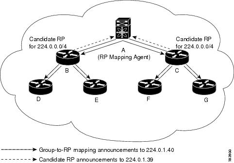
By default, routers are not enabled to listen or forward Auto-RP messages. You must enable the Auto-RP listening and forwarding feature so that the Auto-RP mechanism can dynamically inform routers in the PIM domain of the group-to-RP mapping.
Note |
Auto-RP is not supported for PIM6. |
For information about configuring Auto-RP, see Configuring Auto-RP.
Multiple RPs Configured in a PIM Domain
This section describes the election process rules when multiple RPs are configured in a PIM domain.
PIM BSR Bootstrap/Auto-RP Mapping-Agent Election Process
This section describes the BSR bootstrap Auto-RP mapping-agent election process.
Bootstrap Router (BSR) Election Process Details
-
If the BSR priorities are different, the BSR with the highest priority (highest numerical value) is elected as the BSR router for the PIM domain (see configuration example 1).
-
Configuration example 1—Different BSR-candidate priorities: In this example, the system elects the device labeled N7K-1 as the BSR candidate for the PIM domain because it has the highest priority. The device labeled N7K-2 has the default priority of 64.
-
|
Configuration for N7K-1: |
|
Configuration for N7K-2: |
|
Verification for N7K-1: |
|
Verification for N7K-2: |
-
If the BSR priorities are the same, the BSR with the highest BSR-candidate IP address is elected as the BSR router for the PIM domain (see configuration example 2).
-
Configuration example 2—Identical BSR-candidate priorities: In this example, the system elects the device labeled N7K-2 as the BSR for the PIM domain because it has the highest BSR-candidate IP address.
-
|
Configuration for N7K-1: |
|
Configuration for N7K-2: |
|
Verification for N7K-1: |
|
Verification for N7K-2: |
Auto-RP Mapping Agent Election Process
-
The router with the highest mapping-agent IP address is elected as the mapping agent for the PIM domain. You cannot configure the priority for the Auto-RP mapping agent (see configuration example):
-
Configuration example—Highest IP address: In this example, the system elects the device labeled N7K-2 as the mapping agent for the PIM domain because it has the highest mapping-agent IP address.
-
|
Configuration for N7K-1: |
|
Configuration for N7K-2: |
|
Verification for N7K-1: |
|
Verification for N7K-2: |
PIM RP versus RP Election Process
This table shows the process that the system uses to select the RP for a multicast group if multiple RPs are configured in the network using BSR, Auto-RP, or static RP configurations.
|
BSR-RP vs. BSR-RP |
BSR-RP vs. Static RP |
Auto-RP vs. Auto- RP |
Auto-RP vs. Static RP |
|---|---|---|---|
|
1. Most specific RP group-list |
1.Most specific RP group-list |
1. Most specific RP group-list |
1. Most specific RP group-list |
|
2. Lowest RP priority |
2. Highest RP IP address |
2. Highest RP IP address |
2. Highest RP IP address |
|
3. Highest RP IP address |
— |
— |
— |
Note |
BSR-RP versus Auto-RP is not listed in this table because we recommend that you do not run both simultaneously in the same network. |
PIM BSR RP-Candidate Versus BSR RP-Candidate Election Process
-
The BSR RP-candidate with the most specific group list is elected as the RP for any multicast addresses specified in its configured group list. The most specific group list takes priority over the BSR RP-candidate priority and the highest BSR RP-candidate IP address (see configuration example 1).
-
Configuration example 1—Most specific group list: In this example, the system elects the device labeled N7K-1 as the RP for all multicast addresses specified in the 224.1.1.0/24 group-list. The system elects the device labeled N7K-2 for the multicast addresses within the less specific 224.0.0.0/4 group list.
-
|
Configuration for N7K-1: |
|
Configuration for N7K-2: |
|
Verification for N7K-1: |
|
Verification for N7K-2: |
-
When multiple BSR RP-candidates advertise the same group list (for example, 224.0.0.0/4), the system elects the BSR RP-candidate with the highest priority (lowest numerical value) as the RP for any multicast address specified in its group list (see configuration example 2).
-
Configuration example 2—Identical group list with different RP priorities: In this example, the system elects the device labeled N7K-1 as the RP for all multicast addresses specified in the 224.0.0.0/4 group list because it has the lowest RP-candidate priority. The device labeled N7K-2 has a default priority of 192.
-
|
Configuration for N7K-1: |
|
Configuration for N7K-2: |
|
Verification for N7K-1: |
|
Verification for N7K-2: |
-
When multiple BSR RP-candidates advertise the same group list (for example, 224.0.0.0/4) and are configured with the same BSR RP-candidate priority, the system elects the BSR RP-candidate with the highest IP address as the RP for any multicast address specified in its group list (see configuration example 3).
-
Configuration example 3—Identical group list with identical RP priorities: In this example, the system elects the device labeled N7K-2 as the RP for all multicast addresses specified in the 224.0.0.0/4 group list because it has the highest RP-candidate IP address.
-
|
Configuration for N7K-1: |
|
Configuration for N7K-2: |
|
Verification for N7K-1: |
|
Verification for N7K-2: |
PIM BSR RP-Candidate Versus Static RP Election Process
-
The RP with the most specific group list is elected as the RP for any multicast addresses specified in its configured group list. The most specific group list takes priority over the highest RP IP address (see configuration example 1). (RP priorities are not applicable when comparing BSR RP-candidates to static RPs.)
-
Configuration example 1—Most specific group list: In this example, the system elects the device labeled N7K-1 as the BSR RP for all multicast addresses specified in the 224.1.1.0/24 group list. The system elects the device labeled N7K-2 as the RP for the multicast addresses within the less specific 224.0.0.0/4 group list because of the static RP statement.
-
|
Configuration for N7K-1: |
|
Configuration for N7K-2: |
|
Verification for N7K-1: |
|
Verification for N7K-2: |
-
When a static RP and the BSR RP-candidate advertise the same group list (for example, 224.0.0.0/4), the system elects the system with the highest RP IP address as the RP for any multicast addresses specified in its group list (see configuration example 2).
-
Configuration example 2—Identical RP group list: In this example, the system elects the device labeled N7K-2 as the RP for all multicast addresses specified in the 224.0.0.0/4 group list because it has the highest RP IP address.
-
|
Configuration for N7K-1: |
|
Configuration for N7K-2: |
|
Verification for N7K-1: |
|
Verification for N7K-2: |
-
Because you cannot configure a static RP and its default value is 0, the RP priority has no impact. You can configure the BSR RP-candidate with a value between 0 and 255. The system elects the device with the most specific group list. If both devices have the same group list, the system elects the device with the highest RP IP address (see configuration example 3).
-
Configuration example 3—Identical group list and identical RP priorities: In this example, the system elects the device labeled N7K-2 as the RP for all multicast addresses specified in the 224.0.0.0/4 group list because it has the highest RP IP address. The system does not compare RP priorities between BSR RPs and static RPs.
-
|
Configuration for N7K-1: |
|
Configuration for N7K-2: |
|
Verification for N7K-1: |
|
Verification for N7K-2: |
PIM Auto-RP-Candidate Versus Auto-RP-Candidate Election Process
The auto-RP-candidate election is similar to the BSR RP-candidate election process, but it does not support priorities (see the PIM BSR RP-Candidate vs. BSR RP-Candidate Election Process). You cannot configure the priority for an auto-RP. The default value is 0.
PIM Auto-RP-Candidate Versus Static RP Election Process
The auto-RP-candidate versus static RP election uses the same rules as the election process for the BSR RP-candidate versus static RP See PIM BSR RP-Candidate vs. Static RP Election Process.
Anycast-RP
Anycast-RP has two implementations: one uses Multicast Source Discovery Protocol (MSDP) and the other is based onRFC 4610, Anycast-RP Using Protocol Independent Multicast (PIM). This section describes how to configure PIM Anycast-RP.
You can use PIM Anycast-RP to assign a group of routers, called the Anycast-RP set, to a single RP address that is configured on multiple routers. The set of routers that you configure as Anycast-RPs is called the Anycast-RP set. This method is the only RP method that supports more than one RP per multicast group, which allows you to load balance across all RPs in the set. The Anycast RP supports all multicast groups.
PIM register messages are sent to the closest RP and PIM join-prune messages are sent in the direction of the closest RP as determined by the unicast routing protocols. If one of the RPs goes down, unicast routing ensures these message will be sent in the direction of the next-closest RP.
You must configue PIM on the loopback interface that is used for the PIM Anycast RP.
For more information about PIM Anycast-RP, see RFC 4610.
For information about configuring Anycast-RPs, see Configuring a PIM Anycast-RP Set.
PIM Register Messages
PIM register messages are unicast to the RP by designated routers (DRs) that are directly connected to multicast sources. The PIM register message has the following functions:
-
To notify the RP that a source is actively sending to a multicast group.
-
To deliver multicast packets sent by the source to the RP for delivery down the shared tree.
The DR continues to send PIM register messages to the RP until it receives a Register-Stop message from the RP. The RP sends a Register-Stop message in either of the following cases:
-
The RP has no receivers for the multicast group being transmitted.
-
The RP has joined the SPT to the source but has not started receiving traffic from the source.
You can use the ip pim register-source command to configure the IP source address of register messages when the IP source address of a register message is not a uniquely routed address to which the RP can send packets. This situation might occur if the source address is filtered so that the packets sent to it are not forwarded or if the source address is not unique to the network. In these cases, the replies sent from the RP to the source address will fail to reach the DR, resulting in Protocol Independent Multicast sparse mode (PIM-SM) protocol failures.
This example shows how to configure the IP source address of the register message to the loopback 3 interface of a DR:
ip pim register-source loopback 3
Note |
In Cisco NX-OS, PIM register messages are rate limited to avoid overwhelming the RP. |
You can filter PIM register messages by defining a routing policy. For information about configuring the PIM register message policy, see the Configuring Shared Trees Only for ASM.
Designated Routers
In PIM ASM and SSM modes, the software chooses a designated router (DR) from the routers on each network segment. The DR is responsible for forwarding multicast data for specified groups and sources on that segment.
The DR for each LAN segment is determined as described in the Hello Messages.
In ASM mode, the DR is responsible for unicasting PIM register packets to the RP. When a DR receives an IGMP membership report from a directly connected receiver, the shortest path is formed to the RP, which may or may not go through the DR. The result is a shared tree that connects all sources transmitting on the same multicast group to all receivers of that group.
In SSM mode, the DR triggers (*, G) or (S, G) PIM join messages toward the RP or the source. The path from the receiver to the source is determined hop by hop. The source must be known to the receiver or the DR.
For information about configuring the DR priority, see the Configuring PIM or PIM6 Sparse Mode.
Designated Forwarders
In PIM Bidir mode, the software chooses a designated forwarder (DF) at RP discovery time from the routers on each network segment. The DF is responsible for forwarding multicast data for specified groups on that segment. The DF is elected based on the best metric from the network segment to the RP.
If the router receives a packet on the RPF interface toward the RP, the router forwards the packet out all interfaces in the OIF-list. If a router receives a packet on an interface on which the router is the elected DF for that LAN segment, the packet is forwarded out all interfaces in the OIF-list except the interface that it was received on and also out the RPF interface toward the RP.
Note |
Cisco NX-OS does not support PIM Bidir mode on F2 modules. |
Note |
Cisco NX-OS puts the RPF interface into the OIF-list of the MRIB, but not in the OIF-list of the MFIB. |
ASM Switchover from Shared Tree to Source Tree
Note |
Cisco NX-OS puts the RPF interface into the OIF-list of the MRIB, but not in the OIF-list of the MFIB. |
In ASM mode, the DR that is connected to a receiver switches over from the shared tree to the shortest-path tree (SPT) to a source unless you configure the PIM parameter to use shared trees only. For information about configuring the use of shared trees only, see the Configuring Shared Trees Only for ASM.
During the switchover, messages on the SPT and shared tree may overlap. These messages are different. The shared tree messages are propagated upstream toward the RP, while SPT messages go toward the source.
For information about SPT switchovers, see the “Last-Hop Switchover” to the SPT section in RFC 4601.
ECMP Multicast Load Splitting Based on Source Group and Next-Hop Address Overview
The Advanced Multicast Multipath Support feature adds support for Equal Cost Multipath (ECMP) multicast load splitting based on source, group, and next-hop address. This feature enables multicast traffic from devices that send many streams to groups or that broadcast many channels, such as IPTV servers or MPEG video servers, to be more effectively load split across equal-cost paths.
Configuring ECMP multicast load splitting based on source, group, and next-hop address enables a more complex hash, the next-hop-based S-G-hash algorithm, which is based on source, group, and next-hop address. The next-hop-based S-G-hash algorithm is predictable because no randomization is used in calculating the hash value. Unlike the S-hash and basic S-G-hash algorithms, the hash mechanism used by the next-hop-based S-G-hash algorithm is not subject to polarization.
Note |
The next-hop-based S-G-hash algorithm in IPv4 multicast is the same algorithm used in IPv6 ECMP multicast load splitting, which, in turn, utilizes the same hash function used for PIM-SM bootstrap device (BSR). |
The next-hop-based hash mechanism does not produce polarization and also maintains better RPF stability when paths fail. These benefits come at the cost that the source or RP IP addresses cannot be used to reliably predict and engineer the outcome of load splitting when the next-hop-based S-G-hash algorithm is used. Because many customer networks have implemented equal-cost multipath topologies, the manual engineering of load splitting, thus, is not a requirement in many cases. Rather, it is more of a requirement that the default behavior of IP multicast be similar to IP unicast; that is, it is expected that IP multicast use multiple equal-cost paths on a best-effort basis. Load splitting for IPv4 multicast, therefore, could not be enabled by default because of the anomaly of polarization.
Note |
Load splitting for CEF unicast also uses a method that does not exhibit polarization and likewise cannot be used to predict the results of load splitting or engineer the outcome of load splitting. |
The next-hop-based hash function avoids polarization because it introduces the actual next-hop IP address of PIM neighbors into the calculation, so the hash results are different for each device, and in effect, there is no problem of polarization. In addition to avoiding polarization, this hash mechanism also increases stability of the RPF paths chosen in the face of path failures. Consider a device with four equal-cost paths and a large number of states that are load split across these paths. Suppose that one of these paths fails, leaving only three available paths. With the hash mechanism used by the polarizing hash mechanisms (the hash mechanism used by the S-hash and basic S-G-hash algorithms), the RPF paths of all states would likely reconverge and thus change between those three paths, especially those paths that were already using one of those three paths. These states, therefore, may unnecessarily change their RPF interface and next-hop neighbor. This problem exists simply because the chosen path is determined by taking the total number of paths available into consideration by the algorithm, so once a path changes, the RPF selection for all states is subject to change too. For the next-hop-based hash mechanism, only the states that were using the changed path for RPF would need to reconverge onto one of the three remaining paths. The states that were already using one of those paths would not change. If the fourth path came back up, the states that initially used it would immediately reconverge back to that path without affecting the other states.
Note |
The next-hop-based S-G-hash algorithm ignores bidir-PIM groups. |
Administratively Scoped IP Multicast
The administratively scoped IP multicast method allows you to set boundaries on the delivery of multicast data. For more information, see RFC 2365.
You can configure an interface as a PIM boundary so that PIM messages are not sent out that interface. For information about configuring the domain border parameter, see the Configuring PIM or PIM6 Sparse Mode.
You can use the Auto-RP scope parameter to set a time-to-live (TTL) value. For more information, see the Configuring Shared Trees Only for ASM.
Bidirectional Forwarding Detection for PIM
Beginning with Cisco NX-OS Release 5.0(2a), Bidirectional Forwarding Detection (BFD) allows the system to rapidly detect failures in a network. See the Cisco Nexus 7000 Series NX-OS Unicast Routing Configuration Guide, Release 6.x, for more information about BFD.
In PIM, a link or neighbor group failure is detected when the hold-time, which is set as part of the hello interval, expires. However, BFD provides a more efficient method to detect a failure. This protocol establishes a session between the two endpoints over a link and uses the forwarding engine. When BFD is enabled, the PIM process attempts to add a BFD session as each neighbor is discovered. If a BFD session already exists, no duplicate is created but PIM receives a callback that contains the state of the BFD session. You can enable BFD for PIM per VRF or per interface.
PIM removes the BFD session when you disable BFD for that VRF or interface, the interface is no longer a PIM interface, or the neighboring BFD session goes down.
Virtualization Support
A virtual device context (VDC) is a logical representation of a set of system resources. Within each VDC, multiple virtual routing and forwarding (VRF) instances can be defined. For each VRF in a VDC in the system, independent multicast system resources are maintained, including the MRIB and M6RIB.
You can use the PIM and PIM6 show commands with a VRF argument to provide a context for the information displayed. The default VRF is used if no VRF argument is supplied.
For information about configuring VDCs, see the Cisco Nexus 7000 Series NX-OS Virtual Device Context Configuration Guide.
For information about configuring VRFs, see the Cisco Nexus 7000 Series NX-OS Unicast Routing Configuration Guide.
Support for Graceful Restart PIM
The Support for Graceful Restart protocol independent multicast (PIM) feature is a multicast High Availability (HA) enhancement that improves the convergence of multicast-routes (mroutes) after a Route Processor (RP) switchover. In the event of an RP switchover, the support for Graceful Restart PIM feature utilizes the Generation ID (GenID) value (defined in RFC 4601) as a mechanism to trigger adjacent PIM neighbors on an interface to send PIM join messages for all (*, G) and (S, G) states that use that interface as a reverse path forwarding (RPF) interface. This mechanism enables PIM neighbors to immediately reestablish those states on the newly active RP.
Prerequisites for Graceful Restart PIM
All Protocol Independent Multicast (PIM) neighbors must be compliant with RFC 4601 and be able to process Generation ID (GenID) differences in PIM hello messages.
Information About Graceful Restart PIM
Generation IDs
A Generation ID (GenID) is a randomly generated 32-bit value that is regenerated each time protocol independent multicast (PIM) forwarding is started or restarted on an interface. In order to process the GenID value in PIM hello messages, PIM neighbors must be running Cisco software with an implementation of PIM that is compliant with RFC 4601.
Note |
PIM neighbors that are not compliant with RFC 4601 and are unable to process GenID differences in PIM hello messages will ignore the GenIDs. |
Graceful Restart PIM Functional Overview
The figure illustrates the operations that occur after a Route Processor (RP) switchover on devices that support the support for Graceful Restart protocol independent multicast (PIM) feature.
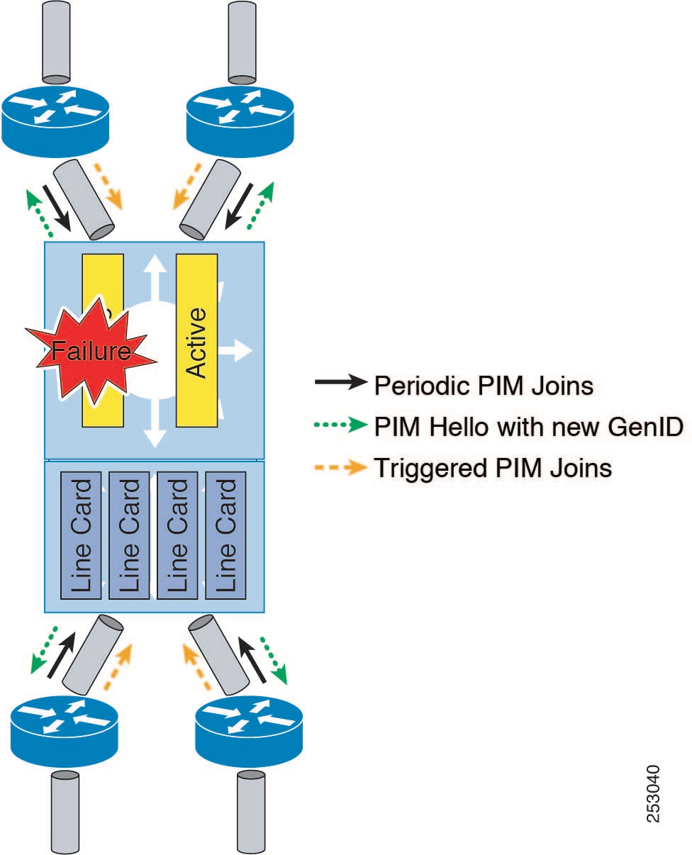
The mechanics of the support for Graceful Restart PIM feature are as follows:
-
In steady state, PIM neighbors exchange periodic PIM hello messages.
-
An active RP receives PIM joins periodically to refresh multicast-route (mroute) states.
-
When an active RP fails, the standby RP takes over to become the new active RP.
-
The new active RP then modifies the Generation ID (GenID) value and sends the new GenID in PIM hello messages to adjacent PIM neighbors.
-
Adjacent PIM neighbors that receive PIM hello messages on an interface with a new GenID send graceful restart PIM for all (*, G) and (S, G) mroutes that use that interfaces as an RPF interface.
-
Those mroute states are then immediately reestablished on the newly active RP.
Graceful Restart PIM and Multicast Traffic Flow
Multicast traffic flow on PIM neighbors is not affected if the multicast traffic detects support for Graceful Restart PIM or PIM hello message from a node with the failing RP within the default PIM hello hold-time interval. Multicast traffic flow on a failing RP is not affected if it is Non-Stop Forwarding (NSF) capable.
Caution |
The default PIM hello hold-time interval is 3.5 times the PIM hello period. Multicast High Availability (HA) operations may not function as per design if you configure PIM hello interval with a value lower than the default value of 30 seconds. |
Additional References for Graceful Restart PIM
RFCs
| RFC | Title |
|---|---|
|
Protocol Independent Multicast - Sparse Mode (PIM-SM) |
Technical Assistance
| Description | Link |
|---|---|
|
The Cisco Support website provides extensive online resources, including documentation and tools for troubleshooting and resolving technical issues with Cisco products and technologies. To receive security and technical information about your products, you can subscribe to various services, such as the Product Alert Tool (accessed from Field Notices), the Cisco Technical Services Newsletter, and Really Simple Syndication (RSS) Feeds. Access to most tools on the Cisco Support website requires a Cisco.com user ID and password. |
High Availability
For information about high availability, see the Cisco Nexus 7000 Series NX-OS High Availability and Redundancy Guide.

 Feedback