Overview of LISP Instance ID
The LISP Instance ID provides a means of maintaining unique address spaces (or "address space segmentation") in the control and data plane. Instance IDs are numerical tags defined in the LISP canonical address format (LCAF). The Instance ID has been added to LISP to support virtualization.
When multiple organizations inside of a LISP site are using private addresses as Endpoint ID (EID) prefixes, their address spaces must remain segregated due to possible address duplication. An Instance ID in the address encoding can be used to create multiple segmented VPNs inside of a LISP site where you want to keep using EID-prefix-based subnets. The LISP Instance ID is currently supported in LISP ingress tunnel routers and egress tunnel routers (ITRs and ETRs, collectively known as xTRs), map server (MS) and map resolver (MR).
This chapter explains how to configure LISP xTRs with LISP MS and MR to implement virtualization. The content considers different site topologies and includes guidance to both shared and parallel LISP model configurations. It includes conceptual background and practical guidance, and provides multiple configuration examples.
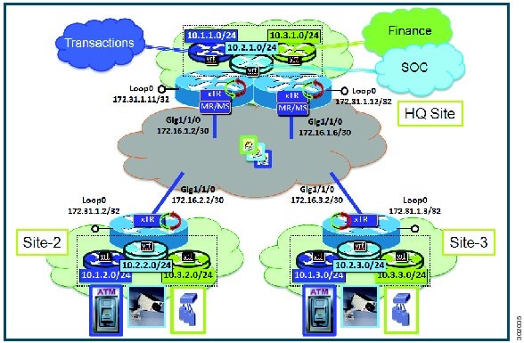
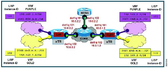
The purpose of network virtualization, as illustrated the following figure, is to create multiple, logically separated topologies across one common physical infrastructure.
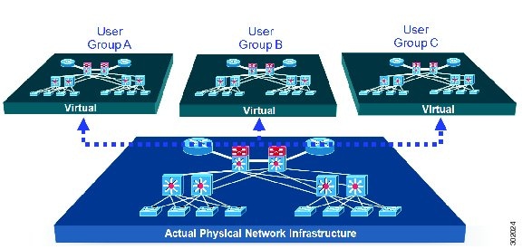
When you plan the deployment of a LISP virtualized network environment, you must plan for virtualization at both the device level and the path level.
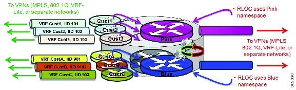
For path level virtualization: LISP binds virtual routing and forwarding (VRFs) to instance IDs (IIDs). These IIDs are included in the LISP header to provide data plane (traffic flow) separation.
For device level virtualization: Both the EID and the RLOC namespaces can be virtualized. The EID can be virtualized by binding a LISP instance ID to an EID VRF; the RLOC by tying locator addresses and associated mapping services to the specific VRF within which they are reachable.
Prerequisites for LISP Instance-ID Support
-
Allow the use of instance-id 0's within a virtual routing and forwarding (VRF) instance.
Guidelines and Limitations for LISP Instance-ID Support
The LISP Instance-ID Support feature has the following configuration guidelines and restrictions:
-
If you enable LISP, nondisruptive upgrade (ISSU) and nondisruptive downgrade (ISSD) paths are not supported. Disable LISP prior to any upgrade. This restriction applies only to releases before 6.2(2), not to 6.2(2) or subsequent LISP releases.
Device Level Virtualization
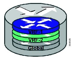
Virtualization at the device level uses virtual routing and forwarding (VRF) to create multiple instances of Layer 3 routing tables, as shown in the figure below. VRFs provide segmentation across IP addresses, allowing for overlapped address space and traffic separation. Separate routing, quality of service (QoS), security, and management policies can be applied to each VRF instance. An interior gateway protocol (IGP) or exterior gateway protocol (EGP) routing process is typically enabled within a VRF, just as it would be in the global (default) routing table. LISP binds VRFs to instance IDs for similar purposes.
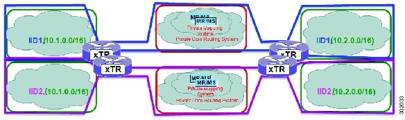
Path Level Virtualization
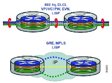
VRF table separation is maintained across network paths, as shown in the following figure. Single-hop path segmentation (hop by hop) is typically accomplished by using 802.1q VLANs, virtual path identifier/virtual circuit identifier password (VPI/VCI PW), or easy virtual network (EVN). You can also use the Locator ID Separation Protocol (LISP) in multihop mechanisms that include Multiprotocol Label Switching (MPLS) and generic routing encapsulation (GRE) tunnels. LISP binds VRF instances to instance IDs (IIDs), and then these IIDs are included in the LISP header to provide data plane (traffic flow) separation for single or multihop needs.
LISP Virtualization at the Device Level
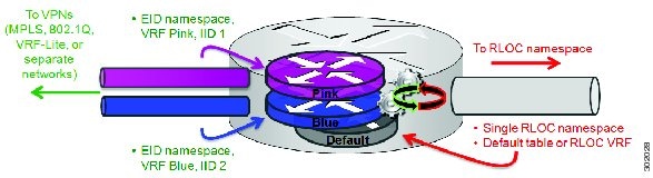
LISP implements Locator ID separation and thereby creates two namespaces; endpoint ID (EID) and routing locator (RLOC). Either or both of these can be virtualized.
-
EID virtualization—Enabled by binding a LISP instance ID to an EID virtual routing and forwarding (VRF). Instance IDs are numerical tags defined in the LISP canonical address format (LCAF) draft, and are used to maintain address space segmentation in both the control plane and data plane.
-
Routing locator (RLOC) virtualization—Tying locator addresses and associated mapping services to the specific VRF within which they are reachable enables RLOC virtualization.
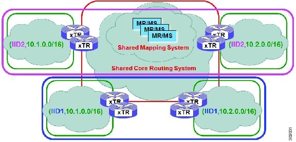
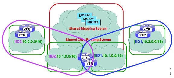
Because LISP can virtualize either or both of these namespaces, two models of operation are defined: the shared model and the parallel model. To understand how these models differ from the non-virtualized model of LISP, review information about the default (non-virtualized) model of LISP before reading about the shared model and the parallel model.
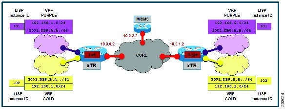
Default (Non-Virtualized) LISP Model
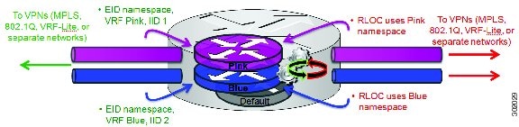
By default, LISP is not virtualized in the EID space or the RLOC space. That is, unless otherwise configured, both EID and RLOC addresses are resolved in the default (global) routing table. See the following figure.
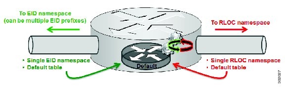
The mapping system must also be reachable through the default table. This default model can be thought of as a single instantiation of the parallel model of LISP virtualization where EID and RLOC addresses are within the same namespace.

 Feedback