Configuring Dynamic FCoE Using FabricPath

This chapter contains the following sections:

Information About Dynamic FCoE Using FabricPath

Fibre Channel over Ethernet (FCoE) enables I/O consolidation. It permits both LAN and SAN traffic to coexist on the same switch and the same wire. This feature enables you to consolidate multiple separate networks into a single converged infrastructure.

Key values of I/O consolidation using traditional FCoE are as follows:

  • Elimination of separate network infrastructures for SAN and LAN traffic.

  • Reduction in hardware requirements, such as cabling and server interface cards (NICs and HBAs), and lowering capital expense.

  • Reduction in power and cooling requirements for fewer physical assets.

  • Increasing deployment agility for multiprotocol networks, which preserves long-term investments while preparing for future uncertainty in protocol needs.

By using FabricPath Ethernet technology, you can take FCoE consolidation even further:

  • Create a logical, rather than physical, SAN A/B separation.

  • Efficiently load balance multiprotocol traffic within the data center.

  • Dynamically establish relationships between switches, reducing the possibility for human error during configurations.

  • Improved high availability percentages as the scale increases.

The FabricPath architecture provides an inherent multipath capability with redundancy to handle node failures. Fabric level redundancy is provided through a double fabric model (SAN A/SAN B). The separation of the two SANs is logically implemented as two different VSANs that map to two different VLANs (VLAN A and B). Fibre channel traffic in SAN A becomes the FCoE traffic in VLAN A, the Fiber Channel traffic in SAN B becomes the FCoE traffic in VLAN B, and the LAN traffic is carried on one or more additional VLANs over the converged Ethernet infrastructure. In this logical environment, the VSAN A/VSAN B configuration protects against fabric-wide control plane failures.

The traditional method of hosts that connect to two separate SANs is still supported with the FCoE over FabricPath architecture. The host is connected to two different leaf nodes that host a disjointed set of VSANs. Beyond these leaf nodes, the fabric is converged on the same infrastructure, but the host continues to see two SAN fabrics.

The following figure shows a FabricPath topology with n spines (S) and m leafs (L). The m leafs communicate to each other through the n spines using FabricPath encapsulation.
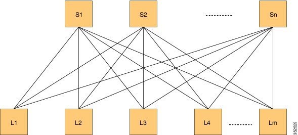
Figure 1. FabricPath Topology

DFA Topology

FCoE creates an overlay of FCoE virtual links on top of the underlying Ethernet topology, irrespective of how that Ethernet topology is constructed and which protocol is used to compute the MAC address routes.

In a dynamic FCoE environment, the topology is developed using the leafs as FCoE Forwarder (FCF) switches that are forwarded through transparent spines.

FCoE hosts and FCoE storage devices are connected to a FabricPath topology through the leaf switches. In this configuration, only the leaf switches perform FCoE forwarding (only the leaf switches behave as FCFs); the spine switches just forward MAC-in-MAC encapsulated Ethernet frames that are based on the outer destination MAC address.

The following figure shows the logical FCoE overlay topology of VE_Port to VE_Port virtual links on a FabricPath topology.
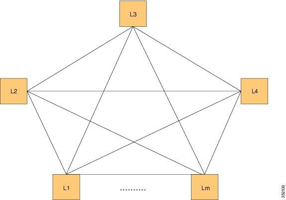
Figure 2. FCoE Overlay of VE_Port to VE_Port Virtual Links

FCoE Overlay of VE_Port to VE_Port Virtual Links

Only the FCFs, that are implemented by the leaf switches are part of this overlay topology. This topology is seen by Fabric Shortest Path First (FSPF), for each FCoE VLAN. FSPF computes over which virtual link to forward an FCoE frame based on its DomainID (D_ID). A virtual link is uniquely identified by the pair of MAC addresses associated with the two VE_Ports logically connected by it. Identifying the virtual link is equivalent to identifying which MAC addresses to use for the FCoE encapsulation on the transport network.

Use Lm as the number of leafs that are feature enabled. The feature might not be enabled on all leafs. The FCoE mesh is basically the leafs where FCoE or FabricPath is enabled.

SAN A/B Separation
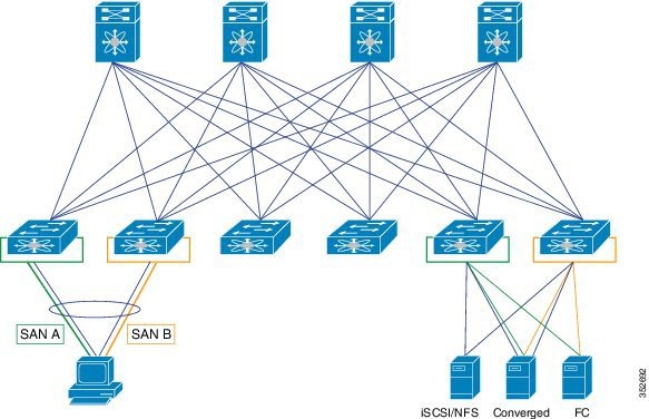
For Dynamic FCoE, SAN A/B separation is realized in a logical manner across the backbone. As shown in the following illustration, physical SAN A/B separation is maintained from the FCF leafs to the end devices. Beyond the leafs, FCoE traffic for SANs A and B are carried by FabricPath Equal Cost Multipathing (ECMP) links across all spines, maintaining logical SAN A/B separation.
Figure 3. Physical Topology Diagram


In the previous figure, the physical connectivity for the topology follows typical leaf/spine CLOS architectural best practices. Logically, SAN A and SAN B are isolated at the Top of Rack (ToR) switches physically. Once the traffic enters the FabricPath network, the storage traffic is logically separated (see the following figure) across the network where it is physically separated once more to the storage device edge.
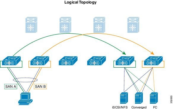
Figure 4. Logical Topology Diagram


Dynamic FCoE gains the additional redundancy that is inherent in the FabricPath network by using the increased spine connectivity. A larger network with a large number of spines means increased reliability and stability for the storage network. This is achieved while retaining the best practices requirements for storage environments.

Load-Balancing FCoE Traffic on a Dynamic VFC

FabricPath provides redundant paths between a source and destination. Because FCoE traffic traverses the FabricPath network with one or more FCoE and non-FCoE nodes (spines, leafs), you must ensure in-order delivery through proper port-channel hashing across the redundant paths. All FabricPath nodes have port-channel hashing enabled that includes the exchange ID. Traffic from a single flow always traverses through only one set of nodes through the network to maintain in-order delivery.

Supported Dynamic FCoE Using FabricPath Topologies

The supported topologies for Dynamic FCoE Using FabricPath are as follows:

  • FCoE devices that are directly connected to an FCF leaf

  • Traditional FCoE VE_Port connectivity to an FCF leaf

  • Legacy FC fabric connected to an FCF leaf

  • NPV and FCoE NPV devices that are connected to an FCF leaf

  • Native FC devices that are directly connected to an FCF leaf


Note


Although physical separation is possible through a multi-topology configuration of FabricPath, it is not required.


Prerequisites for Dynamic FCoE Using FabricPath

Dynamic FCoE prerequisites are as follows:

  • You must enable FabricPath.

  • You must enable feature fcoe for the FCF leafs.

  • You must assign the highest FabricPath cost to the MCT if there is a vPC+ MCT on the FCF leafs.

  • You must enable mode fabric path on the VLANs that are mapped to VSANs in all the nodes ( leafs and spines).

Guidelines and Limitations for Dynamic FCoE Using FabricPath

Dynamic FCoE Using FabricPath has the following guidelines and limitations:

  • You must enable feature FCoE on the FabricPath leaf node.

  • You must enable mode FabricPath on FCoE VLANs used for storage traffic.

  • The minimum number of switches for a FabricPath deployment is one switch. However, if you are going to have a separation of SAN A/B, you need to have two spine switches. Otherwise, there is no separation at all.

  • You must statically define the FabricPath switch ID. Changing a switch ID is required for a dynamic vFC. Some traffic loss might occur during a switch ID change. We recommend that you statically configure switch IDs.

  • A multichassis EtherChannel trunk (MCT) must be of the highest Intermediate System-to-Intermediate System (IS-IS) cost which is 16777215. FCoE VLANs do not come up as an MCT. Fabric IS-IS should be high so that FCoE/FTP traffic does not go through.

  • You should ensure the following:

    • Define the FCoE VLAN in a separate topology and explicitly prune the MCT links.

    • Configure a higher cost on MCT to avoid using it for regular forwarding.

  • Shutting a VFC dynamically is not recommended because a Layer 2 Multipathing (L2MP) loop might occur and result in traffic loss.

  • If you want to take a certain data path for a VSAN, use a FabricPath multitopology in the Dynamic FCoE Using FabricPath topology.

Configuration Topology Example

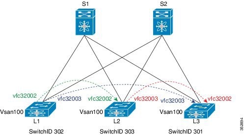
The following figure represents the configuration example that will be described in the following sections.

Figure 5. Configuration Example

Configuration Example


Note


The component labels in the previous diagram are for illustrative purposes only.

Configuring Dynamic FCoE Using FabricPath

SUMMARY STEPS

  1. Establish the FabricPath infrastructure.
  2. Configure non-FCoE leafs for FCoE traffic.
  3. Configure leafs for FCoE (FCF) processing.
  4. Configure ports on leafs for FC/FCoE.

DETAILED STEPS


Step 1

Establish the FabricPath infrastructure.

Step 2

Configure non-FCoE leafs for FCoE traffic.

Step 3

Configure leafs for FCoE (FCF) processing.

A leaf needs this configuration for failover cases.

Step 4

Configure ports on leafs for FC/FCoE.


Instantiation and Initialization of Dynamic VFC

Dynamic FCoE enables the capability of creating both a virtual Fibre Channel port (VFC), as well as instantiating the Inter-Switch Link port type (VE_Port/TE Port). Enabling FCoE and FabricPath on the same VLAN should serve as a trigger to instantiation and initialization of the Dynamic VFCs in TE mode. The process is as follows:

  1. Every FCF leaf is uniquely identified by a global FCF-MAC address.

  2. Every FCF leaf floods an FIP unsolicited multicast discovery advertisement to ALL-FCF MAC addresses and source MAC addresses that are set to its global FCF-MAC address on the FabricPath-enabled FCoE VLANs. This is triggered by two factors:

    1. Feature FCoE is enabled on the leaf.

    2. FabricPath is enabled on the FCoE VLANs.

  3. All FCF leafs on this FabricPath cloud should receive this multicast advertisement on the corresponding FCoE-enabled FP VLAN. Upon receiving this FIP multicast frame, a dynamic VFC in VE mode is created between the two FCF leaf nodes.

  4. Only one dynamic VFC in TE mode is between any two FCF leafs.

  5. The dynamic VFCs can be differentiated based on their VFC ID range. All dynamic VFCs obtain an ID that is greater than 32001.

  6. The VFC might have multiple FabricPath FCoE VLANs up. The VLANs might or might not be in the same topology.

  7. Every FCF leaf is one hop away. For all VE paths that use FabricPath, a default fixed FSPF cost value is used.

Verifying the Dynamic FCoE Using FabricPath Configuration

Command Purpose

show interface brief

Displays a brief summary of the interface configuration information.

show interface vfc

Displays the configuration information of virtual Fibre Channel interfaces.

show vpc

Displays the configuration information of virtual port channels.

show topology

Displays topology information for connected SAN switches.

show fcoe

Displays the status of FCoE parameters on the switch.

show running-config

Displays the configuration that is currently running on the switch.

show fcoe dce

Displays the Dynamic FCoE database using FabricPath.

show interface brief Command

switch# show interface brief
--------------------------------------------------------------------------------
Ethernet      VLAN    Type Mode   Status  Reason                   Speed     Por
t
Interface                                                                    Ch 
#
--------------------------------------------------------------------------------
Eth1/1        1       eth  access up      none                        10G(D) --
Eth1/2        1       eth  access down    Link not connected          10G(D) --
Eth1/3        1       eth  access up      none                        10G(D) --
Eth1/4        1       eth  access up      none                        10G(D) --
Eth1/5        1       eth  access up      none                        10G(D) --
Eth1/6        1       eth  access up      none                        10G(D) --
Eth1/7        1       eth  access up      none                        10G(D) --
Eth1/8        1       eth  access down    SFP not inserted            10G(D) --
Eth1/9        1       eth  access down    SFP validation failed       10G(D) --
Eth1/10       1       eth  access down    SFP not inserted            10G(D) --
Eth1/11       1       eth  f-path up      none                        10G(D) --
Eth1/12       1       eth  access down    SFP not inserted            10G(D) --
Eth1/13       1       eth  access up      none                        10G(D) --
Eth1/14       1       eth  access up      none                        10G(D) --
Eth1/15       1       eth  access down    SFP validation failed       10G(D) --
Eth1/16       1       eth  access down    Link not connected          10G(D) --
Eth1/17       1       eth  access up      none                        10G(D) --
Eth1/18       1       eth  access up      none                        10G(D) --
Eth1/19       1       eth  access down    SFP validation failed       10G(D) --
Eth1/20       1       eth  access up      none                        10G(D) --
Eth1/21       1       eth  access down    SFP validation failed       10G(D) --
Eth1/22       1       eth  access up      none                        10G(D) --
Eth1/23       1       eth  access down    SFP validation failed       10G(D) --
Eth1/24       1       eth  access down    SFP not inserted            10G(D) --
Eth1/25       1       eth  access up      none                        10G(D) --
Eth1/26       1       eth  access up      none                        10G(D) --
Eth1/27       1       eth  access up      none                        10G(D) --
Eth1/28       1       eth  access up      none                        10G(D) --
Eth1/29       1       eth  access up      none                        10G(D) --
Eth1/30       1       eth  access down    SFP not inserted            10G(D) --
Eth1/31       1       eth  access down    SFP not inserted            10G(D) --
Eth1/32       1       eth  access down    SFP not inserted            10G(D) --

--------------------------------------------------------------------------------
Port   VRF          Status IP Address                              Speed    MTU
--------------------------------------------------------------------------------
mgmt0  --           up     10.193.52.117                           1000     1500

-------------------------------------------------------------------------------
Interface  Vsan   Admin  Admin   Status      Bind                 Oper    Oper
                  Mode   Trunk               Info                 Mode    Speed
                         Mode                                            (Gbps)
-------------------------------------------------------------------------------
vfc32002   1      E     on     trunking    54:7f:ee:b1:8a:00        TE   10
vfc32003   1      E     on     trunking    54:7f:ee:73:e8:00        TE   10
 		

show interface vfc Command

switch# show interface vfc 32002
vfc32002 is trunking
    Dynamic VFC Peer MAC is 54:7f:ee:b1:8a:00
    Hardware is Ethernet 
    Port WWN is 2d:01:54:7f:ee:73:e6:78
    Admin port mode is E, trunk mode is on
    snmp link state traps are enabled
    Port mode is TE
    Port vsan is 1
    Trunk vsans (admin allowed and active) (1,100)
    Trunk vsans (up)                       (100)
    Trunk vsans (isolated)                 ()
    Trunk vsans (initializing)             (1)
    1 minute input rate 0 bits/sec, 0 bytes/sec, 0 frames/sec
    1 minute output rate 0 bits/sec, 0 bytes/sec, 0 frames/sec
      0 frames input, 0 bytes
      0 frames output, 0 bytes
    Interface last changed at Mon Feb 14 19:46:53 2011

switch# show interface vfc 32003
vfc32003 is trunking
    Dynamic VFC Peer MAC is 54:7f:ee:73:e8:00
    Hardware is Ethernet 
    Port WWN is 2d:02:54:7f:ee:73:e6:78
    Admin port mode is E, trunk mode is on
    snmp link state traps are enabled
    Port mode is TE
    Port vsan is 1
    Trunk vsans (admin allowed and active) (1,100)
    Trunk vsans (up)                       (100)
    Trunk vsans (isolated)                 ()
    Trunk vsans (initializing)             (1)
    1 minute input rate 0 bits/sec, 0 bytes/sec, 0 frames/sec
    1 minute output rate 0 bits/sec, 0 bytes/sec, 0 frames/sec
      0 frames input, 0 bytes
      0 frames output, 0 bytes
    Interface last changed at Mon Feb 14 19:49:23 2011


===========================================================================

show vpc Command

switch# show vpc
			vPC domain id : 300 vPC+ switch id : 1550
   vPC Peer-link status
   ---------------------------------------------------------------------
   id   Port   Status Active vlans
   --   ----   ------ --------------------------------------------------
   1   Po1    up     -

show topology Command

switch# show topology
FC Topology for VSAN 100 :
--------------------------------------------------------------------------------
       Interface  Peer Domain Peer Interface     Peer IP Address(Switch Name)
--------------------------------------------------------------------------------
         vfc32002  0x0b(11)         vfc32002  10.193.52.108(nc-9)
         vfc32003 0x64(100)         vfc32003  10.193.52.118(o2-356)

show fcoe Command

switch# show fcoe
Global FCF details
        FCF-MAC is 54:7f:ee:73:e6:20
        FC-MAP is 0e:fc:00
        FCF Priority is 128
        FKA Advertisement period for FCF is 8 seconds

VFC MAC details

show fcoe dce Command

switch# show fcoe dce

Dynamic VFC MAC details :
-----------------------------------------------------------
   Interface    Peer-swid       Peer-mac 
-----------------------------------------------------------
   vfc32002     303             54:7f:ee:b1:8a:00       
   vfc32003     301             54:7f:ee:73:e8:00     

Configuration Output Examples for Dynamic FCoE Using FabricPath

The following output examples show how to configure Dynamic FCoE using FabricPath. You must enter the feature fabricpath command and configure the appropriate links as FabricPath core ports.

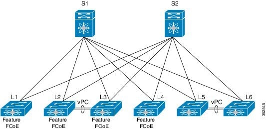
This example covers VSAN 100 and VSAN 200.

The following is a description of the topology example:

  • S1 and S2 are FabricPath spines.

  • L1 through L4 are FCF leafs.

  • L5 and L6 are non-FCoE leafs.

Figure 6. Sample Dynamic FCoE Configuration