- vPC and First Hop Redundancy Protocol
- ARP Processing with vPC
- Layer 3 Forwarding for Packets to a Peer Switch MAC Address
- Improved Convergence with a vPC Topology and Layer 3 Routing
- vPC Peer Link Failure
- Layer 3 Module Failure
- Connecting to a Router in a vPC Topology
- Dedicated VRF For a Keepalive Interface
- vPC Consistency Check for Layer 3 Parameters
- Multicast Interaction in a vPC Topology
- Faster Convergence with the Prebuilt Source Tree
- Using a vPC Switch as a Designated Router (PIM DR)
- Software Upgrade and Downgrade Impact
Cisco Nexus 5500 Platform Layer 3 and vPC Operations
This chapter describes virtual port channel (vPC) operations when Layer 3 routing features are enabled on the Cisco Nexus 5500 Platform.
This chapter includes the following sections:
- vPC and First Hop Redundancy Protocol
- ARP Processing with vPC
- Layer 3 Forwarding for Packets to a Peer Switch MAC Address
- Improved Convergence with a vPC Topology and Layer 3 Routing
- vPC Peer Link Failure
- Layer 3 Module Failure
- Connecting to a Router in a vPC Topology
- Dedicated VRF For a Keepalive Interface
- vPC Consistency Check for Layer 3 Parameters
- Multicast Interaction in a vPC Topology
- Faster Convergence with the Prebuilt Source Tree
- Using a vPC Switch as a Designated Router (PIM DR)
- Software Upgrade and Downgrade Impact
vPC and First Hop Redundancy Protocol
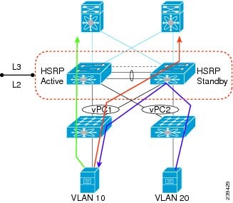
When you use a Cisco Nexus 5548 switch or Cisco Nexus 5596UP switch as a default gateway for hosts, you can deploy the First Hop Redundancy Protocol (FHRP) to provide default gateway redundancy. Beginning with Cisco NX-OS Release 5.0(3)N1(1b), an active FHRP peer and a standby peer can perform Layer 3 forwarding when you enable vPC. This optimization improves bandwidth, avoids sending the Layer 3 traffic over the vPC peer link, and requires no configuration or protocol change. Only the FHRP active peer answers ARP requests. Because both active and standby FHRP peers can forward Layer 3 traffic, you do not need to configure an aggressive timer for FHRP to provide faster failover and convergence time if an active FHRP peer fails.
Figure 2-1 shows that the Layer 3 traffic that originated from the host and is destined to a host several hops away can be routed by both the Host Standby Router Protocol (HSRP) active and the HSRP standby switch..
ARP Processing with vPC
When the host connects to a Cisco Nexus 5500 Platform switch and Cisco Nexus 2000 Fabric Extenders in a vPC topology, the host can send an ARP request to the FHRP standby peer due to a hashing algorithm. The ARP request that is received by the standby peer is forwarded to the active peer and the active peer can answer it with an ARP reply.
Similarly, when traffic is moving from north to south, such as when one Cisco Nexus 5500 Platform switch sends an ARP request to a host, the ARP reply might be sent to another switch. In such a case, the ARP reply is forwarded as a Layer 2 frame to the Cisco Nexus 5500 Platform switch that originated the ARP request.
As of Cisco NX-OS Release 5.0(3)N1(1b), ARP synchronization does not occur between two Cisco Nexus 5500 Platform switches. The two switches resolve and maintain their ARP table independently. When one vPC peer switch is reloaded, the switch needs to resolve the ARP by sending ARP requests to the hosts.
Layer 3 Forwarding for Packets to a Peer Switch MAC Address
Typically, a router performs a Layer 3 route table lookup and Layer 3 forwarding when the destination MAC in the Ethernet frame matches its own MAC address. Otherwise, the packets are switched (if Layer 2 functionality is enabled) or dropped. In a topology with Layer 3 and vPC enabled, a vPC peer switch could receive IP packets with the peer’s MAC address as the destination MAC rather than the virtual MAC address (when FHRP is enabled) or its own MAC address. In this scenario, a Cisco Nexus 5500 Platform switch can forward the traffic to the peer using a peer link and the peer switch performs the Layer 3 forwarding.
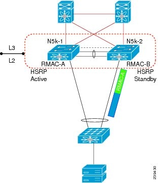
The above scenario often happens with some filers or with Layer 3 peering over vPC. In the case of filers, they may achieves improved load balance and better performance by forwarding traffic to the Burnt-in-Address (BIA) of the routers instead of the HSRP MAC.
Figure 2-2 shows that when the NAS filer sends out packets with N5k-1’s MAC RMAC-A as the destination MAC, the packets can be sent over to the N5k-2 switch due to the port channel hashing.
Figure 2-2 vPC and Peer-Gateway
Another scenario that could lead to this situation is when a router is connected to a Cisco Nexus 5500 Platform in a vPC topology.
Figure 2-3 Connecting to a Router in a vPC Topology
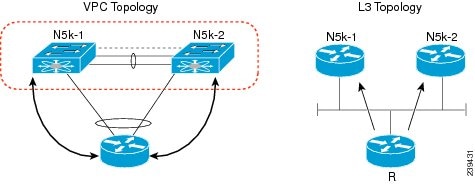
In Figure 2-3, router R considers N5k-1 and N5k-2 as two Layer 3 ECMP next-hop routers and runs ECMP hashing to choose which router to use as the actual next hop for a given flow. Router R connects to N5k-1 and N5k-2 via a vPC. This port channel has an IP address on router R, and Router R performs Layer 3 peering with N5k-1 and N5k-2 over this port channel. It runs the port channel hash algorithm to choose one physical link to reach the Layer 3 next hop. Because the Layer 3 ECMP and port channel run independent hash calculations there is a possibility that when the Layer 3 ECMP chooses N5k-1 as the Layer 3 next hop for a destination address while the port channel hashing chooses the physical link toward N5k-2. In this scenario,N5k-2 receives packets from R with the N5k-1 MAC as the destination MAC.
Sending traffic over the peer-link to the correct gateway is acceptable for data forwarding, but it is suboptimal because it makes traffic cross the peer link when the traffic could be routed directly.
Beginning in Cisco NX-OS Release 5.0(3)N1(1b), you can use the peer-gateway command to allow Cisco Nexus 5500 Platform switches to perform Layer 3 forwarding if the destination MAC of the incoming packet is the MAC of its vPC peer switch. The peer-gateway command avoids forwarding such packets to the vPC peer link.

Note![]() You must configure the peer-gateway command on both vPC peer switches.
You must configure the peer-gateway command on both vPC peer switches.
Improved Convergence with a vPC Topology and Layer 3 Routing
Beginning in Cisco NX-OS Release 5.0(3)N1(1b), a delay timer was introduced to avoid the situation where a vPC member port is brought up before the Layer 3 is converged. For example, when one Cisco Nexus 5500 Platform switch is reloaded, the switch starts to receive traffic from hosts once the vPC member ports are up. A delay might occur before the switch establishes a routing protocol adjacency and learns all routes. During this period of the time, received traffic is dropped due to the lack of a route-to-destination address. Figure 2-4 shows an example of where the delay can be used to avoid black hole traffic when a Cisco Nexus 5000 Platform switch is configured for Layer 3 with vPC.
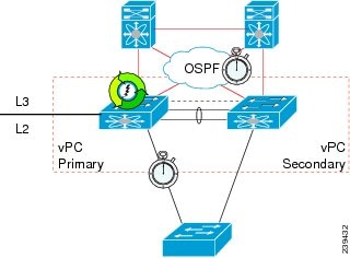
The delay restore feature allows you to configure a timed delay before vPC member ports are brought online. The delay allows the switch to learn all routes, to bring up the vPC member ports, and to forward traffic from hosts. The following example shows how to configure a timed delay of 120 seconds:
vPC Peer Link Failure
In addition to suspending vPC member ports, the vPC secondary switch also suspends its switched virtual interface (SVIs) when a vPC peer link is lost. When this occurs, the vPC secondary switch stops advertising the local subnets, which prevents traffic blackholing.
Layer 3 Module Failure
When a Layer 3 module fails on a Cisco Nexus 5500 Platform switch all Layer 3 interfaces are suspended, including Layer 3 port channel and SVI interfaces. As a result, the Layer 3 routing table on the neighboring routers is updated which results in the north to south traffic to be directed towards the peer Nexus 5500 Platform switch. The Layer 2 interfaces, including the Layer 2 port channel and out-of-band management interfaces, remain up.
In a non-vPC topology, when the Layer 3 and SVI interfaces are down, the redundant Cisco Nexus 5500 Platform switch becomes the active peer for all FHRP groups and it continues to forward traffic.
In a vPC topology, although the SVI interfaces are suspended, the vPC member ports are still up on the Cisco Nexus 5500 Platform switch. Even if the switch has a faulty Layer 3 module, Layer 2 traffic forwarding continues.
Figure 2-5 shows a topology where the Layer 3 module on N5k-2 fails. In this scenario, the Layer 3 connection toward the Layer 3 network and all SVI interfaces are suspended. However, the traffic from the hosts can still be sent to N5k-2 depending on the hash results. With the failure of the Layer 3 module, N5k-2 functions as a Layer 2 switch. It forwards the traffic to N5k-1, which forwards the traffic to the Layer 3 network. The return traffic is sent to N5k-1, which sends the traffic directly to the hosts.
Figure 2-5 Layer 3 Module Failure
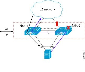
Note![]() Only the Layer 3 traffic needs to cross the peer link. The VLAN traffic is switched by N5k-2 locally.
Only the Layer 3 traffic needs to cross the peer link. The VLAN traffic is switched by N5k-2 locally.
The peer gateway is disabled on both vPC switches if the Layer 3 module fails on one switch.
For topologies with in-band management, the failure of a Layer 3 module means that the connectivity to the management network and the management system is also lost.
Connecting to a Router in a vPC Topology
When you connect a router to a pair of Cisco Nexus 5500 Platform switches in a vPC topology and enable routing, traffic forwarding may result in suboptimal traffic paths crossing the peer link similar to the situation described in the “Layer 3 Forwarding for Packets to a Peer Switch MAC Address” section. We recommend that you use Layer 3 links for connections between the router and the Nexus 5500 switch, instead of a port channel with an IP address.
Figure 2-6 illustrates the topology that is not recommended. In this topology, control protocol packets may be hashed by the port channel to the wrong Cisco Nexus 5500 Platform switch, which would then forward the control packets to the correct routing peer (1.1.1.1) in the picture.
Figure 2-6 Control Traffic Forwarding in a vPC Topology
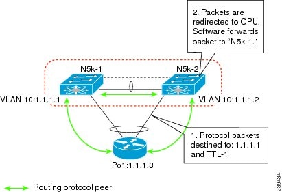
This topology is supported for unicast traffic but not for multicast traffic. In this topology, we recommend that you use Layer 3 interfaces instead of vPC interfaces to connect routers to Cisco Nexus 5500 Platform switches whenever possible.
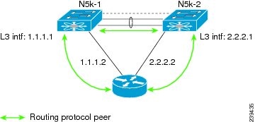
Figure 2-7, shows the recommended topology for connectivity of routers to a vPC domain. The router connects with Layer 3 interfaces 1.1.1.2 and 2.2.2.2 to the two vPC peers and these interfaces are not part of a vPC port channel.
Figure 2-7 Connecting a Router to a vPC Domain Using Layer 3 Interfaces
Dedicated VRF For a Keepalive Interface
Beginning in Cisco NX-OS Release 5.0(3)N1(1b), the Cisco Nexus 5500 Platform switch supports VRF lite with a Layer 3 module and Enterprise license and you can create a VRF and assign the interface to a VRF. Prior to this release, two VRFs were created by default: the VRF management and VRF default. The management interface(mgmt0) and all SVI interfaces resided in the VRF management and VRF default respectively.
We recommend that you use an out-of-band management interface (mgmt0) as a vPC keepalive interface although you have the option to use the front-panel data port as a vPC keepalive interface. When you choose to use the front panel 10-Gigabit Ethernet port as the vPC keepalive interface, you should create a separate VRF for vPC keepalive packets when Layer 3 is enabled with vPC. This process eliminates the possibility of disrupting the vPC keepalive link by the wrong routes learned by a dynamic routing protocol.
This example shows how to configure a new VRF named vpc_keepalive for the vPC keepalive link and how to display the vPC peer keepalive configuration:
The services provided by the Cisco Nexus 5500 Platform switch, such as Ping, SSH, Telnet, and RADIUS, are VRF-aware. You must specify the VRF name in the CLI in order to use the correct routing table.
vPC Consistency Check for Layer 3 Parameters
In a vPC topology, vPC peer switches run routing protocols independently and they maintain the routing table independently. Consistency checks are not performed to verify that Layer 3 configurations in the vPC domain are configured symmetrically.
For example, if you configure a router ACL (RACL) on one SVI and you do not configure the router on the corresponding SVI on the vPC peer, a syslog message is not displayed. You must configure the RACL on both devices. This is consistent with the operation of independent routing devices.
Similarly, if you configure peer gateway on one vPC peer and you want the same peer gateway configuration on the other vPC peer, you must configure the peer gateway on the vPC peer.
To confirm that a vPC domain is correctly configured for Layer 3 operations, the following configurations must be consistent:
Multicast Interaction in a vPC Topology
This section includes the following topics:
Unsupported Multicast Topology
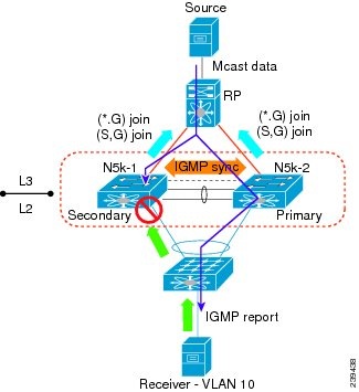
Figure 2-8 shows an unsupported multicast topology in a vPC configuration.
Figure 2-8 Unsupported Multicast Topology with a vPC
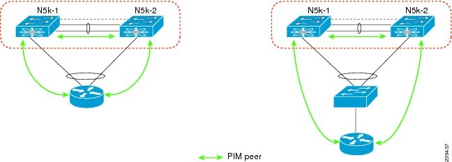
When a PIM router is connected to Cisco Nexus 5500 Platform switches in a vPC topology, the PIM join messages are received only by one switch. The multicast data might be received by the other switch.
Note![]() Multicast forwarding in this topology does not work.
Multicast forwarding in this topology does not work.
Multicast Routing Table Size
When you enable a vPC on a Nexus 5500 Platform switch, one multicast route (*,G) or (S,G) requires two entries in the routing table; therefore, the multicast routing table size is half the size of what is supported in topologies where vPC is not enabled.
Beginning with Cisco NX-OS Release 5.0(3)N1(1b), the Cisco Nexus 5500 Platform multicast routing table size is 2000 entries in non-vPC topologies and 1000 entries in vPC topologies.
Faster Convergence with the Prebuilt Source Tree
In a non-vPC topology, only the designated router (DR) can join the source tree. In a vPC topology, when a receiver is connected to a Cisco Nexus 5500 Platform switch or Fabric Extender (FEX) via vPC, both peer switches initiate a PIM (S,G) join toward the source DR. In a topology where both vPC peer switches have equal costs to the source, the vPC primary switch wins the assert and forwards multicast traffic for receivers connected to the Nexus 5500 Platform switch or FEX using the vPC. The vPC secondary switch also joins the source tree and pulls the multicast data. To prevent data duplication, the vPC secondary switch drops the data due to an empty outgoing interface (OIF) list. Once the vPC secondary switch detects the failure of the vPC primary switch, it adds the receiver VLAN to the OIF list and starts to forward the multicast traffic immediately. Because the vPC secondary switch joins the source tree before the failure, it does not need to initiate the (S,G) join and waits for the tree to be built. As a result, it improves the convergence time in the case of a failure with the active multicast traffic forwarder.
Figure 2-9 shows one receiver that is connected to a dual-homed FEX. The source and Rendezvous Point (RP) are in the Layer 3 network. N5k-2, which is the VPC primary switch, is the multicast traffic forwarder for receivers in VLAN 10.
Figure 2-9 vPC Switch as the Receiver Designated Router
This example shows the output of the multicast routing table and VLAN 10 appears in the OIF list of (S,G) entry on N5k-2. N5k-1 joins the source tree but its OIF list remains empty.
The multicast forwarding algorithm applies to all hosts that are connected to the Cisco Nexus 5500 Platform switch or the FEX in a VPC topology, including hosts directly connected to the switch or hosts connected to straight-through FEX topology.
Using a vPC Switch as a Designated Router (PIM DR)
This section includes the following topics:
DR Election and Source Registration
In vPC topologies, a DR election occurs based on the DR priority and the IP address. The elected DR is responsible for sending the source registration toward the RP. When multicast traffic from a directly connected source is received by the non-DR peer switch, the peer switch notifies the DR switch using a Cisco Fabric Services (CFS) message about the source and group address. The DR generates source registration packets to the rendezvous point (RP).
Multicast Data Forwarding
The Cisco Nexus 5500 Platform switch implements a dual-DR mechanism where both vPC peer switches can forward multicast traffic from directly connected sources. The data forwarding rules are as follows:
- The peer switch receives multicast packets from a directly connected source, performs an mroute lookup, and replicates packets for each interface in the OIF list.
- If the OIF is a VLAN trunked over a vPC peer link, one copy is sent over to the peer link for each VLAN that is present in the OIF list. By default, the vPC peer link is considered an mrouter port. Therefore, the multicast packets are sent over to the peer link for each receiving VLAN. You can use the no ip igmp snooping mrouter vpc-peer link command to avoid sending multicast traffic over a peer link for each receiver VLAN when there are no orphan ports.
This example shows how to avoid sending the multicast traffic in this scenario:
With the above CLI configured, the multicast packet is only sent to peer link for VLANs that have orphan ports.
This example shows how to display the list of all orphan ports:
Note![]() As of Cisco NX-OS Release 5.0(3)N1(1b), the no ip igmp snooping mrouter vpc-peer link command cannot be applied with FEX dual-homed topologies due to a software limitation. The command is used only for interfaces on a Cisco Nexus 5500 Platform switch. This software limitation will be removed in a future software release.
As of Cisco NX-OS Release 5.0(3)N1(1b), the no ip igmp snooping mrouter vpc-peer link command cannot be applied with FEX dual-homed topologies due to a software limitation. The command is used only for interfaces on a Cisco Nexus 5500 Platform switch. This software limitation will be removed in a future software release.
One post-routed multicast packet is sent to a vPC peer link using a reserved VLAN. To configure the reserved VLAN, use the follow commands:
One reserved VLAN is required for each VRF. Without these commands, the receivers in non-vPC VLAN and the receivers connected to Layer 3 interfaces may not receive multicast traffic. The non-vPC VLANs are the VLANs that are not trunked over a peer link.
Multicast traffic that is received over a peer link (with a VLAN ID other than the reserved VLAN ID) is not routed. The multicast traffic is treated as Layer 2 frames that are sent to orphan ports only and not to vPC member ports. The multicast traffic that is received over a peer link with a reserved VLAN ID is routed to a non-vPC VLAN (shown as VLAN 13 in Figure 2-10) and receivers behind the Layer 3 interface. The receivers behind the Layer 3 interface can be hosts directly connected to the Cisco Nexus 5500 Platform switch using Layer 3 interfaces or a router joins the source tree.
Figure 2-10 shows the multicast forwarding rules in a vPC dual-DR topology. In this topology, the source in VLAN 10 and receivers in VLAN 11 and VLAN 12 are the vPC hosts (although in this example they are hosts behind a dual-homed FEX topology where the same rule applies to hosts directly to a Cisco Nexus 5500 Platform switch in a vPC topology). VLAN 13 is a non-vPC VLAN and resides only on N5k-2.
Figure 2-10 Multicast Data Forwarding
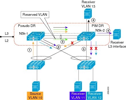
The forwarding process is as follows:
1.![]() IGMP joins from the hosts are synchronized between the two vPC peer switches. N5k-2 is elected as the PIM DR for VLAN 10. Multicast traffic is sent over to N5k-1.
IGMP joins from the hosts are synchronized between the two vPC peer switches. N5k-2 is elected as the PIM DR for VLAN 10. Multicast traffic is sent over to N5k-1.
2.![]() The routing engine of N5k-1 performs an mroute lookup and replicates packets to VLAN 11 and VLAN 12. The data packets for VLAN 11 and VLAN 12 are sent to the FEX which in turn sends packets to the two receivers;
The routing engine of N5k-1 performs an mroute lookup and replicates packets to VLAN 11 and VLAN 12. The data packets for VLAN 11 and VLAN 12 are sent to the FEX which in turn sends packets to the two receivers;
3.![]() By default, the replicated packets are sent to the vPC peer link for the source VLAN as well as each receiver VLAN (VLAN 10, VLAN 11, and VLAN 12) in this example. When you use the no ip igmp snooping mrouter vpc-peer-link command, the multicast packets are not sent to the peer link for VLAN 10, VLAN 11, and VLAN 12 because there are no orphan ports. One copy of the packets is sent to the peer link with the reserved VLAN 3000 which was configured using the vpc bind-vrf default vlan 3000 command.
By default, the replicated packets are sent to the vPC peer link for the source VLAN as well as each receiver VLAN (VLAN 10, VLAN 11, and VLAN 12) in this example. When you use the no ip igmp snooping mrouter vpc-peer-link command, the multicast packets are not sent to the peer link for VLAN 10, VLAN 11, and VLAN 12 because there are no orphan ports. One copy of the packets is sent to the peer link with the reserved VLAN 3000 which was configured using the vpc bind-vrf default vlan 3000 command.
Note![]() In Cisco NX-OS Release 5.0(3)N1(1b), the no ip igmp snooping mrouter vpc-peer-link command cannot be applied with a FEX dual-homed topology.
In Cisco NX-OS Release 5.0(3)N1(1b), the no ip igmp snooping mrouter vpc-peer-link command cannot be applied with a FEX dual-homed topology.
4.![]() For the multicast traffic received from the peer link, if the VLAN ID is the reserved VLAN ID 3000, the N5k-2 route engine performs a Layer 3 lookup and replicates packets to VLAN 13 (a non-vPC VLAN) and receivers behind Layer 3 interfaces.
For the multicast traffic received from the peer link, if the VLAN ID is the reserved VLAN ID 3000, the N5k-2 route engine performs a Layer 3 lookup and replicates packets to VLAN 13 (a non-vPC VLAN) and receivers behind Layer 3 interfaces.
5.![]() For the multicast packets received over the peer link, VLAN 10, VLAN 11, and VLAN 12 are dropped by N5k-2 to prevent duplicated packets being sent to the vPC hosts. If any orphan ports are in VLAN 10, VLAN 11, and VLAN 12, the packets are bridged to the orphan ports.
For the multicast packets received over the peer link, VLAN 10, VLAN 11, and VLAN 12 are dropped by N5k-2 to prevent duplicated packets being sent to the vPC hosts. If any orphan ports are in VLAN 10, VLAN 11, and VLAN 12, the packets are bridged to the orphan ports.
Software Upgrade and Downgrade Impact
In Cisco NX-OS Release 5.0(3)N1(1b), the Cisco Nexus 5500 Platform switch does not support ISSUs when Layer 3 modules are installed and Layer 3 features are enabled. Use the install all command and the show install all impact command to determine the impact of the software upgrade and to indicate whether the software upgrade with Layer 3 features enabled will be disruptive and would require a switch and FEX reload.
show install all impact kickstart
This example shows the output of the show install all command:
You can perform a nondisruptive ISSU from an earlier release to NX-OS Release 5.0(3)N1(1b) when upgrading without Layer 3 features enabled.
show spanning-tree issu-impact
To verify that the current STP topology is consistent with ISSU requirements, use the show spanning-tree issu-impact command to display the STP configuration and whether or not there are potential STP issues.
This example shows how to display information about the STP impact when performing an ISSU:
For information on upgrade procedures, see the Cisco Nexus 5000 Series NX-OS Upgrade and Downgrade Guide.
 Feedback