- Preface
- New and Changed Information
- Overview
- Configuring Ethernet Interfaces
- Configuring VLANs
- Configuring Private VLANs
- Configuring Access and Trunk Interfaces
- Configuring Port Channels
- Configuring Virtual Port Channels
- Configuring Enhanced Virtual Port Channels
- Configuring Rapid PVST+
- Configuring Multiple Spanning Tree
- Configuring STP Extensions
- Configuring Flex Links
- Configuring LLDP
- Configuring MAC Address Tables
- Configuring IGMP Snooping
- Configuring MVR
- Configuring Traffic Storm Control
- Configuring the Fabric Extender
- Index
- Information About the Cisco Nexus 2000 Series Fabric Extender
- Fabric Extender Terminology
- Fabric Extender Features
- Oversubscription
- Management Model
- Forwarding Model
- Connection Model
- Port Numbering Convention
- Fabric Extender Image Management
- Fabric Extender Hardware
- Associating a Fabric Extender to a Fabric Interface
- Configuring Fabric Extender Global Features
- Enabling the Fabric Extender Locator LED
- Redistributing the Links
Configuring the Fabric Extender
This chapter contains the following sections:
- Information About the Cisco Nexus 2000 Series Fabric Extender
- Fabric Extender Terminology
- Fabric Extender Features
- Oversubscription
- Management Model
- Forwarding Model
- Connection Model
- Port Numbering Convention
- Fabric Extender Image Management
- Fabric Extender Hardware
- Associating a Fabric Extender to a Fabric Interface
- Configuring Fabric Extender Global Features
- Enabling the Fabric Extender Locator LED
- Redistributing the Links
- Verifying the Fabric Extender Configuration
- Verifying the Chassis Management Information
- Configuring the Cisco Nexus N2248TP-E Fabric Extender
Information About the Cisco Nexus 2000 Series Fabric Extender
The Cisco Nexus 2000 Series Fabric Extender, also known as FEX, is a highly scalable and flexible server networking solution that works with Cisco Nexus Series devices to provide high-density, low-cost connectivity for server aggregation. Scaling across 1-Gigabit Ethernet, 10-Gigabit Ethernet, unified fabric, rack, and blade server environments, the Fabric Extender is designed to simplify data center architecture and operations.
The Fabric Extender integrates with its parent switch, which is a Cisco Nexus Series device, to allow automatic provisioning and configuration taken from the settings on the parent device. This integration allows large numbers of servers and hosts to be supported by using the same feature set as the parent device with a single management domain. The Fabric Extender and its parent switch enable a large multipath, loop-free, active-active data center topology without the use of the Spanning Tree Protocol (STP).
The Cisco Nexus 2000 Series Fabric Extender forwards all traffic to its parent Cisco Nexus Series device over 10-Gigabit Ethernet fabric uplinks, which allows all traffic to be inspected by policies established on the Cisco Nexus Series device.
No software is included with the Fabric Extender. The software is automatically downloaded and upgraded from its parent device.
Fabric Extender Terminology
Some terms used in this document are as follows:
-
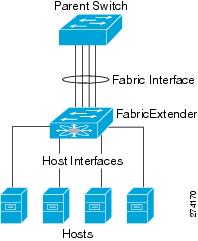
Fabric interface—A 10-Gigabit Ethernet uplink port that is designated for connection from the Fabric Extender to its parent switch. A fabric interface cannot be used for any other purpose. It must be directly connected to the parent switch.

Note
A fabric interface includes the corresponding interface on the parent switch. This interface is enabled when you enter the switchport mode fex-fabric command.
-
Port channel fabric interface—A port channel uplink connection from the Fabric Extender to its parent switch. This connection consists of fabric interfaces that are bundled into a single logical channel.
-
Host interface—An Ethernet host interface for connection to a server or host system.
Note
Do not connect a bridge or switch to a host interface. These interfaces are designed to provide end host or server connectivity.
Note
On Cisco Nexus 2348TQ and Nexus 2348UPQ FEX, if a port channel is used to connect a parent switch with a Fabric Extender device, the port channels can have maximum of 8 ports.
The Nexus 2348 FEX devices have a total of 6 * 40 Gigabit Ethernet uplink ports towards the parent switch. If these are used with native 40G uplinks port on a parent switch, then there is no limitation. All 6 ports can be used in either single homed or dual homed configuration. You can also use 40 Gigabit Ethernet uplink ports on the N2348 Fabric Extender device with 10 Gigabit Ethernet ports on the parent switch when used with the appropriate cabling. A maximum of 8 ports can be added to the port channel between the parent switch and Fabric Extender device. If it is a dual homed setup, VPC to the Fabric Extender device, only 4 ports per switch are allowed in the port channel.
-
Port channel host interface—A port channel host interface for connection to a server or host system.
Fabric Extender Features
The Cisco Nexus 2000 Series Fabric Extender allows a single switch—and a single consistent set of switch features—to be supported across a large number of hosts and servers. By supporting a large server-domain under a single management entity, policies can be enforced more efficiently.
Some of the features of the parent switch cannot be extended onto the Fabric Extender.
- Layer 2 Host Interfaces
- Host Port Channel
- VLANs and Private VLANs
- Virtual Port Channels
- Fibre Channel over Ethernet Support
- Protocol Offload
- Quality of Service
- Access Control Lists
- IGMP Snooping
- Switched Port Analyzer
- Fabric Interface Features
Layer 2 Host Interfaces
The Fabric Extender provides connectivity for computer hosts and other edge devices in the network fabric.
-
All Fabric Extender host interfaces run as spanning tree edge ports with BPDU Guard enabled and you cannot configure them as spanning tree network ports.
-
You can connect servers that use active/standby teaming, 802.3ad port channels, or other host-based link redundancy mechanisms to Fabric Extender host interfaces.
-
Any device that is running spanning tree connected to a Fabric Extender host interface results in that host interface being placed in an error-disabled state when a BPDU is received.
-
You can connect only virtual switches that leverages a link redundancy mechanism not dependent on spanning tree such as Cisco FlexLink or vPC (with the BPDU Filter enabled) to a Fabric Extender host interface. Because spanning tree is not used to eliminate loops, you should ensure a loop-free topology below the Fabric Extender host interfaces.
You can enable host interfaces to accept Cisco Discovery Protocol (CDP) packets. This protocol only works when it is enabled for both ends of a link.
Note | CDP is not supported on fabric interfaces when the Fabric Extender is configured in a virtual port channel (vPC) topology. |
Ingress and egress packet counters are provided on each host interface.
For more information about BPDU Guard, see Understanding BPDU Guard .
Host Port Channel
The Cisco Nexus 2248TP, Cisco Nexus 2232PP, Cisco Nexus 2224TP, , Cisco Nexus B22 Fabric Extender for Fujitsu (N2K-B22FTS-P), Cisco Nexus B22 Fabric Extender for Dell (N2K-B22DELL-P), and Cisco Nexus B22 Fabric Extender for HP (N2K-B22HP-P) support port channel host interface configurations. Up to eight interfaces can be combined in an port channel. The port channel can be configured with or without LACP.
VLANs and Private VLANs
The Fabric Extender supports Layer 2 VLAN trunks and IEEE 802.1Q VLAN encapsulation. Host interfaces can be members of private VLANs with the following restrictions:
-
You can configure a host interface as an isolated or community access port only.
-
You cannot configure a host interface as a promiscuous port.
-
You cannot configure a host interface as a private VLAN trunk port.
For more information about VLANs, see the chapter in this guide on Configuring VLANs.
Virtual Port Channels
With a virtual port channel (vPC), you can configure topologies where a Cisco Nexus Fabric Extender is connected to a pair of parent switches or a pair of Fabric Extenders are connected to a single parent switch. The vPC can provide multipath connections, which allow you to create redundancy between the nodes on your network.
Note | A port channel between two FEXs that are connected to the same Cisco Nexus device is not supported. Virtual port channels (vPCs) cannot span two different FEXs when connected to the same Cisco Nexus device. |
The following vPC topologies are possible with the Fabric Extender:
-
The parent switches are connected single homed to Fabric Extenders that are subsequently connected to servers with dual interfaces (see the following figure).
Figure 1. Single Homed Fabric Extender vPC Topology 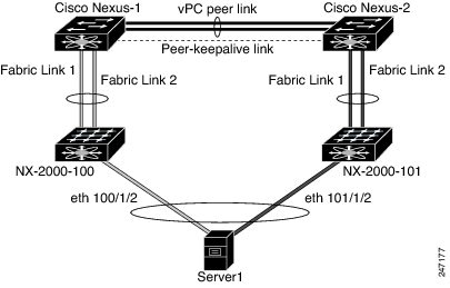
-
The Fabric Extender is connected dual homed to two upstream parent switches and connected downstream to single homed servers (see the following figure).
Figure 2. Dual Homed Fabric Extender vPC Topology 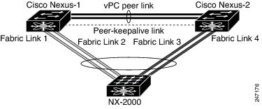
This configuration is also called an Active-Active topology.
Note | Port channels between two Fabric Extenders connected to the same Cisco Nexus device is not supported vPCs cannot span two different Fabric Extenders that are connected to the same physical Cisco Nexus device. |
Fibre Channel over Ethernet Support
The Cisco Nexus 2232PP supports Fibre Channel over Ethernet (FCoE) with the following restrictions:
Only FCoE Initialization Protocol (FIP) enabled converged network adapters (CNAs) are supported on the Fabric Extender.
Binding to a port channel is limited to only one member in the port channel.
For configuration details, see the Fibre Channel over Ethernet Configuration Guide for the Nexus software release that you are using. The available versions of this document can be found at the following URL: http://www.cisco.com/en/US/products/ps9670/products_installation_and_configuration_guides_list.html.
Protocol Offload
To reduce the load on the control plane of the Cisco Nexus Series device, Cisco NX-OS allows you to offload link-level protocol processing to the Fabric Extender CPU. The following protocols are supported:
Quality of Service
Access Control Lists
The Fabric Extender supports the full range of ingress access control lists (ACLs) that are available on its parent Cisco Nexus Series device.
IGMP Snooping
Switched Port Analyzer
Fabric Interface Features
Oversubscription
Management Model
The Cisco Nexus 2000 Series Fabric Extender is managed by its parent switch over the fabric interfaces through a zero-touch configuration model. The switch discovers the Fabric Extender by detecting the fabric interfaces of the Fabric Extender.
After discovery, if the Fabric Extender has been correctly associated with the parent switch, the following operations are performed:
-
The switch checks the software image compatibility and upgrades the Fabric Extender if necessary.
-
The switch and Fabric Extender establish in-band IP connectivity with each other.
The switch assigns an IP address in the range of loopback addresses (127.15.1.0/24) to the Fabric Extender to avoid conflicts with IP addresses that might be in use on the network.
-
The switch pushes the configuration data to the Fabric Extender. The Fabric Extender does not store any configuration locally.
-
The Fabric Extender updates the switch with its operational status. All Fabric Extender information is displayed using the switch commands for monitoring and troubleshooting.
Forwarding Model
The Cisco Nexus 2000 Series Fabric Extender does not perform any local switching. All traffic is sent to the parent switch that provides central forwarding and policy enforcement, including host-to-host communications between two systems that are connected to the same Fabric Extender as shown in the following figure.
The forwarding model facilitates feature consistency between the Fabric Extender and its parent Cisco Nexus Series device.
Note | The Fabric Extender provides end-host connectivity into the network fabric. As a result, BPDU Guard is enabled on all its host interfaces. If you connect a bridge or switch to a host interface, that interface is placed in an error-disabled state when a BPDU is received. You cannot disable BPDU Guard on the host interfaces of the Fabric Extender. |
The Fabric Extender supports egress multicast replication from the network to the host. Packets that are sent from the parent switch for multicast addresses attached to the Fabric Extender are replicated by the Fabric Extender ASICs and are then sent to corresponding hosts.
Connection Model
Two methods (the static pinning fabric interface connection and the Port Channel fabric interface connection) allow the traffic from an end host to the parent switch to be distributed when going through the Cisco Nexus 2000 Series Fabric Extender.
Static Pinning Fabric Interface Connection
To provide a deterministic relationship between the host interfaces and the parent switch, you can configure the Fabric Extender to use individual fabric interface connections. This configuration connects the 10-Gigabit Ethernet fabric interfaces as shown in the following figure. You can use any number of fabric interfaces up to the maximum available on the model of the Fabric Extender.
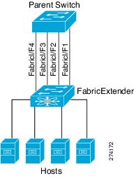
When the Fabric Extender is brought up, its host interfaces are distributed equally among the available fabric interfaces. As a result, the bandwidth that is dedicated to each end host toward the parent switch is never changed by the switch but instead is always specified by you.
Note | If a fabric interface fails, all its associated host interfaces are brought down and remain down until the fabric interface is restored. |
You must use the pinning max-links command to create a number of pinned fabric interface connections so that the parent switch can determine a distribution of host interfaces. The host interfaces are divided by the number of the max-links and distributed accordingly. The default value is max-links 1.
 Caution | Changing the value of the max-links is disruptive; all the host interfaces on the Fabric Extender are brought down and back up as the parent switch reassigns its static pinning. |
The pinning order of the host interfaces is initially determined by the order in which the fabric interfaces were configured. When the parent switch is restarted, the configured fabric interfaces are pinned to the host interfaces in an ascending order by the port number of the fabric interface.
To guarantee a deterministic and sticky association across a reboot, you can manually redistribute the pinning.
Note | The redistribution of the host interfaces will always be in an ascending order by the port number of the fabric interface. |
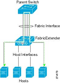
Port Channel Fabric Interface Connection
To provide load balancing between the host interfaces and the parent switch, you can configure the Fabric Extender to use a port channel fabric interface connection. This connection bundles 10-Gigabit Ethernet fabric interfaces into a single logical channel as shown in the following figure.
When you configure the Fabric Extender to use a port channel fabric interface connection to its parent switch, the switch load balances the traffic from the hosts that are connected to the host interface ports by using the following load-balancing criteria to select the link:
-
For a Layer 2 frame, the switch uses the source and destination MAC addresses.
-
For a Layer 3 frame, the switch uses the source and destination MAC addresses and the source and destination IP addresses.
Note | A fabric interface that fails in the port channel does not trigger a change to the host interfaces. Traffic is automatically redistributed across the remaining links in the port channel fabric interface. If all links in the fabric port channel go down, all host interfaces on the FEX are set to the down state. |
Port Numbering Convention
Fabric Extender Image Management
No software ships with the Cisco Nexus 2000 Series Fabric Extender. The Fabric Extender image is bundled into the system image of the parent switch. The image is automatically verified and updated (if required) during the association process between the parent switch and the Fabric Extender.
When you enter the install all command, it upgrades the software on the parent Cisco Nexus Series switch and also upgrades the software on any attached Fabric Extender. To minimize downtime as much as possible, the Fabric Extender remains online while the installation process loads its new software image. Once the software image has successfully loaded, the parent switch and the Fabric Extender both automatically reboot.
This process is required to maintain version compatibility between the parent switch and the Fabric Extender.
Fabric Extender Hardware
The Cisco Nexus 2000 Series Fabric Extender architecture allows hardware configurations with various host interface counts and speeds.
Chassis
The Cisco Nexus 2000 Series Fabric Extender is a 1 RU chassis that is designed for rack mounting. The chassis supports redundant hot-swappable fans and power supplies.
Ethernet Interfaces
There are four models of the Cisco Nexus 2000 Series Fabric Extender:
The Cisco Nexus 2148T has 48 1000BASE-T Ethernet host interfaces for its downlink connection to servers or hosts and 4 10-Gigabit Ethernet fabric interfaces with SFP+ interface adapters for its uplink connection to the parent switch.
The Cisco Nexus 2224TP has 24 100BASE-T/1000Base-T Ethernet host interfaces for its downlink connection to servers or hosts and 2 10-Gigabit Ethernet fabric interfaces with SFP+ interface adapters for its uplink connection to the parent switch.
The Cisco Nexus 2232PP has 32 10-Gigabit Ethernet host interfaces with SFP+ interface adapters and 8 10-Gigabit Ethernet fabric interfaces with SFP+ interface adapters for its uplink connection to the parent switch.
The Cisco Nexus 2248TP has 48 100BASE-T/1000Base-T Ethernet host interfaces for its downlink connection to servers or hosts and 4 10-Gigabit Ethernet fabric interfaces with SFP+ interface adapters for its uplink connection to the parent switch.
The Cisco Nexus 2248TP-E has all the features of the Cisco Nexus 2248TP with these additional features:
The Cisco Nexus B22 Fabric Extender for HP (NB22HP) has 16 1G/10-Gigabit Ethernet host interfaces. All host interfaces use all of the available fabric interfaces.
The Cisco Nexus B22 Fabric Extender for Fujitsu (NB22FTS) has 16 10-Gigabit Ethernet host interfaces. All host interfaces use all of the available fabric interfaces.
The Cisco Nexus B22 Fabric Extender for Dell (NB22DELL) has 16 1G/10-Gigabit Ethernet host interfaces. All host interfaces use all of the available fabric interfaces.
Associating a Fabric Extender to a Fabric Interface
- Associating a Fabric Extender to an Ethernet Interface
- Associating a Fabric Extender to a Port Channel
- Disassociating a Fabric Extender from an Interface
Associating a Fabric Extender to an Ethernet Interface
Ensure that you have enabled the Fabric Extender feature.
1.
configure terminal
2.
interface ethernet
slot/port
3.
switchport mode fex-fabric
4.
fex associate
FEX-number
5.
(Optional)
show interface ethernet
port/slot
fex-intf
DETAILED STEPS
This example shows how to associate the Fabric Extender to an Ethernet interface on the parent device:
switch# configure terminal switch(config)# interface ethernet 1/40 switch(config-if)# switchport mode fex-fabric switch(config-if)# fex associate 101 switch(config)#
This example shows how to display the association of the Fabric Extender and the parent device:
switch# show interface ethernet 1/40 fex-intf
Fabric           FEX
Interface        Interfaces
---------------------------------------------------
Eth1/40          Eth101/1/48   Eth101/1/47   Eth101/1/46   Eth101/1/45
                 Eth101/1/44   Eth101/1/43   Eth101/1/42   Eth101/1/41
                 Eth101/1/40   Eth101/1/39   Eth101/1/38   Eth101/1/37
                 Eth101/1/36   Eth101/1/35   Eth101/1/34   Eth101/1/33
                 Eth101/1/32   Eth101/1/31   Eth101/1/30   Eth101/1/29
                 Eth101/1/28   Eth101/1/27   Eth101/1/26   Eth101/1/25
                 Eth101/1/24   Eth101/1/23   Eth101/1/22   Eth101/1/21
                 Eth101/1/20   Eth101/1/19   Eth101/1/18   Eth101/1/17
                 Eth101/1/16   Eth101/1/15   Eth101/1/14   Eth101/1/13
                 Eth101/1/12   Eth101/1/11   Eth101/1/10   Eth101/1/9
                 Eth101/1/8    Eth101/1/7    Eth101/1/6    Eth101/1/5
                 Eth101/1/4    Eth101/1/3    Eth101/1/2    Eth101/1/1
Associating a Fabric Extender to a Port Channel
Ensure that you have enabled the Fabric Extender feature.
1.
configure terminal
2.
interface port-channel
channel
3.
switchport mode
fex-fabric
4.
fex associate
FEX-number
5.
(Optional)
show interface
port-channel
channel
fex-intf
DETAILED STEPS
This example shows how to associate the Fabric Extender to a port channel interface on the parent device:
switch# configure terminal switch(config)# interface ethernet 1/28 switch(config-if)# channel-group 4 switch(config-if)# no shutdown switch(config-if)# exit switch(config)# interface ethernet 1/29 switch(config-if)# channel-group 4 switch(config-if)# no shutdown switch(config-if)# exit switch(config)# interface ethernet 1/30 switch(config-if)# channel-group 4 switch(config-if)# no shutdown switch(config-if)# exit switch(config)# interface ethernet 1/31 switch(config-if)# channel-group 4 switch(config-if)# no shutdown switch(config-if)# exit switch(config)# interface port-channel 4 switch(config-if)# switchport switch(config-if)# switchport mode fex-fabric switch(config-if)# fex associate 101
 Tip | As a best practice, only enter the fex associate command from the port channel interface, not from the physical interface. |
Note | When adding physical interfaces to port channels, all configurations on the port channel and physical interface must match. |
This example shows how to display the association of the Fabric Extender and the parent device:
switch# show interface port-channel 4 fex-intf
Fabric           FEX
Interface        Interfaces
---------------------------------------------------
Po4              Eth101/1/48   Eth101/1/47   Eth101/1/46   Eth101/1/45
                 Eth101/1/44   Eth101/1/43   Eth101/1/42   Eth101/1/41
                 Eth101/1/40   Eth101/1/39   Eth101/1/38   Eth101/1/37
                 Eth101/1/36   Eth101/1/35   Eth101/1/34   Eth101/1/33
                 Eth101/1/32   Eth101/1/31   Eth101/1/30   Eth101/1/29
                 Eth101/1/28   Eth101/1/27   Eth101/1/26   Eth101/1/25
                 Eth101/1/24   Eth101/1/23   Eth101/1/22   Eth101/1/21
                 Eth101/1/20   Eth101/1/19   Eth101/1/18   Eth101/1/17
                 Eth101/1/16   Eth101/1/15   Eth101/1/14   Eth101/1/13
                 Eth101/1/12   Eth101/1/11   Eth101/1/10   Eth101/1/9
                 Eth101/1/8    Eth101/1/7    Eth101/1/6    Eth101/1/5
                 Eth101/1/4    Eth101/1/3    Eth101/1/2    Eth101/1/1
Disassociating a Fabric Extender from an Interface
Ensure that you have enabled the Fabric Extender feature.
1.
configure terminal
2.
interface {ethernet
slot/port |
port-channel
channel}
3.
no fex associate
DETAILED STEPS
Configuring Fabric Extender Global Features
You can configure global features on the Fabric Extender.
Ensure that you have enabled the Fabric Extender feature set.
1.
configure terminal
2.
fex
FEX-number
3.
(Optional)
description
desc
4.
(Optional)
no description
5.
(Optional) no type
6.
(Optional)
pinning max-links
uplinks
7.
(Optional)
no pinning max-links
8.
(Optional)
serial
serial
9.
(Optional)
no serial
DETAILED STEPS
Enabling the Fabric Extender Locator LED
The locator beacon LED on the Fabric Extender allows you to locate a specific Fabric Extender in a rack.
1.
locator-led fex FEX-number
2.
(Optional) no locator-led fex FEX-number
DETAILED STEPS
| Command or Action | Purpose |
|---|
Redistributing the Links
When you provision the Fabric Extender with statically pinned interfaces, the downlink host interfaces on the Fabric Extender are pinned to the fabric interfaces in the order they were initially configured. If you want to maintain a specific relationship of host interfaces to fabric interface across reboots, you should repin the links.
You may want to perform this function in these two situations:
Changing the Number of Links
If you initially configured a specific port on the parent switch, for example port 33, as your only fabric interface, all 48 host interfaces are pinned to this port. If you provision another port, for example 35, then you must enter the pinning max-links 2 command to redistribute the host interfaces. All host interfaces are brought down and host interfaces 1 to 24 are pinned to fabric interface 33 and host interfaces 25 to 48 are pinned to fabric interface 35.
Maintaining the Pinning Order
The pinning order of the host interfaces is initially determined by the order in which the fabric interfaces were configured. In this example, four fabric interfaces were configured in the following order:
switch# show interface ethernet 1/35 fex-intf
Fabric FEX
Interface Interfaces
---------------------------------------------------
Eth1/35 Eth101/1/12 Eth101/1/11 Eth101/1/10 Eth101/1/9
Eth101/1/8 Eth101/1/7 Eth101/1/6 Eth101/1/5
Eth101/1/4 Eth101/1/3 Eth101/1/2 Eth101/1/1
switch# show interface ethernet 1/33 fex-intf
Fabric FEX
Interface Interfaces
---------------------------------------------------
Eth1/33 Eth101/1/24 Eth101/1/23 Eth101/1/22 Eth101/1/21
Eth101/1/20 Eth101/1/19 Eth101/1/18 Eth101/1/17
Eth101/1/16 Eth101/1/15 Eth101/1/14 Eth101/1/13
switch# show interface ethernet 1/38 fex-intf
Fabric FEX
Interface Interfaces
---------------------------------------------------
Eth1/38 Eth101/1/36 Eth101/1/35 Eth101/1/34 Eth101/1/33
Eth101/1/32 Eth101/1/31 Eth101/1/30 Eth101/1/29
Eth101/1/28 Eth101/1/27 Eth101/1/26 Eth101/1/25
switch# show interface ethernet 1/40 fex-intf
Fabric FEX
Interface Interfaces
---------------------------------------------------
Eth1/40 Eth101/1/48 Eth101/1/47 Eth101/1/46 Eth101/1/45
Eth101/1/44 Eth101/1/43 Eth101/1/42 Eth101/1/41
Eth101/1/40 Eth101/1/39 Eth101/1/38 Eth101/1/37
The next time that you reboot the Fabric Extender, the configured fabric interfaces are pinned to the host interfaces in an ascending order by port number of the fabric interface. If you want to configure the same fixed distribution of host interfaces without restarting the Fabric Extender, enter the fex pinning redistribute command.
Redistributing Host Interfaces
Caution | This command disrupts all the host interface ports of the Fabric Extender. |
1.
configure terminal
2.
fex pinning redistribute
FEX-number
DETAILED STEPS
| Command or Action | Purpose | |
|---|---|---|
| Step 1 | configure terminal
Example: switch# configure terminal switch(config)# |
Enters global configuration mode. |
| Step 2 | fex pinning redistribute
FEX-number Example: switch(config) # fex pinning redistribute 101 switch(config) # | Redistributes the host connections. The range of FEX-number is from 100 to 199. |
Verifying the Fabric Extender Configuration
Use the following commands to display configuration information about the defined interfaces on a Fabric Extender:
Command or Action |
Purpose |
|---|---|
| show fex [FEX-number] [detail] | Displays information about a specific Fabric Extender or all attached units. |
| show interface type number fex-intf | Displays the Fabric Extender ports that are pinned to a specific switch interface. |
| show interface fex-fabric | Displays the switch interfaces that have detected a Fabric Extender uplink. |
| show interface ethernet number transceiver [fex-fabric] | Displays the SFP+ transceiver and diagnostic optical monitoring (DOM) information for the Fabric Extender uplinks. |
| show feature-set | Displays the status of the feature sets on the device. |
Configuration Examples for the Fabric Extender
This example shows how to display all the attached Fabric Extender units:
switch# show fex FEX FEX FEX FEX Number Description State Model Serial ------------------------------------------------------------------------ 100 FEX0100 Online N2K-C2248TP-1GE JAF1339BDSK 101 FEX0101 Online N2K-C2232P-10GE JAF1333ADDD 102 FEX0102 Online N2K-C2232P-10GE JAS12334ABC
This example shows how to display the detailed status of a specific Fabric Extender:
switch# show fex 100 detail
FEX: 100 Description: FEX0100 state: Online
FEX version: 5.0(2)N1(1) [Switch version: 5.0(2)N1(1)]
FEX Interim version: 5.0(2)N1(0.205)
Switch Interim version: 5.0(2)N1(0.205)
Extender Model: N2K-C2224TP-1GE, Extender Serial: JAF1427BQLG
Part No: 73-13373-01
Card Id: 132, Mac Addr: 68:ef:bd:62:2a:42, Num Macs: 64
Module Sw Gen: 21 [Switch Sw Gen: 21]
post level: complete
pinning-mode: static Max-links: 1
Fabric port for control traffic: Eth1/29
Fabric interface state:
Po100 - Interface Up. State: Active
Eth1/29 - Interface Up. State: Active
Eth1/30 - Interface Up. State: Active
Fex Port State Fabric Port Primary Fabric
Eth100/1/1 Up Po100 Po100
Eth100/1/2 Up Po100 Po100
Eth100/1/3 Up Po100 Po100
Eth100/1/4 Up Po100 Po100
Eth100/1/5 Up Po100 Po100
Eth100/1/6 Up Po100 Po100
Eth100/1/7 Up Po100 Po100
Eth100/1/8 Up Po100 Po100
Eth100/1/9 Up Po100 Po100
Eth100/1/10 Up Po100 Po100
Eth100/1/11 Up Po100 Po100
Eth100/1/12 Up Po100 Po100
Eth100/1/13 Up Po100 Po100
Eth100/1/14 Up Po100 Po100
Eth100/1/15 Up Po100 Po100
Eth100/1/16 Up Po100 Po100
Eth100/1/17 Up Po100 Po100
Eth100/1/18 Up Po100 Po100
Eth100/1/19 Up Po100 Po100
Eth100/1/20 Up Po100 Po100
Eth100/1/21 Up Po100 Po100
Eth100/1/22 Up Po100 Po100
Eth100/1/23 Up Po100 Po100
Eth100/1/24 Up Po100 Po100
Eth100/1/25 Up Po100 Po100
Eth100/1/26 Up Po100 Po100
Eth100/1/27 Up Po100 Po100
Eth100/1/28 Up Po100 Po100
Eth100/1/29 Up Po100 Po100
Eth100/1/30 Up Po100 Po100
Eth100/1/31 Up Po100 Po100
Eth100/1/32 Up Po100 Po100
Eth100/1/33 Up Po100 Po100
Eth100/1/34 Up Po100 Po100
Eth100/1/35 Up Po100 Po100
Eth100/1/36 Up Po100 Po100
Eth100/1/37 Up Po100 Po100
Eth100/1/38 Up Po100 Po100
Eth100/1/39 Up Po100 Po100
Eth100/1/40 Down Po100 Po100
Eth100/1/41 Up Po100 Po100
Eth100/1/42 Up Po100 Po100
Eth100/1/43 Up Po100 Po100
Eth100/1/44 Up Po100 Po100
Eth100/1/45 Up Po100 Po100
Eth100/1/46 Up Po100 Po100
Eth100/1/47 Up Po100 Po100
Eth100/1/48 Up Po100 Po100
Logs:
02/05/2010 20:12:17.764153: Module register received
02/05/2010 20:12:17.765408: Registration response sent
02/05/2010 20:12:17.845853: Module Online Sequence
02/05/2010 20:12:23.447218: Module Online
This example shows how to display the Fabric Extender interfaces pinned to a specific switch interface:
switch# show interface port-channel 100 fex-intf Fabric FEX Interface Interfaces --------------------------------------------------- Po100 Eth100/1/48 Eth100/1/47 Eth100/1/46 Eth100/1/45 Eth100/1/44 Eth100/1/43 Eth100/1/42 Eth100/1/41 Eth100/1/40 Eth100/1/39 Eth100/1/38 Eth100/1/37 Eth100/1/36 Eth100/1/35 Eth100/1/34 Eth100/1/33 Eth100/1/32 Eth100/1/31 Eth100/1/30 Eth100/1/29 Eth100/1/28 Eth100/1/27 Eth100/1/26 Eth100/1/25 Eth100/1/24 Eth100/1/22 Eth100/1/20 Eth100/1/19 Eth100/1/18 Eth100/1/17 Eth100/1/16 Eth100/1/15 Eth100/1/14 Eth100/1/13 Eth100/1/12 Eth100/1/11 Eth100/1/10 Eth100/1/9 Eth100/1/8 Eth100/1/7 Eth100/1/6 Eth100/1/5 Eth100/1/4 Eth100/1/3 Eth100/1/2 Eth100/1/1
This example shows how to display the switch interfaces that are connected to a Fabric Extender uplink:
switch# show interface fex-fabric
Fabric Fabric Fex FEX
Fex Port Port State Uplink Model Serial
---------------------------------------------------------------
100 Eth1/29 Active 3 N2K-C2248TP-1GE JAF1339BDSK
100 Eth1/30 Active 4 N2K-C2248TP-1GE JAF1339BDSK
102 Eth1/33 Active 1 N2K-C2232P-10GE JAS12334ABC
102 Eth1/34 Active 2 N2K-C2232P-10GE JAS12334ABC
102 Eth1/35 Active 3 N2K-C2232P-10GE JAS12334ABC
102 Eth1/36 Active 4 N2K-C2232P-10GE JAS12334ABC
101 Eth1/37 Active 5 N2K-C2232P-10GE JAF1333ADDD
101 Eth1/38 Active 6 N2K-C2232P-10GE JAF1333ADDD
101 Eth1/39 Active 7 N2K-C2232P-10GE JAF1333ADDD
101 Eth1/40 Active 8 N2K-C2232P-10GE JAF1333ADDD
This example shows how to display the SFP+ transceiver and diagnostic optical monitoring (DOM) information for Fabric Extender uplinks for an SFP+ transceiver that is plugged into the parent switch interface:
switch# show interface ethernet 1/40 transceiver
Ethernet1/40
sfp is present
name is CISCO-MOLEX INC
part number is 74752-9026
revision is A0
serial number is MOC13321057
nominal bitrate is 12000 MBits/sec
Link length supported for copper is 3 m(s)
cisco id is --
cisco extended id number is 4
This example shows how to display the SFP+ transceiver and DOM information for Fabric Extender uplinks for an SFP+ transceiver that is plugged into the uplink port on the Fabric Extender:
switch# show interface ethernet 1/40 transceiver fex-fabric
Ethernet1/40
sfp is present
name is CISCO-MOLEX INC
part number is 74752-9026
revision is A0
serial number is MOC13321057
nominal bitrate is 12000 MBits/sec
Link length supported for 50/125mm fiber is 0 m(s)
Link length supported for 62.5/125mm fiber is 0 m(s)
cisco id is --
cisco extended id number is 4
Verifying the Chassis Management Information
Use the following to display configuration information used on the switch supervisor to manage the Fabric Extender.
Command or Action |
Purpose |
|---|---|
| show diagnostic result fex FEX-number | Displays results from the diagnostic test for a Fabric Extender. |
| show environment fex {all | FEX-number} [temperature | power | fan] | Displays the environmental sensor status. |
| show inventory fex FEX-number | Displays inventory information for a Fabric Extender. |
| show module fex FEX-number | Displays module information about a Fabric Extender. |
| show sprom fex FEX-number {all | backplane | powersupply ps-num} | all | Displays the contents of the serial PROM (SPROM) on the Fabric Extender. |
Configuration Examples for Chassis Management
This example shows how to display the module information about all connected Fabric Extender units:
switch# show module fex FEX Mod Ports Card Type Model Status. --- --- ----- ---------------------------------- ------------------ ----------- 100 1 48 Fabric Extender 48x1GE + 4x10G Mod N2K-C2248TP-1GE present 101 1 32 Fabric Extender 32x10GE + 8x10G Mo N2K-C2232P-10GE present 102 1 32 Fabric Extender 32x10GE + 8x10G Mo N2K-C2232P-10GE present FEX Mod Sw Hw World-Wide-Name(s) (WWN) --- --- -------------- ------ ----------------------------------------------- 100 1 4.2(1)N1(1) 0.103 -- 101 1 4.2(1)N1(1) 1.0 -- 102 1 4.2(1)N1(1) 1.0 -- FEX Mod MAC-Address(es) Serial-Num --- --- -------------------------------------- ---------- 100 1 000d.ece3.2800 to 000d.ece3.282f JAF1339BDSK 101 1 000d.ecca.73c0 to 000d.ecca.73df JAF1333ADDD 102 1 000d.ecd6.bec0 to 000d.ecd6.bedf JAS12334ABC
This example shows how to display the module information about a specific Fabric Extender:
switch# show module fex 100 FEX Mod Ports Card Type Model Status. --- --- ----- ---------------------------------- ------------------ ----------- 100 1 48 Fabric Extender 48x1GE + 4x10G Mod N2K-C2248TP-1GE present FEX Mod Sw Hw World-Wide-Name(s) (WWN) --- --- -------------- ------ ----------------------------------------------- 100 1 4.2(1)N1(1) 0.103 -- FEX Mod MAC-Address(es) Serial-Num --- --- -------------------------------------- ---------- 100 1 000d.ece3.2800 to 000d.ece3.282f JAF1339BDSK
This example shows how to display the inventory information about a specific Fabric Extender:
switch# show inventory fex 101 NAME: "FEX 101 CHASSIS", DESCR: "N2K-C2248TP-1GE CHASSIS" PID: N2K-C2248TP-1GE , VID: V00 , SN: SSI13380FSM NAME: "FEX 101 Module 1", DESCR: "Fabric Extender Module: 48x1GE, 4x10GE Supervisor" PID: N2K-C2248TP-1GE , VID: V00 , SN: JAF1339BDSK NAME: "FEX 101 Fan 1", DESCR: "Fabric Extender Fan module" PID: N2K-C2248-FAN , VID: N/A , SN: N/A NAME: "FEX 101 Power Supply 2", DESCR: "Fabric Extender AC power supply" PID: NXK-PAC-400W , VID: 000, SN: LIT13370QD6
This example shows how to display diagnostic test results for a specific Fabric Extender:
switch# show diagnostic result fex 101
FEX-101: 48x1GE/Supervisor SerialNo : JAF1339BDSK
Overall Diagnostic Result for FEX-101 : OK
Test results: (. = Pass, F = Fail, U = Untested)
TestPlatform:
0) SPROM: ---------------> .
1) Inband interface: ---------------> .
2) Fan: ---------------> .
3) Power Supply: ---------------> .
4) Temperature Sensor: ---------------> .
TestForwardingPorts:
Eth 1 2 3 4 5 6 7 8 9 10 11 12 13 14 15 16 17 18 19 20 21 22 23 24
Port ------------------------------------------------------------------------
. . . . . . . . . . . . . . . . . . . . . . . .
Eth 25 26 27 28 29 30 31 32 33 34 35 36 37 38 39 40 41 42 43 44 45 46 47 48
Port ------------------------------------------------------------------------
. . . . . . . . . . . . . . . . . . . . . . . .
TestFabricPorts:
Fabric 1 2 3 4
Port ------------
. . . .
This example shows how to display the environment status for a specific Fabric Extender:
switch# show environment fex 101
Temperature Fex 101:
-----------------------------------------------------------------
Module Sensor MajorThresh MinorThres CurTemp Status
(Celsius) (Celsius) (Celsius)
-----------------------------------------------------------------
1 Outlet-1 60 50 33 ok
1 Outlet-2 60 50 38 ok
1 Inlet-1 50 40 35 ok
1 Die-1 100 90 44 ok
Fan Fex: 101:
------------------------------------------------------
Fan Model Hw Status
------------------------------------------------------
Chassis N2K-C2148-FAN -- ok
PS-1 -- -- absent
PS-2 NXK-PAC-400W -- ok
Power Supply Fex 101:
---------------------------------------------------------------------------
Voltage: 12 Volts
-----------------------------------------------------
PS Model Power Power Status
(Watts) (Amp)
-----------------------------------------------------
1 -- -- -- --
2 NXK-PAC-400W 4.32 0.36 ok
Mod Model Power Power Power Power Status
Requested Requested Allocated Allocated
(Watts) (Amp) (Watts) (Amp)
--- ------------------- ------- ---------- --------- ---------- ----------
1 N2K-C2248TP-1GE 0.00 0.00 0.00 0.00 powered-up
Power Usage Summary:
--------------------
Power Supply redundancy mode: redundant
Total Power Capacity 4.32 W
Power reserved for Supervisor(s) 0.00 W
Power currently used by Modules 0.00 W
-------------
Total Power Available 4.32 W
-------------
This example shows how to display the SPROM for a specific Fabric Extender:
switch# show sprom fex 101 all DISPLAY FEX 101 SUP sprom contents Common block: Block Signature : 0xabab Block Version : 3 Block Length : 160 Block Checksum : 0x1a1e EEPROM Size : 65535 Block Count : 3 FRU Major Type : 0x6002 FRU Minor Type : 0x0 OEM String : Cisco Systems, Inc. Product Number : N2K-C2248TP-1GE Serial Number : JAF1339BDSK Part Number : 73-12748-01 Part Revision : 11 Mfg Deviation : 0 H/W Version : 0.103 Mfg Bits : 0 Engineer Use : 0 snmpOID : 9.12.3.1.9.78.3.0 Power Consump : 1666 RMA Code : 0-0-0-0 CLEI Code : XXXXXXXXXTBDV00 VID : V00 Supervisor Module specific block: Block Signature : 0x6002 Block Version : 2 Block Length : 103 Block Checksum : 0x2686 Feature Bits : 0x0 HW Changes Bits : 0x0 Card Index : 11016 MAC Addresses : 00-00-00-00-00-00 Number of MACs : 0 Number of EPLD : 0 Port Type-Num : 1-48;2-4 Sensor #1 : 60,50 Sensor #2 : 60,50 Sensor #3 : -128,-128 Sensor #4 : -128,-128 Sensor #5 : 50,40 Sensor #6 : -128,-128 Sensor #7 : -128,-128 Sensor #8 : -128,-128 Max Connector Power: 4000 Cooling Requirement: 65 Ambient Temperature: 40 DISPLAY FEX 101 backplane sprom contents: Common block: Block Signature : 0xabab Block Version : 3 Block Length : 160 Block Checksum : 0x1947 EEPROM Size : 65535 Block Count : 5 FRU Major Type : 0x6001 FRU Minor Type : 0x0 OEM String : Cisco Systems, Inc. Product Number : N2K-C2248TP-1GE Serial Number : SSI13380FSM Part Number : 68-3601-01 Part Revision : 03 Mfg Deviation : 0 H/W Version : 1.0 Mfg Bits : 0 Engineer Use : 0 snmpOID : 9.12.3.1.3.914.0.0 Power Consump : 0 RMA Code : 0-0-0-0 CLEI Code : XXXXXXXXXTDBV00 VID : V00 Chassis specific block: Block Signature : 0x6001 Block Version : 3 Block Length : 39 Block Checksum : 0x2cf Feature Bits : 0x0 HW Changes Bits : 0x0 Stackmib OID : 0 MAC Addresses : 00-0d-ec-e3-28-00 Number of MACs : 64 OEM Enterprise : 0 OEM MIB Offset : 0 MAX Connector Power: 0 WWN software-module specific block: Block Signature : 0x6005 Block Version : 1 Block Length : 0 Block Checksum : 0x66 wwn usage bits: 00 00 00 00 00 00 00 00 00 00 00 00 00 00 00 00 00 00 00 00 00 00 00 00 00 00 00 00 00 00 00 00 00 00 00 00 00 00 00 00 00 00 00 00 00 00 00 00 00 00 00 00 00 00 00 00 00 00 00 00 00 00 00 00 00 00 00 00 00 00 00 00 00 00 00 00 00 00 00 00 00 00 00 00 00 00 00 00 00 00 00 00 00 00 00 00 00 00 00 00 00 00 00 00 00 00 00 00 00 00 00 00 00 00 00 00 00 00 00 00 00 00 00 00 00 00 00 00 00 00 00 00 00 00 00 00 00 00 00 00 00 00 00 00 00 00 00 00 00 00 00 00 00 00 00 00 00 00 00 00 00 00 00 00 00 00 00 00 00 00 00 00 00 00 00 00 00 00 00 00 00 00 00 00 00 00 00 00 00 00 00 00 00 00 00 00 00 00 00 00 00 00 00 00 00 00 00 00 00 00 00 00 00 00 00 00 00 00 00 00 00 00 00 00 00 00 00 00 00 00 00 00 00 00 00 00 00 00 00 00 00 00 00 00 00 00 00 00 00 00 License software-module specific block: Block Signature : 0x6006 Block Version : 1 Block Length : 16 Block Checksum : 0x86f lic usage bits: ff ff ff ff ff ff ff ff DISPLAY FEX 101 power-supply 2 sprom contents: Common block: Block Signature : 0xabab Block Version : 3 Block Length : 160 Block Checksum : 0x1673 EEPROM Size : 65535 Block Count : 2 FRU Major Type : 0xab01 FRU Minor Type : 0x0 OEM String : Cisco Systems Inc NXK-PAC-400W Product Number : NXK-PAC-400W Serial Number : LIT13370QD6 Part Number : 341 Part Revision : -037 CLEI Code : 5-01 01 000 VID : 000 snmpOID : 12336.12336.12336.12336.12336.12336.12374.12336 H/W Version : 43777.2 Current : 36 RMA Code : 200-32-32-32 Power supply specific block: Block Signature : 0x0 Block Version : 0 Block Length : 0 Block Checksum : 0x0 Feature Bits : 0x0 Current 110v : 36 Current 220v : 36 Stackmib OID : 0
Configuring the Cisco Nexus N2248TP-E Fabric Extender
The Cisco Nexus 2248TP-E Fabric Extender supports all of the CLI commands of the Cisco Nexus 2248TP Fabric Extender with additional commands to configure the following:
- Configuring the Shared Buffer
- Configuring the Queue-Limit at the Global Level
- Configuring the Queue-Limit at the Port Level
- Configuring Uplink Distance
Configuring the Shared Buffer
The following are guidelines for the configuration of the shared buffer:
Configuring the shared buffer is done at the FEX global level.
The total available buffer is 32 MB which is shared in both the ingress and egress directions.
The default size of the shared buffer is 2539 2KB.
However, when configuring an Ethernet-based pause no-drop class, the shared buffer size changes to 10800 KB. This change is required to increase the dedicated buffer that supports the pause no-drop class. The pause no-drop class does not use buffer space from the shared-pool.
Note | Performing these commands might result in traffic disruption on all ports. |
1.
configure terminal
2.
fex chassis_id
3.
hardware N2248TP-E shared-buffer-size buffer-size
DETAILED STEPS
| Command or Action | Purpose | |||
|---|---|---|---|---|
| Step 1 | configure terminal
Example: switch# configure terminal switch(config)# |
Enters global configuration mode. | ||
| Step 2 | fex chassis_id Example: switch(config)# fex 100 switch(config-fex)# | Enters configuration mode for the specified FEX. The range of the chassis_id value is 100 to 199. | ||
| Step 3 | hardware N2248TP-E shared-buffer-size buffer-size Example: switch(config-fex)# hardware N2248TP-E shared-buffer-size 25000 | Specifies the shared buffer size (KB). The range of the buffer-size value is 10800 KB to 2539 KB.
|
Example:
switch# configure terminal switch(config)# fex 100 switch(config-fex)# hardware N2248TP-E shared-buffer-size 25000 switch(config-fex)#
Configuring the Queue-Limit at the Global Level
The following are guidelines for the configuration of the queue-limit:
The tx queue limit specifies the buffer size used for each queue in the egress (n2h) direction.
The rx queue limit specifies the buffer size used for each port in the ingress (h2n) direction.
You can adjust the ingress queue limit when the FEX uplink experiences temporary congestion.
You can adjust the egress queue limit for improved burst absorption or in a situation where there is a many to one traffic pattern.
When you disable the tx queue-limit, any output port is able to use the entire shared buffer.
1.
configure terminal
2.
fex chassis_id
3.
hardware N2248TP-E queue-limit queue-limit tx|rx
DETAILED STEPS
| Command or Action | Purpose | |
|---|---|---|
| Step 1 | configure terminal
Example: switch# configure terminal switch(config)# |
Enters global configuration mode. |
| Step 2 | fex chassis_id Example: switch(config)# fex 100 switch(config)# | Enters configuration mode for the specified FEX. The range of the chassis_id value is 100 to 199. |
| Step 3 | hardware N2248TP-E queue-limit queue-limit tx|rx Example: switch(config-fex)# hardware N2248TP-E queue-limit 83000 tx | Controls the egress (tx) or ingress (rx) queue tail drop threshold level on a FEX. |
Example:
switch# configure terminal switch(config)# fex 100 switch(config-fex)# hardware N2248TP-E queue-limit 83000 tx switch(config-fex)#
Configuring the Queue-Limit at the Port Level
You can overwrite the global level configuration by configuring the queue-limit at the port level.
You can also disable the queue-limit at the port level.
1.
configure terminal
2.
interface ethernet chassis_id / slot/port
3.
hardware N2248TP-E queue-limit queue-limit tx|rx
DETAILED STEPS
| Command or Action | Purpose | |
|---|---|---|
| Step 1 | configure terminal
Example: switch# configure terminal switch(config)# |
Enters global configuration mode. |
| Step 2 | interface ethernet chassis_id / slot/port Example: switch(config)# interface ethernet 100/1/1 | Enters interface configuration mode. |
| Step 3 | hardware N2248TP-E queue-limit queue-limit tx|rx Example: switch(config-if)# hardware N2248TP-E queue-limit 83000 tx | Controls the egress (tx) or ingress (rx) queue tail drop threshold level on a FEX. |
Example:
switch# configure terminal switch(config)# interface ethernet 100/1/1 switch(config-if)# hardware N2248TP-E queue-limit 83000 tx switch(config-if)#
Configuring Uplink Distance
The Cisco Nexus N2248TP-E FEX supports a pause no-drop class up to a distance of 3000 meters between the FEX and the switch.
The default cable length between the FEX and the switch is 300 meters.
Note | When the pause no-drop class is not configured, the uplink distance configuration has no effect. |
1.
configure terminal
2.
fex chassis_id
3.
hardware N2248TP-E uplink-pause-no-drop distance distance-value
DETAILED STEPS
| Command or Action | Purpose | |||
|---|---|---|---|---|
| Step 1 | configure terminal
Example: switch# configure terminal switch(config)# |
Enters global configuration mode. | ||
| Step 2 | fex chassis_id Example: switch(config)# fex 100 switch(config-fex)# | Enters configuration mode for the specified FEX. The range of the chassis_id value is 100 to 199. | ||
| Step 3 | hardware N2248TP-E uplink-pause-no-drop distance distance-value Example: switch(config-fex)# hardware N2248TP-E uplink-pause-no-drop distance 3000 | Specifies the no-drop distance between the FEX and the switch. The maximum distance is 3000 meters.
|
Example:
switch# configure terminal switch(config)# fex 100 switch(config-fex)# hardware N2248TP-E uplink-pause-no-drop distance 3000 switch(config-fex)#
 Feedback