- Information About Layer 3 Interfaces
- Licensing Requirements for Layer 3 Interfaces
- Guidelines and Limitations for Layer 3 Interfaces
- Default Settings for Layer 3 Interfaces
- SVI Autostate Disable
- DHCP Client Discovery
- MAC-Embedded IPv6 Address
- Configuring Layer 3 Interfaces
- Configuring a Routed Interface
- Configuring a Subinterface
- Configuring the Bandwidth on an Interface
- Configuring a VLAN Interface
- Configuring a Loopback Interface
- Assigning an Interface to a VRF
- Configuring an Interface MAC Address
- Configuring a MAC-Embedded IPv6 Address
- Configuring SVI Autostate Disable
- Configuring a DHCP Client on an Interface
- Verifying the Layer 3 Interfaces Configuration
- Triggering the Layer 3 Interface Consistency Checker
- Monitoring Layer 3 Interfaces
- Configuration Examples for Layer 3 Interfaces
- Related Documents for Layer 3 Interfaces
- MIBs for Layer 3 Interfaces
- Standards for Layer 3 Interfaces
- Feature History for Layer 3 Interfaces
Configuring Layer 3 Interfaces
This chapter contains the following sections:
- Information About Layer 3 Interfaces
- Licensing Requirements for Layer 3 Interfaces
- Guidelines and Limitations for Layer 3 Interfaces
- Default Settings for Layer 3 Interfaces
- SVI Autostate Disable
- DHCP Client Discovery
- MAC-Embedded IPv6 Address
- Configuring Layer 3 Interfaces
- Verifying the Layer 3 Interfaces Configuration
- Triggering the Layer 3 Interface Consistency Checker
- Monitoring Layer 3 Interfaces
- Configuration Examples for Layer 3 Interfaces
- Related Documents for Layer 3 Interfaces
- MIBs for Layer 3 Interfaces
- Standards for Layer 3 Interfaces
- Feature History for Layer 3 Interfaces
Information About Layer 3 Interfaces
Layer 3 interfaces forward packets to another device using static or dynamic routing protocols. You can use Layer 3 interfaces for IP routing and inter-VLAN routing of Layer 2 traffic.
Routed Interfaces
You can configure a port as a Layer 2 interface or a Layer 3 interface. A routed interface is a physical port that can route IP traffic to another device. A routed interface is a Layer 3 interface only and does not support Layer 2 protocols, such as the Spanning Tree Protocol (STP).
All Ethernet ports are Layer 2 (switchports) by default. You can change this default behavior using the no switchport command from interface configuration mode. To change multiple ports at one time, you can specify a range of interfaces and then apply the no switchport command.
You can assign an IP address to the port, enable routing, and assign routing protocol characteristics to this routed interface.
You can assign a static MAC address to a Layer 3 interface. The default MAC address for a Layer 3 interface is the MAC address of the virtual device context (VDC) that is associated with it. You can change the default MAC address of the Layer 3 interface by using the mac-address command from the interface configuration mode. A static MAC address can be configured on SVI, Layer 3 interfaces, port channels, Layer 3 subinterfaces, and tunnel interfaces. You can also configure static MAC addresses on a range of ports and port channels. However, all ports must be in Layer 3. Even if one port in the range of ports is in Layer 2, the command is rejected and an error message appears. For information on configuring MAC addresses, see the Layer 2 Switching Configuration Guide for your device.
You can also create a Layer 3 port channel from routed interfaces.
Subinterfaces
You can create virtual subinterfaces on a parent interface configured as a Layer 3 interface. A parent interface can be a physical port or a port channel.
Subinterfaces divide the parent interface into two or more virtual interfaces on which you can assign unique Layer 3 parameters such as IP addresses and dynamic routing protocols. The IP address for each subinterface should be in a different subnet from any other subinterface on the parent interface.
You create a subinterface with a name that consists of the parent interface name (for example, Ethernet 2/1) followed by a period and then by a number that is unique for that subinterface. For example, you could create a subinterface for Ethernet interface 2/1 named Ethernet 2/1.1 where .1 indicates the subinterface.
Cisco NX-OS enables subinterfaces when the parent interface is enabled. You can shut down a subinterface independent of shutting down the parent interface. If you shut down the parent interface, Cisco NX-OS shuts down all associated subinterfaces as well.
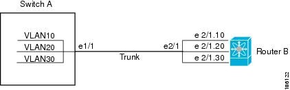
One use of subinterfaces is to provide unique Layer 3 interfaces to each VLAN that is supported by the parent interface. In this scenario, the parent interface connects to a Layer 2 trunking port on another device. You configure a subinterface and associate the subinterface to a VLAN ID using 802.1Q trunking.
The following figure shows a trunking port from a switch that connects to router B on interface E 2/1. This interface contains three subinterfaces that are associated with each of the three VLANs that are carried by the trunking port.
VLAN Interfaces
A VLAN interface or a switch virtual interface (SVI) is a virtual routed interface that connects a VLAN on the device to the Layer 3 router engine on the same device. Only one VLAN interface can be associated with a VLAN, but you need to configure a VLAN interface for a VLAN only when you want to route between VLANs or to provide IP host connectivity to the device through a virtual routing and forwarding (VRF) instance that is not the management VRF. When you enable VLAN interface creation, Cisco NX-OS creates a VLAN interface for the default VLAN (VLAN 1) to permit remote switch administration.
You must enable the VLAN network interface feature before you can configure it. The system automatically takes a checkpoint prior to disabling the feature, and you can roll back to this checkpoint. For information about rollbacks and checkpoints, see the System Management Configuration Guide for your device.
 Note | You cannot delete the VLAN interface for VLAN 1. |
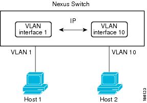
You can route across VLAN interfaces to provide Layer 3 inter-VLAN routing by configuring a VLAN interface for each VLAN that you want to route traffic to and assigning an IP address on the VLAN interface. For more information on IP addresses and IP routing, see the Unicast Routing Configuration Guide for your device.
The following figure shows two hosts connected to two VLANs on a device. You can configure VLAN interfaces for each VLAN that allows Host 1 to communicate with Host 2 using IP routing between the VLANs. VLAN 1 communicates at Layer 3 over VLAN interface 1and VLAN 10 communicates at Layer 3 over VLAN interface 10.
Loopback Interfaces
A loopback interface is a virtual interface with a single endpoint that is always up. Any packet that is transmitted over a loopback interface is immediately received by this interface. Loopback interfaces emulate a physical interface.
You can use loopback interfaces for performance analysis, testing, and local communications. Loopback interfaces can act as a termination address for routing protocol sessions. This loopback configuration allows routing protocol sessions to stay up even if some of the outbound interfaces are down.
Tunnel Interfaces
Cisco NX-OS supports tunnel interfaces as IP tunnels. IP tunnels can encapsulate a same- layer or higher layer protocol and transport the result over IP through a tunnel that is created between two routers.
Licensing Requirements for Layer 3 Interfaces
This feature does not require a license. Any feature not included in a license package is bundled with the Cisco NX-OS system images and is provided at no extra charge to you. For a complete explanation of the Cisco NX-OS licensing scheme, see the Cisco NX-OS Licensing Guide.
Guidelines and Limitations for Layer 3 Interfaces
-
If you change a Layer 3 interface to a Layer 2 interface, Cisco NX-OS shuts down the interface, reenables the interface, and removes all configuration specific to Layer 3.
-
If you change a Layer 2 interface to a Layer 3 interface, Cisco NX-OS shuts down the interface, reenables the interface, and deletes all configuration specific to Layer 2.
-
Cisco Nexus 3016 will punt multicast Layer 2 traffic to the CPU if the Layer 3 MTU is not the same for all Layer 3 interfaces, and if the MTU QoS was changed to jumbo. All Layer 3 interfaces must have the same Layer 3 MTU to avoid this issue.
Default Settings for Layer 3 Interfaces
The default setting for the Layer 3 Admin state is Shut.
SVI Autostate Disable
The SVI Autostate Disable feature enables the Switch Virtual Interface (SVI) to be in the “up” state even if no interface is in the “up” state in the corresponding VLAN.
An SVI is also a virtual routed interface that connects a VLAN on the device to the Layer 3 router engine on the same device. The ports in a VLAN determine the operational state of the corresponding SVI. An SVI interface on a VLAN comes “up” when at least one port in the corresponding VLAN is in the Spanning Tree Protocol (STP) forwarding state. Similarly, the SVI interface goes “down” when the last STP forwarding port goes down or to any other state. This characteristic of SVI is called 'Autostate'.
You can create SVIs to define Layer 2 or Layer 3 boundaries on VLANs, or use the SVI interface to manage devices. In the second scenario, the SVI Autostate Disable feature ensures that the SVI interface is in the “up” state even if no interface is in the “up” state in the corresponding VLAN.
DHCP Client Discovery
Cisco NX-OS Release 6.0(2)U3(1) introduced DHCP client discovery on SVIs. Cisco NX-OS Release 6.0(2)U4(1) adds DHCP client discovery support for IPv6 addresses and physical Ethernet and management interfaces. You can configure the IP address of a DHCP client by using the ip address dhcp or ipv6 address dhcp command. These commands sends a request from the DHCP client to the DHCP server soliciting an IPv4 or IPv6 address from the DHCP server. The DHCP client on the Cisco Nexus switch identifies itself to the DHCP server. The DHCP server uses this identifier to send the IP address back to the DHCP client.
When a DHCP client is configured on the SVI with the DHCP server sending router and DNS options, the ip route 0.0.0.0/0 router-ip and ip name-server dns-ip commands are configured on the switch automatically.
If the switch is reloaded and, at the same time, the router and DNS options are disabled on the server side, after the switch comes up, a new IP address is assigned to the SVI. However, the stale ip route command and ip name-server command will still exist in the switch configuration. You must manually remove these commands from the configuration.
Limitations for Using DHCP Client Discovery on Interfaces
The following are the limitations for using DHCP client discovery on interfaces:
-
This feature is supported only on physical Ethernet interfaces, management interfaces, and SVIs.
-
Starting with Cisco NX-OS Release 6.0(2)U4(1), this feature is supported on non-default virtual routing and forwarding (VRF) instances as well.
-
The DNS server and default router option-related configurations are saved in the startup configuration when you enter the copy running-config startup-config command. When you reload the switch, if this configuration is not applicable, you might have to remove it.
-
You can configure a maximum of six DNS servers on the switch, which is a switch limitation. This maximum number includes the DNS servers configured by the DHCP client and the DNS servers configured manually.
-
If the number of DNS servers configured on the switch is more than six, and if you get a DHCP offer for an SVI with DNS option set, the IP address is not assigned to the SVI.
MAC-Embedded IPv6 Address
Beginning with Cisco NX-OS Release 6.0(2)U4(1), BGP allows an IPv4 prefix to be carried over an IPv6 next-hop. The IPv6 next-hop is leveraged to remove neighbor discovery (ND) related traffic from the network. To do this, the MAC address is embedded in the IPv6 address. Such an address is called a MAC Embedded IPv6 (MEv6) address. The router extracts the MAC address directly from the MEv6 address instead of going through ND. Local interface and next-hop MAC addresses are extracted from the IPv6 addresses.
On MEv6-enabled IPv6 interfaces, the same MEv6 extracted MAC address is used for IPv4 traffic as well. MEv6 is supported on all Layer 3 capable interfaces except SVIs.
When MEv6 is enabled on an interface, ping6 to the IPv6 link local address, OSPFv3, and BFDv6 are not supported on that interface.
Configuring Layer 3 Interfaces
Configuring a Routed Interface
This example shows how to configure an IPv4-routed Layer 3 interface:
switch# configure terminal
switch(config)# interface ethernet 2/1
switch(config-if)# no switchport
switch(config-if)# ip address 192.0.2.1/8
switch(config-if)# copy running-config startup-config
Configuring a Subinterface
| Command or Action | Purpose | |
|---|---|---|
| Step 1 | switch(config-if)# copy running-config startup-config | (Optional)
Saves the change persistently through reboots and restarts by copying the running configuration to the startup configuration. |
| Step 2 | switch(config)# interface ethernet slot/port.number | Enters interface configuration mode. The range for the slot is from 1 to 255. The range for the port is from 1 to 128. |
| Step 3 | switch(config-if)# [ip | ipv6] address ip-address/length | Configures an IP address for this interface. |
| Step 4 | switch(config-if)# encapsulation dot1Q vlan-id | Configures IEEE 802.1Q VLAN encapsulation on the subinterface. The range for the vlan-id is from 2 to 4093. |
| Step 5 | switch(config-if)# show interfaces | (Optional) Displays the Layer 3 interface statistics. |
| Step 6 | switch(config-if)# copy running-config startup-config | (Optional)
Saves the change persistently through reboots and restarts by copying the running configuration to the startup configuration. |
This example shows how to create a subinterface:
switch# configure terminal
switch(config)# interface ethernet 2/1
switch(config-if)# ip address 192.0.2.1/8
switch(config-if)# encapsulation dot1Q 33
switch(config-if)# copy running-config startup-config
Configuring the Bandwidth on an Interface
You can configure the bandwidth for a routed interface, port channel, or subinterface.
| Command or Action | Purpose | |
|---|---|---|
| Step 1 | switch# configure terminal |
Enters global configuration mode. |
| Step 2 | switch(config)# interface ethernet slot/port | Enters interface configuration mode. The range for the slot is from 1 to 255. The range for the port is from 1 to 128. |
| Step 3 | switch(conifg-if)# bandwidth [value | inherit [value]] | Configures the bandwidth parameter for a routed interface, port channel, or subinterface, as follows: |
| Step 4 | switch(config-if)# copy running-config startup-config | (Optional)
Saves the change persistently through reboots and restarts by copying the running configuration to the startup configuration. |
This example shows how to configure Ethernet interface 2/1 with a bandwidth value of 80000:
switch# configure terminal
switch(config)# interface ethernet 2/1
switch(config-if)# bandwidth 80000
switch(config-if)# copy running-config startup-config
Configuring a VLAN Interface
| Command or Action | Purpose | |
|---|---|---|
| Step 1 | switch# configure terminal |
Enters global configuration mode. |
| Step 2 | switch(config)# feature interface-vlan | Enables VLAN interface mode. |
| Step 3 | switch(config)# interface vlan number | Creates a VLAN interface. The number range is from 1 to 4094. |
| Step 4 | switch(config-if)# [ip | ipv6 ] address ip-address/length | Configures an IP address for this interface. |
| Step 5 | switch(config-if)# no shutdown | Brings the interface up administratively. |
| Step 6 | switch(config-if)# show interface vlan number | (Optional) Displays the VLAN interface statistics. The number range is from 1 to 4094. |
| Step 7 | switch(config-if)# copy running-config startup-config | (Optional)
Saves the change persistently through reboots and restarts by copying the running configuration to the startup configuration. |
This example shows how to create a VLAN interface:
switch# configure terminal
switch(config)# feature interface-vlan
switch(config)# interface vlan 10
switch(config-if)# ip address 192.0.2.1/8
switch(config-if)# copy running-config startup-config
Configuring a Loopback Interface
Ensure that the IP address of the loopback interface is unique across all routers on the network.
| Command or Action | Purpose | |
|---|---|---|
| Step 1 | switch# configure terminal | Enters global configuration mode. |
| Step 2 | switch(config)# interface loopback instance | Creates a loopback interface. The instance range is from 0 to 1023. |
| Step 3 | switch(config-if)# [ip | ipv6 ] address ip-address/length | Configures an IP address for this interface. |
| Step 4 | switch(config-if)# show interface loopback instance | (Optional) Displays the loopback interface statistics. The instance range is from 0 to 1023. |
| Step 5 | switch(config-if)# copy running-config startup-config | (Optional)
Saves the change persistently through reboots and restarts by copying the running configuration to the startup configuration. |
This example shows how to create a loopback interface:
switch# configure terminal
switch(config)# interface loopback 0
switch(config-if)# ip address 192.0.2.100/8
switch(config-if)# copy running-config startup-config
Assigning an Interface to a VRF
Assign the IP address for a tunnel interface after you have configured the interface for a VRF.
| Command or Action | Purpose | |
|---|---|---|
| Step 1 | switch# configure terminal |
Enters global configuration mode. |
| Step 2 | switch(config)# interface interface-typenumber |
Enters interface configuration mode. |
| Step 3 | switch(conifg-if)#vrf member vrf-name |
Adds this interface to a VRF. |
| Step 4 | switch(config-if)# [ip | ipv6]ip-address/length |
Configures an IP address for this interface. You must do this step after you assign this interface to a VRF. |
| Step 5 | switch(config-if)# show vrf [vrf-name] interface interface-type number | (Optional)
Displays VRF information. |
| Step 6 | switch(config-if)# show interfaces | (Optional)
Displays the Layer 3 interface statistics. |
| Step 7 | switch(config-if)# copy running-config startup-config | (Optional)
Saves the change persistently through reboots and restarts by copying the running configuration to the startup configuration. |
This example shows how to add a Layer 3 interface to the VRF:
switch# configure terminal
switch(config)# interface loopback 0
switch(config-if)# vrf member RemoteOfficeVRF
switch(config-if)# ip address 209.0.2.1/16
switch(config-if)# copy running-config startup-config
Configuring an Interface MAC Address
You can configure a static MAC address on SVI, Layer 3 interfaces, port channels, Layer 3 subinterfaces, and tunnel interfaces. You can also configure static MAC addresses on a range of ports and port channels. However, all ports must be in Layer 3. Even if one port in the range of ports is in Layer 2, the command is rejected and an error message appears.
| Command or Action | Purpose | |
|---|---|---|
| Step 1 | switch# configure terminal |
Enters global configuration mode. |
| Step 2 | switch(config)# interface ethernet slot/port | Enters interface configuration mode. |
| Step 3 | switch(config-if)# [no] mac-address static router MAC address |
|
| Step 4 | switch(config-if)# show interface ethernet slot/port | (Optional) Displays all information for the interface. |
This example shows how to configure an interface MAC address:
switch# configure terminal
switch(config)# interface ethernet 3/3
switch(config-if)# mac-address aaaa.bbbb.dddd
switch(config-if)# show interface ethernet 3/3
switch(config-if)#
Configuring a MAC-Embedded IPv6 Address
| Command or Action | Purpose | |||
|---|---|---|---|---|
| Step 1 | switch# configure terminal |
Enters global configuration mode. | ||
| Step 2 | switch(config)# interface type slot/port |
Enters the interface configuration mode for the specified interface. | ||
| Step 3 | switch(config-if)# no switchport |
Configures the interface as a Layer 3 interface and deletes any configuration specific to Layer 2 on this interface.
| ||
| Step 4 | switch(config-if)# mac-address ipv6-extract |
Extracts the MAC address embedded in the IPv6 address configured on the interface.
| ||
| Step 5 | switch(config-if)# ipv6 address ip-address/length |
Configures an IPv6 address for this interface. | ||
| Step 6 | switch(config-if)# ipv6 nd mac-extract [exclude nud-phase] |
Extracts the next-hop MAC address embedded in a next-hop IPv6 address. The exclude nud-phase option blocks packets during the ND phase only. When the exclude nud-phase option is not specified, packets are blocked during both ND and Neighbor Unreachability Detection (NUD) phases. | ||
| Step 7 | switch(config)# show ipv6 icmp interface type slot/port | (Optional)
Displays IPv6 Internet Control Message Protocol version 6 (ICMPv6) interface information. |
This example shows how to configure a MAC-embedded IPv6 address with ND mac-extract enabled:
switch# configure terminal
Enter configuration commands, one per line.  End with CNTL/Z.
switch(config)# interface ethernet 1/3
switch(config-if)# no switchport
switch(config-if)# mac-address ipv6-extract
switch(config-if)# ipv6 address 2002:1::10/64
switch(config-if)# ipv6 nd mac-extract
switch(config-if)# show ipv6 icmp interface ethernet 1/3
ICMPv6 Interfaces for VRF "default"
Ethernet1/3, Interface status: protocol-up/link-up/admin-up
  IPv6 address: 2002:1::10
  IPv6 subnet:  2002:1::/64
  IPv6 interface DAD state:  VALID
  ND mac-extract : Enabled
  ICMPv6 active timers:
      Last Neighbor-Solicitation sent: 00:01:39
      Last Neighbor-Advertisement sent: 00:01:40
      Last Router-Advertisement sent: 00:01:41
      Next Router-Advertisement sent in: 00:03:34
  Router-Advertisement parameters:
      Periodic interval: 200 to 600 seconds
      Send "Managed Address Configuration" flag: false
      Send "Other Stateful Configuration" flag: false
      Send "Current Hop Limit" field: 64
      Send "MTU" option value: 1500
      Send "Router Lifetime" field: 1800 secs
      Send "Reachable Time" field: 0 ms
      Send "Retrans Timer" field: 0 ms
      Suppress RA: Disabled
      Suppress MTU in RA: Disabled
  Neighbor-Solicitation parameters:
      NS retransmit interval: 1000 ms
  ICMPv6 error message parameters:
      Send redirects: true
      Send unreachables: false
  ICMPv6-nd Statisitcs (sent/received):
      RAs: 3/0, RSs: 0/0, NAs: 2/0, NSs: 7/0, RDs: 0/0
      Interface statistics last reset: never
switch(config)#
This example shows how to configure a MAC-embedded IPv6 address with ND mac-extract (excluding NUD phase) enabled:
switch# configure terminal
Enter configuration commands, one per line.  End with CNTL/Z.
switch(config)# interface ethernet 1/5
switch(config-if)# no switchport
switch(config-if)# mac-address ipv6-extract
switch(config-if)# ipv6 address 2002:2::10/64
switch(config-if)# ipv6 nd mac-extract exclude nud-phase
switch(config-if)# show ipv6 icmp interface ethernet 1/5
ICMPv6 Interfaces for VRF "default"
Ethernet1/5, Interface status: protocol-up/link-up/admin-up
  IPv6 address: 2002:2::10
  IPv6 subnet:  2002:2::/64
  IPv6 interface DAD state:  VALID
  ND mac-extract : Enabled (Excluding NUD Phase)
  ICMPv6 active timers:
      Last Neighbor-Solicitation sent: 00:06:45
      Last Neighbor-Advertisement sent: 00:06:46
      Last Router-Advertisement sent: 00:02:18
      Next Router-Advertisement sent in: 00:02:24
  Router-Advertisement parameters:
      Periodic interval: 200 to 600 seconds
      Send "Managed Address Configuration" flag: false
      Send "Other Stateful Configuration" flag: false
      Send "Current Hop Limit" field: 64
      Send "MTU" option value: 1500
      Send "Router Lifetime" field: 1800 secs
      Send "Reachable Time" field: 0 ms
      Send "Retrans Timer" field: 0 ms
      Suppress RA: Disabled
      Suppress MTU in RA: Disabled
  Neighbor-Solicitation parameters:
      NS retransmit interval: 1000 ms
  ICMPv6 error message parameters:
      Send redirects: true
      Send unreachables: false
  ICMPv6-nd Statisitcs (sent/received):
      RAs: 6/0, RSs: 0/0, NAs: 2/0, NSs: 7/0, RDs: 0/0
      Interface statistics last reset: never
switch(config-if)#
Configuring SVI Autostate Disable
You can configure a SVI to remain active even if no interfaces are up in the corresponding VLAN. This enhancement is called Autostate Disable.
| Command or Action | Purpose | |
|---|---|---|
| Step 1 | switch# configure terminal |
Enters global configuration mode. |
| Step 2 | switch(config)# system default interface-vlan autostate | Reenables the system default autostate behavior on Switching Virtual Interface (SVI) in a VLAN. Use the no form of the command to disable the autostate behavior on SVI. |
| Step 3 | switch(config)# feature interface-vlan | Enables the creation of VLAN interfaces SVI. |
| Step 4 | switch(config)# interface vlan vlan id | Disables the VLAN interface and enters interface configuration mode. |
| Step 5 | (config-if)# [no] autostate | Disables the default autostate behavior of SVIs on the VLAN interface. |
| Step 6 | (config-if)# end | Returns to privileged EXEC mode. |
| Step 7 | show running-config interface vlan
vlan id
| (Optional) Displays the running configuration for a specific port channel. |
This example shows how to configure the SVI Autostate Disable feature:
switch# configure terminal
switch(config)# system default interface-vlan autostate
switch(config)# feature interface-vlan
switch(config)# interface vlan 2
switch(config-if)# no autostate
switch(config-if)# end
Configuring a DHCP Client on an Interface
You can configure the IP address of a DHCP client on an SVI, a management interface, or a physical Ethernet interface.
| Command or Action | Purpose | |
|---|---|---|
| Step 1 | switch# configure terminal |
Enters global configuration mode. |
| Step 2 | switch(config)# interface ethernet type slot/port | mgmt mgmt-interface-number | vlan vlan id |
Creates a physical Ethernet interface, a management interface, or a VLAN interface. The range of vlan id is from 1 to 4094. |
| Step 3 | switch(config-if)# [no] ip | ipv6 address dhcp |
Requests the DHCP server for an IPv4 or IPv6 address. The no form of this command removes any address that was acquired. |
| Step 4 | switch(config)# copy running-config startup-config | (Optional)
Saves the change persistently through reboots and restarts by copying the running configuration to the startup configuration. |
This example shows how to configure the IP address of a DHCP client on an SVI:
switch# configure terminal
switch(config)# interface vlan 15
switch(config-if)# ip address dhcp
This example shows how to configure an IPv6 address of a DHCP client on a management interface:
switch# configure terminal
switch(config)# interface mgmt 0
switch(config-if)# ipv6 address dhcp
Verifying the Layer 3 Interfaces Configuration
Use one of the following commands to verify the configuration:
|
Command |
Purpose |
|---|---|
|
show interface ethernet slot/port |
Displays the Layer 3 interface configuration, status, and counters (including the 5-minute exponentially decayed moving average of inbound and outbound packet and byte rates). |
|
show interface ethernet slot/port brief |
Displays the Layer 3 interface operational status. |
|
show interface ethernet slot/port capabilities |
Displays the Layer 3 interface capabilities, including port type, speed, and duplex. |
|
show interface ethernet slot/port description |
Displays the Layer 3 interface description. |
|
show interface ethernet slot/port status |
Displays the Layer 3 interface administrative status, port mode, speed, and duplex. |
|
show interface ethernet slot/port.number |
Displays the subinterface configuration, status, and counters (including the f-minute exponentially decayed moving average of inbound and outbound packet and byte rates). |
|
show interface port-channel channel-id.number |
Displays the port-channel subinterface configuration, status, and counters (including the 5-minute exponentially decayed moving average of inbound and outbound packet and byte rates). |
|
show interface loopback number |
Displays the loopback interface configuration, status, and counters. |
|
show interface loopback number brief |
Displays the loopback interface operational status. |
|
show interface loopback number description |
Displays the loopback interface description. |
|
show interface loopback number status |
Displays the loopback interface administrative status and protocol status. |
|
show interface vlan number |
Displays the VLAN interface configuration, status, and counters. |
|
show interface vlan number brief |
Displays the VLAN interface operational status. |
|
show interface vlan number description |
Displays the VLAN interface description. |
|
show interface vlan number private-vlan mapping |
Displays the VLAN interface private VLAN information. |
|
show interface vlan number status |
Displays the VLAN interface administrative status and protocol status. |
Triggering the Layer 3 Interface Consistency Checker
You can manually trigger the Layer 3 interface consistency checker to compare the hardware and software configuration of all physical interfaces in a module and display the results. To manually trigger the Layer 3 Interface consistency checker and display the results, use the following command in any mode:
| Command or Action | Purpose |
|---|
This example shows how to trigger the Layer 3 interface consistency check and display its results:
switch# show consistency-checker l3-interface module 1
L3 LIF Checks: L3 Vlan, CML Flags, IPv4 Enable
Consistency Check: PASSED
No inconsistencies found for:
   Ethernet1/17
   Ethernet1/49
   Ethernet1/50
Monitoring Layer 3 Interfaces
Use one of the following commands to display statistics about the feature:
|
Command |
Purpose |
|---|---|
|
load-interval seconds | counter {1 | 2 | 3} seconds |
Sets three different sampling intervals to bit-rate and packet-rate statistics. The range is from 5 seconds to 300 seconds. |
|
show interface ethernet slot/port counters |
Displays the Layer 3 interface statistics (unicast, multicast, and broadcast). |
|
show interface ethernet slot/port counters brief load-interval-id |
Displays the Layer 3 interface input and output counters. The load interval ID specifies a single load interval ID to display the input and output rates. The load interval ID ranges between 1 and 3. |
|
show interface ethernet slot/port counters detailed [all] |
Displays the Layer 3 interface statistics. You can optionally include all 32-bit and 64-bit packet and byte counters (including errors). |
|
show interface ethernet slot/port counters error |
Displays the Layer 3 interface input and output errors. |
|
show interface ethernet slot/port counters snmp |
Displays the Layer 3 interface counters reported by SNMP MIBs. You cannot clear these counters. |
|
show interface ethernet slot/port.number counters |
Displays the subinterface statistics (unicast, multicast, and broadcast). |
|
show interface port-channel channel-id.number counters |
Displays the port-channel subinterface statistics (unicast, multicast, and broadcast). |
|
show interface loopback number counters |
Displays the loopback interface input and output counters (unicast, multicast, and broadcast). |
|
show interface loopback number counters detailed [all] |
Displays the loopback interface statistics. You can optionally include all 32-bit and 64-bit packet and byte counters (including errors). |
|
show interface loopback number counters errors |
Displays the loopback interface input and output errors. |
|
show interface vlan number counters |
Displays the VLAN interface input and output counters (unicast, multicast, and broadcast). |
|
show interface vlan number counters detailed [all] |
Displays the VLAN interface statistics. You can optionally include all Layer 3 packet and byte counters (unicast and multicast). |
|
show interface vlan counters snmp |
Displays the VLAN interface counters reported by SNMP MIBs. You cannot clear these counters. |
Configuration Examples for Layer 3 Interfaces
switch# configuration terminal
switch(config)# interface ethernet 2/1.10
switch(config-if)# description Layer 3 for VLAN 10
switch(config-if)# encapsulation dot1q 10
switch(config-if)# ip address 192.0.2.1/8
switch(config-if)# copy running-config startup-config
switch# configuration terminal
switch(config)# interface vlan 100
switch(config-if)# no switchport

switch(config-if)# ipv6 address 33:0DB::2/8
switch(config-if)# copy running-config startup-config
This example shows how to configure Switching Virtual Interface (SVI) Autostate Disable:
switch# configure terminal
switch(config)# system default interface-vlan autostate
switch(config)# feature interface-vlan
switch(config)# interface vlan 2
switch(config-if)# no autostate
switch(config-if)# end
switch# show running-config interface vlan 2
switch# configuration terminal
switch(config)# interface loopback 3
switch(config-if)# no switchport
switch(config-if)# ip address 192.0.2.2/32
switch(config-if)# copy running-config startup-config
switch# configure terminal
switch(config)# interface ethernet 1/3
switch(config-if)# load-interval counter 1 5
switch(config-if)# load-interval counter 2 135
switch(config-if)# load-interval counter 3 225
switch(config-if)#
Related Documents for Layer 3 Interfaces
| Related Topics | Document Title |
|---|---|
Command syntax |
Cisco Nexus 3000 Series Command Reference |
IP |
“Configuring IP” chapter in the Cisco Nexus 3000 Series NX-OS Unicast Routing Configuration Guide |
VLAN |
“Configuring VLANs” chapter in the Cisco Nexus 3000 Series NX-OS Layer 2 Switching Configuration Guide |
MIBs for Layer 3 Interfaces
| MIB | MIB Link |
|---|---|
CISCO-IF-EXTENSION-MIB |
To locate and download MIBs, go to the following URL: http://www.cisco.com/public/sw-center/netmgmt/cmtk/mibs.shtml |
ETHERLIKE-MIB |
Standards for Layer 3 Interfaces
No new or modified standards are supported by this feature, and support for existing standards has not been modified by this feature.
Feature History for Layer 3 Interfaces
Feature Name |
Release |
Feature Information |
|---|---|---|
5.0(3)U3(1) |
The show interface vlan vlan-id counters command has been enhanced to correctly show input and output packet counts. |
 Feedback