Installing Cisco Nexus 1000V
This chapter describes the prerequisites, guidelines and limitations, and the process to install Cisco Nexus 1000V.
For information about your software and platform compatibility, see Cisco Nexus 1000V and Microsoft Hyper-V Compatibility Information.
Prerequisites for Installing the VSM Software
Before You Begin
Ensure that you have installed and configured the following components on the target setup:
- Windows Active Directory service.
- Microsoft System Center Virtual Machine Manager (SCVMM) 2016.
- Windows Server 2016 hosts.
For more information, see http://support.microsoft.com/kb/3014795/en-us.
Guidelines and Limitations
It is your responsibility to monitor and install all the relevant patches from Microsoft on the Windows hosts.
System Requirements
This section describes the hardware and software requirements.
Hardware Requirements
The hardware must meet the requirements set by Microsoft to run the Hyper-V role. The Cisco Nexus 1000V Virtual Supervisor Module (VSM) requires VMs with the following configuration:
- 4 GB minimum of hard disk space
- 4 GB minimum of RAM
- As a best practice, we recommend that you have four network adapters (network interface cards—NICs) on the host where Microsoft Hyper-V is installed. You can have various combinations depending on the hardware that you have. For example, you can have one NIC with four ports or four NICs with one port each.
Software Requirements
To install and bring up a Cisco Nexus 1000V, you need the following server setup:
To configure the VSM, you need the following information:
- VSM IP address
- VSM domain ID (1–1023)—This ID is used for high availability (HA).
- Layer 3 connectivity between a VSM and the hosts that run a VEM is required.
–![]() Layer2 mode is not supported.
Layer2 mode is not supported.
–![]() Layer3 UDP port number 4785.
Layer3 UDP port number 4785.
–![]() Communication between the VSM and VEM occurs over UDP port number 4785 that uses the Cisco Nexus Control Protocol (CNCP).
Communication between the VSM and VEM occurs over UDP port number 4785 that uses the Cisco Nexus Control Protocol (CNCP).
VSM NIC Ordering
The VSM creates interfaces in an ascending MAC address order of the virtual NIC offered by Microsoft Hyper-V. Currently, Microsoft Hyper V provides no guarantees that this order is the same as displayed at the VSM VM Settings panel. The VSM always uses its first interface as control0 and its second interface as mgmt0. The network profiles for these two interfaces might need different VLANs. Therefore, you should verify that the interfaces are selected by the VSM in the same order that are displayed in the Settings panel.
Enter the following command on the VSM to verify the order of the management and control MAC addresses:
If the order is not the same, use the following commands to specify the preferred MAC-to-control0/mgmt0 interface mappings:
These commands require that you enter the copy running-config startup-config command afterwards to make the change persistent and effective after the next VSM reload.
If any of the preferred MACs are not available at VSM bootup, the driver picks another interface instead (following MAC ascending order). The system logs an error with a syslog as follows:
Basic Topology
Figure 1-1 displays the basic Hyper-V topology on a Cisco Nexus 1000V VEM.
Figure 1-1 Basic Topology for the Cisco Nexus 1000V
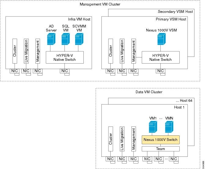

Note![]() The management NIC is actually on the Microsoft switch. The management VM cluster is for infra VMs. The data VM cluster is for workload VMs. The minimum topology is three servers with four NICs each.
The management NIC is actually on the Microsoft switch. The management VM cluster is for infra VMs. The data VM cluster is for workload VMs. The minimum topology is three servers with four NICs each.
Figure 1-1 displays the Cisco Nexus 1000V deployment on two servers with the following network configuration:
- Management NIC—This network adapter is connected to an external network for the host OS connectivity.
- Microsoft virtual switch—The Microsoft virtual switch has one physical network adapter for the VSM connectivity.
- Two physical network adapters—These adapters are connected to the Cisco Nexus 1000V logical switch instance of the Hyper-V host.
Installation Workflow
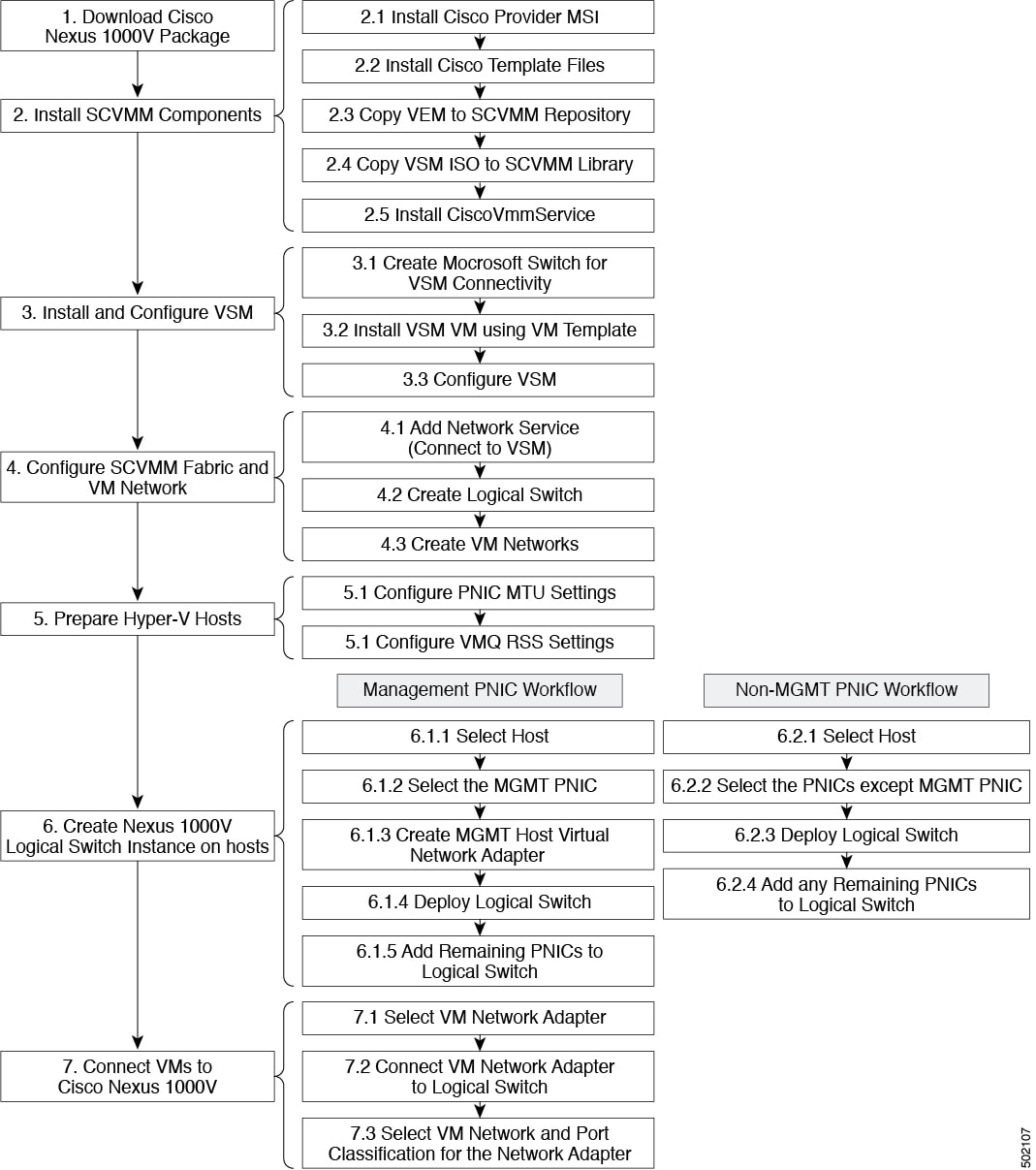
Figure 1-2 displays the Cisco Nexus 1000V installation process on Microsoft SCVMM.
Figure 1-2 Cisco Nexus 1000V Installation Workflow
Installing the VSM Software
To install the VSM software, perform the following steps:
1.![]() Downloading the Cisco Nexus 1000V Package
Downloading the Cisco Nexus 1000V Package
3.![]() Installing the VSM Certificate
Installing the VSM Certificate
4.![]() Preparing the Microsoft Hyper-V Hosts (Optional)
Preparing the Microsoft Hyper-V Hosts (Optional)
5.![]() Adding Hosts to a Logical Switch
Adding Hosts to a Logical Switch
6.![]() Installation of CiscoVmmService
Installation of CiscoVmmService
8.![]() Uninstallation of CiscoVmmService
Uninstallation of CiscoVmmService
9.![]() Connecting the VM Network Adapter to the Logical Switch
Connecting the VM Network Adapter to the Logical Switch
Downloading the Cisco Nexus 1000V Package
The Cisco Nexus 1000V for Microsoft Hyper-V package (a zip file) is available at the download URL location provided with the software.
To download the Cisco Nexus 1000V package, download the Cisco Nexus 1000V package for the HyperV platform. This package contains the following files:
- VSM ISO (Nexus1000V.5.2.1.SM3.2.1\VSM\install\Nexus-1000V.5.2.1.SM3.2.1.iso)
- VEM MSI package (Nexus1000V.5.2.1.SM3.2.1\VEM\Nexus1000V-VEM-5.2.1.SM3.2.1.msi)
- Cisco VSEM Provider MSI package (Nexus1000V.5.2.1.SM3.2.1\VMM\Nexus1000V-NetworkServiceProvider-5.2.1.SM3.2.1.msi)
- Kickstart file (Nexus1000V.5.2.1.SM3.2.1\VSM\Upgrade\Nexus-1000V-kickstart.5.2.1.SM3.2.1.bin)
- System file (Nexus1000V.5.2.1.SM3.2.1\VSM\Upgrade\Nexus-1000V.5.2.1.SM3.2.1.bin)
- PNSC-PA (Nexus1000V.5.2.1.SM3.2.1\PNSC-PA\vsmhv-pa.3.2.1e.bin)
- WSUS scripts (Nexus1000V.5.2.1.SM3.2.1\WSUS\)
Configuring SCVMM and VSM
This section describes how to install the Cisco Nexus 1000V for Microsoft Hyper-V VSM software and includes the following topics:
Installing SCVMM Components
To install the SCVMM components, perform the following steps:
Step 1![]() Install the Cisco Provider MSI.
Install the Cisco Provider MSI.
a.![]() Install the Nexus1000V-NetworkServiceProvider-5.2.1.SM3.2.1.0.msi from the Cisco Nexus1000V zip location on the SCVMM server in order to establish communication between SCVMM and the Cisco Nexus1000V VSM.
Install the Nexus1000V-NetworkServiceProvider-5.2.1.SM3.2.1.0.msi from the Cisco Nexus1000V zip location on the SCVMM server in order to establish communication between SCVMM and the Cisco Nexus1000V VSM.
Note![]() The MSI installation restarts the SCVMM service.
The MSI installation restarts the SCVMM service.
b.![]() Verify that the Cisco Provider is installed properly:
Verify that the Cisco Provider is installed properly:
- Open the SCVMM console.
- Navigate to the Settings Pane.
- Click Configuration Providers.
- Verify that the Cisco Nexus 1000V extension is displayed.
Step 2![]() Install the Cisco VSM template files.
Install the Cisco VSM template files.
After downloading the Cisco Nexus 1000V for Microsoft Hyper-V package, complete the following steps to install the VSM template:
- On the SCVMM server, open the PowerShell console from the SCVMM console.
- Run the script Register-Nexus1000VVSMTemplate.ps1 from the following location: %ProgramFiles%\Cisco\Nexus1000V\V2\Nexus1000V-VSMTemplate.
This script imports the Cisco VSM template in the SCVMM library.
–![]() Navigate to the Templates tab.
Navigate to the Templates tab.
–![]() Choose Templates. On the right pane, the Nexus 1000V-VSM-Template is listed.
Choose Templates. On the right pane, the Nexus 1000V-VSM-Template is listed.
Step 3![]() Copy the VEM to the SCVMM repository.
Copy the VEM to the SCVMM repository.
The VEM is an MSI file that needs to be placed in the following location on the SCVMM server: %ALLUSERSPROFILE%\Switch Extension Drivers. For example, C:\ProgramData\Switch Extension Drivers. SCVMM uses the MSI file during Add host operation.

Step 4![]() Copy the VSM ISO file. For example, copy Nexus-1000V.5.2.1.SM3.2.1.iso to the SCVMM library in the following location on SCVMM server: \\VMName\MSSCVMMLibrary. After copying the ISO file, make sure to refresh the SCVMM library so that SCVMM detects the copied ISO.
Copy the VSM ISO file. For example, copy Nexus-1000V.5.2.1.SM3.2.1.iso to the SCVMM library in the following location on SCVMM server: \\VMName\MSSCVMMLibrary. After copying the ISO file, make sure to refresh the SCVMM library so that SCVMM detects the copied ISO.
Step 5![]() Install CiscoVmmService which runs as a Windows service.
Install CiscoVmmService which runs as a Windows service.
The MSI file Nexus1000V-NetworkServiceProvider-5.2.1.SM3.2.1.0.msi also includes CiscoVmmService which is required for the automatic refresh of the network service and remediate at SCVMM. The files are located at the %ProgramFiles%\Cisco\Nexus1000V\V2\CiscoVmmService\ directory.
For more information, see Installation of CiscoVmmService.
Installing and Configuring the VSM Workflow
To install and configure the VSM workflow, use an existing Microsoft Switch with external connectivity or create a new one, for the VSM connectivity.
Installing the VSM using a VM Template
To install the VSM using a VM template, perform the following steps:
Step 1![]() From the left navigation pane in the SCVMM user interface, click the VMs and Services icon and from the top menu bar, choose Create Virtual Machine. The Create Virtual Machine wizard opens.
From the left navigation pane in the SCVMM user interface, click the VMs and Services icon and from the top menu bar, choose Create Virtual Machine. The Create Virtual Machine wizard opens.
Step 2![]() In the Select Source panel, choose the Use an existing virtual machine, VM template, or virtual hard disk option and click Browse.
In the Select Source panel, choose the Use an existing virtual machine, VM template, or virtual hard disk option and click Browse.
Step 3![]() Choose the Nexus1000V_VSM_Template file listed under the Type: VM Template header.
Choose the Nexus1000V_VSM_Template file listed under the Type: VM Template header.
Step 4![]() Click OK and click Next.
Click OK and click Next.
Step 5![]() In the Specify Virtual Machine Identity panel, enter the name of the virtual machine and click Next.
In the Specify Virtual Machine Identity panel, enter the name of the virtual machine and click Next.
Step 6![]() In the Configure Hardware panel, configure the hardware settings for the virtual machine. If you are using a template, most of the settings have already been configured (For example, the hard drive is set to 4 GB and there are three network adapters). The only item that you have to manually configure is the ISO image.
In the Configure Hardware panel, configure the hardware settings for the virtual machine. If you are using a template, most of the settings have already been configured (For example, the hard drive is set to 4 GB and there are three network adapters). The only item that you have to manually configure is the ISO image.
Step 7![]() Click Virtual DVD drive below the Bus Configuration header in the center pane.
Click Virtual DVD drive below the Bus Configuration header in the center pane.
Step 8![]() Click Existing ISO image file and click Browse.
Click Existing ISO image file and click Browse.
Step 9![]() Choose the ISO image from the SCVMM library, click Nework Adapter, choose the dynamic option for the MAC-address assignment.
Choose the ISO image from the SCVMM library, click Nework Adapter, choose the dynamic option for the MAC-address assignment.
Step 10![]() Click OK and then click Next.
Click OK and then click Next.
Step 11![]() In the Select Destination panel, keep the default settings of Place the virtual machine on a host; Destination: All Hosts and click Next.
In the Select Destination panel, keep the default settings of Place the virtual machine on a host; Destination: All Hosts and click Next.
Step 12![]() After the host is displayed in the Select Host panel, chose it, and click Next.
After the host is displayed in the Select Host panel, chose it, and click Next.
Step 13![]() In the Configure Settings panel, review the settings and click Next.
In the Configure Settings panel, review the settings and click Next.
Step 14![]() In the Select Networks panel, choose the virtual switches that are used for the virtual machine. For each network adapter, select the type of the virtual switch. For example, choose Standard Switch or Logical Switch and click Next.
In the Select Networks panel, choose the virtual switches that are used for the virtual machine. For each network adapter, select the type of the virtual switch. For example, choose Standard Switch or Logical Switch and click Next.
Step 15![]() In the Add Properties panel, under the Automatic Actions choose the following options:
In the Add Properties panel, under the Automatic Actions choose the following options:
Step 16![]() In the Confirm the Settings panel in the final Summary window, review and confirm the settings.
In the Confirm the Settings panel in the final Summary window, review and confirm the settings.
Step 17![]() Click Create to begin the virtual machine creation. A progress bar is displayed in the Job Status column in the VM window.
Click Create to begin the virtual machine creation. A progress bar is displayed in the Job Status column in the VM window.
Step 18![]() After the virtual machine creation is complete, right-click the Name of the virtual machine in the SCVMM user interface and choose Power On.
After the virtual machine creation is complete, right-click the Name of the virtual machine in the SCVMM user interface and choose Power On.
Step 19![]() Right-click the Name of the virtual machine again, click Connect or View, and choose Connect via Console.
Right-click the Name of the virtual machine again, click Connect or View, and choose Connect via Console.
See Table 1-1 for more information about the Cisco Nexus 1000V ISO boot options.
Configuring the VSM
After installing VSM using a VM template, connect to a VM console and configure the VSM. We recommend that the VSM is deployed using the template provided by Cisco. After the deployment is complete, power on the VSM. The following basic inputs are required for the VSM configuration:
Note![]() Make sure that you eject the virtual ISO image from the CD ROM.
Make sure that you eject the virtual ISO image from the CD ROM.
Deploying the VSM
To deploy the VSM, perform the following steps:
Step 1![]() When the Virtual Machine Viewer window opens, the message “Do you want to format it? (y/n)” appears. Enter Y (yes).
When the Virtual Machine Viewer window opens, the message “Do you want to format it? (y/n)” appears. Enter Y (yes).
Step 2![]() At the command prompt, when the message “Perform r/w tests (takes very long time) on target disks? (y/n)” appears, enter Y (yes).
At the command prompt, when the message “Perform r/w tests (takes very long time) on target disks? (y/n)” appears, enter Y (yes).
Note![]() The default action is taken if you do not immediately respond to the message prompts.
The default action is taken if you do not immediately respond to the message prompts.
Step 3![]() After the software is copied and the CD-ROM drive is mounted, you are prompted to enter the System Administrator Account Setup. At the Enter the password for “admin”: prompt, enter the password. At the Confirm the password for “admin”: prompt, reenter the password.
After the software is copied and the CD-ROM drive is mounted, you are prompted to enter the System Administrator Account Setup. At the Enter the password for “admin”: prompt, enter the password. At the Confirm the password for “admin”: prompt, reenter the password.
Step 4![]() Enter the HA role at the prompt Enter HA role [standalone/primary/secondary].
Enter the HA role at the prompt Enter HA role [standalone/primary/secondary].
Note![]() We recommend that you create a VSM HA pair. Configure the first VM as the primary VSM and install the second VM as the secondary VSM.
We recommend that you create a VSM HA pair. Configure the first VM as the primary VSM and install the second VM as the secondary VSM.
If you set the HA role as secondary, the following question is displayed at the prompt: Setting HA role to secondary will cause a system reboot. Are you sure (yes/no)?: Enter Yes if you want to set the HA role to Secondary.
Step 5![]() At the prompt, enter the domain ID: Enter the domain ID[1-1023]; for example, 199. A domain ID is required for the VSMs to communicate with each other. While installing the secondary VSM, enter the same domain ID that was specified for the primary VSM.
At the prompt, enter the domain ID: Enter the domain ID[1-1023]; for example, 199. A domain ID is required for the VSMs to communicate with each other. While installing the secondary VSM, enter the same domain ID that was specified for the primary VSM.
Step 6![]() After step 5 for secondary VSM, the message is displayed: saving boot configuration and the system reloads.
After step 5 for secondary VSM, the message is displayed: saving boot configuration and the system reloads.
Step 7![]() At the prompt, the Basic System Configuration Dialog is displayed. Enter Yes at the prompt.
At the prompt, the Basic System Configuration Dialog is displayed. Enter Yes at the prompt.
Step 8![]() At the command prompt, the following message is displayed: Create another login account? [yes/no] (n). Select No to skip creating another login account.
At the command prompt, the following message is displayed: Create another login account? [yes/no] (n). Select No to skip creating another login account.
Note![]() The defaults are used if you do not change the values.
The defaults are used if you do not change the values.
Step 9![]() Enter the switch name; for example, Nexus1000V-Eng.
Enter the switch name; for example, Nexus1000V-Eng.
Step 10![]() Press Y for yes when prompted to continue with the out-of-band management configuration.
Press Y for yes when prompted to continue with the out-of-band management configuration.
Step 11![]() Enter the Mgmt0 IPv4 address for the VSM; for example, 10.10.10.4.
Enter the Mgmt0 IPv4 address for the VSM; for example, 10.10.10.4.
Step 12![]() Enter the Mgmt0 IPv4 netmask; for example, 255.255.255.0.
Enter the Mgmt0 IPv4 netmask; for example, 255.255.255.0.
Step 13![]() At the command prompt, the following message is displayed: Configure the default gateway? Enter Y for yes.
At the command prompt, the following message is displayed: Configure the default gateway? Enter Y for yes.
Step 14![]() Enter the IPv4 address of the default gateway; for example, 10.10.10.5.
Enter the IPv4 address of the default gateway; for example, 10.10.10.5.
Step 15![]() At the command prompt, the following message is displayed: Vem feature level will be set to 5.2(1)SM3(1.1). Do you want to reconfigure? (yes/no) [n]: Press Enter at the prompt to enter the default value.
At the command prompt, the following message is displayed: Vem feature level will be set to 5.2(1)SM3(1.1). Do you want to reconfigure? (yes/no) [n]: Press Enter at the prompt to enter the default value.
Step 16![]() Enter n when the following command prompt message is displayed: Configure Advanced Options? (yes/no)[n]:.
Enter n when the following command prompt message is displayed: Configure Advanced Options? (yes/no)[n]:.
Step 17![]() The following message is displayed: Would you like to edit the configuration? (yes/no) [n]: Press Enter at the prompt to enter the default value.
The following message is displayed: Would you like to edit the configuration? (yes/no) [n]: Press Enter at the prompt to enter the default value.
Step 18![]() Enter y when the following command prompt message is displayed: Use this configuration and save it? (yes/no) [y]:.
Enter y when the following command prompt message is displayed: Use this configuration and save it? (yes/no) [y]:.
Step 19![]() Complete steps 1 to 5 to configure the secondary VSM with an HA role.
Complete steps 1 to 5 to configure the secondary VSM with an HA role.
Step 20![]() Verify the HA role using the command show system redundancy status on primary and secondary VSMs.
Verify the HA role using the command show system redundancy status on primary and secondary VSMs.
Configuring the VSM
After completing these steps, you are prompted to log into the VSM. Access the VSM via SSH using the IP address configured in the VSM installation section. The following minimal objects need to be created on the VSM:
- Logical network
- Network segment pool
- IP pool template
- Network segment
- Virtual Ethernet port profile
- Ethernet port profile
- Network uplink
To configure the VSM, perform the following steps:
Step 1![]() Enter the configuration mode using the command config t.
Enter the configuration mode using the command config t.
Step 2![]() Create a logical network using the command nsm logical network <name> at the prompt to configure the SCVMM networking fabric; for example, nsm logical network Intranet. Type exit. You can enter any name for the logical network.
Create a logical network using the command nsm logical network <name> at the prompt to configure the SCVMM networking fabric; for example, nsm logical network Intranet. Type exit. You can enter any name for the logical network.
Step 3![]() Create a network segment pool using the command nsm network segment pool <name>; for example, nsm network segment pool IntranetSJ.
Create a network segment pool using the command nsm network segment pool <name>; for example, nsm network segment pool IntranetSJ.
Step 4![]() Associate the network segment pool to the logical network using the command member-of logical-network <name>; for example, member-of logical-network Intranet. Type exit.
Associate the network segment pool to the logical network using the command member-of logical-network <name>; for example, member-of logical-network Intranet. Type exit.
Step 5![]() Create an IP pool template using the command nsm ip pool template <name>; for example, nsm ip pool template pool10.
Create an IP pool template using the command nsm ip pool template <name>; for example, nsm ip pool template pool10.
Step 6![]() Configure the IP address range and network IP address range using the commands, for example, ip address <30.0.0.2> <30.0.0.100> and network <30.0.0.2> <255.255.255.0>.Type exit.
Configure the IP address range and network IP address range using the commands, for example, ip address <30.0.0.2> <30.0.0.100> and network <30.0.0.2> <255.255.255.0>.Type exit.
Step 7![]() Create a network segment using the command nsm network segment <name>; for example, nsm network segment VMNetworkA.
Create a network segment using the command nsm network segment <name>; for example, nsm network segment VMNetworkA.
Step 8![]() Create a VLAN inside the network segment using the command switchport access vlan <number>; for example, switchport access vlan 100.
Create a VLAN inside the network segment using the command switchport access vlan <number>; for example, switchport access vlan 100.
Step 9![]() Associate the network segment pool to the network segment using the command member-of network segment pool <name>; for example, member-of network segment pool IntranetSJ.
Associate the network segment pool to the network segment using the command member-of network segment pool <name>; for example, member-of network segment pool IntranetSJ.
Step 10![]() (Optional) Import the IP pool template to the network segment. Specify the IP subnet using the commands ipsubnet [ CIDRnotation ] and ip pool import template [ name ]. For example:
(Optional) Import the IP pool template to the network segment. Specify the IP subnet using the commands ipsubnet [ CIDRnotation ] and ip pool import template [ name ]. For example:
Note![]() The IP subnet should be the same as the network specified in the ip pool template command.
The IP subnet should be the same as the network specified in the ip pool template command.
Step 11![]() Publish the network segment using the command publish network segment <name>; for example, publish network segment VMNetworkA. Type exit.
Publish the network segment using the command publish network segment <name>; for example, publish network segment VMNetworkA. Type exit.
Step 12![]() Create a virtual Ethernet port profile using the command port-profile type vethernet <name>; for example, port-profile type vethernet Veth-policy.
Create a virtual Ethernet port profile using the command port-profile type vethernet <name>; for example, port-profile type vethernet Veth-policy.
Step 13![]() Enter the no shutdown command to keep the system in a power-on state. Enter state enabled at the prompt.
Enter the no shutdown command to keep the system in a power-on state. Enter state enabled at the prompt.
Step 14![]() Publish the port profile using the command publish port-profile and type exit. The port profile is imported for publishing the network uplink.
Publish the port profile using the command publish port-profile and type exit. The port profile is imported for publishing the network uplink.
Step 15![]() Create a virtual Ethernet port profile using the command port-profile type ethernet <name>; for example, port-profile type ethernet eth-pp-policy.
Create a virtual Ethernet port profile using the command port-profile type ethernet <name>; for example, port-profile type ethernet eth-pp-policy.
Step 16![]() Enter the no shutdown command to keep the system in a power-on state. Enter state enabled at the prompt.
Enter the no shutdown command to keep the system in a power-on state. Enter state enabled at the prompt.
Step 17![]() Create a network uplink using the command nsm network uplink NexusUplink.
Create a network uplink using the command nsm network uplink NexusUplink.
Step 18![]() Associate the network segment pool using the command allow network segment pool IntranetSJ; for example, allow network segment pool IntranetSJ.
Associate the network segment pool using the command allow network segment pool IntranetSJ; for example, allow network segment pool IntranetSJ.
Step 19![]() Import the port profile that was created earlier using the command import port-profile <name>; for example, import port-profile eth-pp-policy.
Import the port profile that was created earlier using the command import port-profile <name>; for example, import port-profile eth-pp-policy.
Step 20![]() Publish the network uplink using the command publish network uplink <name>; for example, publish network uplink NexusUplink. Type exit.
Publish the network uplink using the command publish network uplink <name>; for example, publish network uplink NexusUplink. Type exit.
Step 21![]() Copy the running configuration to the start-up configuration using the command copy running-config startup-config. The following message is displayed in the window: Copy complete, now saving to disk (please wait)
Copy the running configuration to the start-up configuration using the command copy running-config startup-config. The following message is displayed in the window: Copy complete, now saving to disk (please wait)
Step 22![]() Enter the command show running-config to verify the configuration.
Enter the command show running-config to verify the configuration.
Note![]() The setup script configures the VSM to function in L3 control mode. L2 control mode is not supported with Cisco Nexus 1000V for Microsoft Hyper-V. When configuring L3 control with Microsoft Hyper-V, you do not need to create a port profile with L3 control.
The setup script configures the VSM to function in L3 control mode. L2 control mode is not supported with Cisco Nexus 1000V for Microsoft Hyper-V. When configuring L3 control with Microsoft Hyper-V, you do not need to create a port profile with L3 control.
Configuring the SCVMM Fabric Workflow
Note![]() The entire workflow to configure the SCVMM fabric can also be performed using scripts. For more information, see PowerShell Scripts for Configuring the SCVMM Fabric Workflow.
The entire workflow to configure the SCVMM fabric can also be performed using scripts. For more information, see PowerShell Scripts for Configuring the SCVMM Fabric Workflow.
To install and configure the VSM workflow, create a Microsoft switch for VSM connectivity and then perform the following steps:
Connecting SCVMM to VSM
Once the VSM is up, configure the SCVMM networking fabric for the Cisco Nexus 1000V.
Note![]() Check and turn off the proxy server settings for your LAN in the Internet Options settings window of Internet Explorer before proceeding to the next steps.
Check and turn off the proxy server settings for your LAN in the Internet Options settings window of Internet Explorer before proceeding to the next steps.
To retrieve the objects from the VSM to SCVMM 2016, perform the following steps:.
Step 1![]() When the VSM is up, log in to the VSM using SSH and the IP address configured in the previous section.
When the VSM is up, log in to the VSM using SSH and the IP address configured in the previous section.
Step 2![]() From the SCVMM administrator console, navigate to the Fabric pane.
From the SCVMM administrator console, navigate to the Fabric pane.
Step 3![]() Under Networking, select Network Service.
Under Networking, select Network Service.
Step 4![]() Right-click to add a Add Network Service. The Add Network Service wizard is displayed.
Right-click to add a Add Network Service. The Add Network Service wizard is displayed.
Step 5![]() Enter a name for the Network Service and click Next. In the description, mention that it is a virtual switch extension.
Enter a name for the Network Service and click Next. In the description, mention that it is a virtual switch extension.
Step 6![]() Step 6: In the Manufacturer and Model window, select the settings as outlined in the following steps:
Step 6: In the Manufacturer and Model window, select the settings as outlined in the following steps:
a.![]() a.Select a manufacturer, for example, Cisco Systems, Inc.
a.Select a manufacturer, for example, Cisco Systems, Inc.
b.![]() Select the model type, for example, Nexus 1000V Chassis 2.0.
Select the model type, for example, Nexus 1000V Chassis 2.0.
Step 7![]() Step 7: In the next window, select Run As Accoun t.
Step 7: In the next window, select Run As Accoun t.
Step 8![]() In the Run As account field, click Browse. The Select a Run As Account window opens.
In the Run As account field, click Browse. The Select a Run As Account window opens.
a.![]() In the Select a Run As Account window, select an account from the available options or click Create Run As account tab to create an account for the VSM. A Create Run As account window opens.
In the Select a Run As Account window, select an account from the available options or click Create Run As account tab to create an account for the VSM. A Create Run As account window opens.
b.![]() In the Create Run As account window, enter the following VSM credentials:
In the Create Run As account window, enter the following VSM credentials:
Note![]() You must not use the Windows credentials. Ensure that you use the VSM credentials only.
You must not use the Windows credentials. Ensure that you use the VSM credentials only.
–![]() Enter the name of the account in the Name field as VSM_admin.
Enter the name of the account in the Name field as VSM_admin.
–![]() Enter the description of the account in the Description field.
Enter the description of the account in the Description field.
–![]() Enter the user name in the User Name field and the password in the Password field.
Enter the user name in the User Name field and the password in the Password field.
–![]() Confirm the password in the Confirm password field.
Confirm the password in the Confirm password field.
–![]() Uncheck the Validate Domain Credentials box as the Active Directory cannot be validated with the credentials.
Uncheck the Validate Domain Credentials box as the Active Directory cannot be validated with the credentials.
–![]() The new account, for example, VSM_admin is displayed in the Select a Run As Account window. This is a one-time procedure for the VSM.
The new account, for example, VSM_admin is displayed in the Select a Run As Account window. This is a one-time procedure for the VSM.
c.![]() Select the new account and click OK in the Select a Run As Account window.
Select the new account and click OK in the Select a Run As Account window.
Step 9![]() Enter the IP address of the VSM in the connection string, for example, http://10.10.10.4. To use HTTPS, see Installing the VSM Certificate.
Enter the IP address of the VSM in the connection string, for example, http://10.10.10.4. To use HTTPS, see Installing the VSM Certificate.
Step 10![]() In the Gather Information windows click Scan Provider.
In the Gather Information windows click Scan Provider.
This verifies the communication between the Cisco VSM and the SCVMM.
Step 11![]() In the Host Groups panel, select a few or all the host groups that can use the virtual switch extension manager and click Next.
In the Host Groups panel, select a few or all the host groups that can use the virtual switch extension manager and click Next.
Step 12![]() In the Summary panel, confirm the settings and click Finish.
In the Summary panel, confirm the settings and click Finish.
Once the Virtual Network Service has been successfully added, it is listed in the main window in the SCVMM user interface at the path: Fabric > Networking > Network Service.
Creating a Logical Switch in SCVMM
Once the Virtual Switch Extension Manager has been added, create a logical switch on VMM. Define the extensions and port profiles for the logical switch, create classifications that contain the native port profile and a port profile for each extension as outlined in the following steps.
To create a logical switch, perform the following steps:
Step 1![]() In the SCVMM user interface, under Networking, right-click Logical Switches and then click Create Logical Switch. The Create Logical Switch wizard appears.
In the SCVMM user interface, under Networking, right-click Logical Switches and then click Create Logical Switch. The Create Logical Switch wizard appears.
Step 2![]() The Getting Started panel opens. Review the instructions and click Next.
The Getting Started panel opens. Review the instructions and click Next.
Step 3![]() In the General panel, add a name and the description for the logical switch in the Name and Description fields; for example, N1000V_Test.
In the General panel, add a name and the description for the logical switch in the Name and Description fields; for example, N1000V_Test.
–![]() Choose Team in the Uplink mode field to select multiple uplinks.
Choose Team in the Uplink mode field to select multiple uplinks.
Note![]() Even if you use a single uplink or multiple uplinks, the mode should always be Team.
Even if you use a single uplink or multiple uplinks, the mode should always be Team.
Step 4![]() In the Settings window, select Minimum bandwidth mode.
In the Settings window, select Minimum bandwidth mode.
Step 5![]() In the Extensions panel, the virtual switch extensions are listed. Choose the extension that you created in the previous steps. This is listed as a forwarding extension. Do not change any selections of the auto-selected extensions.
In the Extensions panel, the virtual switch extensions are listed. Choose the extension that you created in the previous steps. This is listed as a forwarding extension. Do not change any selections of the auto-selected extensions.
Step 7![]() In the Uplink panel, specify the uplink port profiles that are a part of this logical switch. The uplink port profiles are available for use on the hosts where an instance of the logical switch is created.
In the Uplink panel, specify the uplink port profiles that are a part of this logical switch. The uplink port profiles are available for use on the hosts where an instance of the logical switch is created.
a.![]() Choose Team in the Uplink mode field to select multiple uplinks.
Choose Team in the Uplink mode field to select multiple uplinks.
Note![]() The mode should always be Team, even if you use a single uplink or multiple uplinks.
The mode should always be Team, even if you use a single uplink or multiple uplinks.
b.![]() Click Add in the Uplink port profiles field. The Add Uplink Port Profile window opens. Select a port profile that is available for use by the host physical adapter that connects to this logical switch.
Click Add in the Uplink port profiles field. The Add Uplink Port Profile window opens. Select a port profile that is available for use by the host physical adapter that connects to this logical switch.
Step 8![]() Click Next to close the Create Logical Switch wizard.
Click Next to close the Create Logical Switch wizard.
Step 9![]() In the Summary panel, confirm the settings, and click Finish to complete the creation of the logical switch.
In the Summary panel, confirm the settings, and click Finish to complete the creation of the logical switch.
Step 11![]() Click Next to close the Create Logical Switch wizard.
Click Next to close the Create Logical Switch wizard.
Step 12![]() In the Summary panel, confirm the settings and click Finish. Now the logical switch is created.
In the Summary panel, confirm the settings and click Finish. Now the logical switch is created.
The defined configuration is available on every host that uses the logical switch and the hosts, virtual switches, and virtual machines remain in compliance with their associated logical switch
Note![]() If you want to add more port profiles to the VSM, you must configure the properties again. All the hosts should be configured for multiple uplinks. To update the properties and add more uplink port profiles, right-click the logical switch in the SCVMM user interface and click Properties.
If you want to add more port profiles to the VSM, you must configure the properties again. All the hosts should be configured for multiple uplinks. To update the properties and add more uplink port profiles, right-click the logical switch in the SCVMM user interface and click Properties.
Installing the VSM Certificate
To enable HTTPS communication between the Cisco Nexus 1000V for Microsoft Hyper-V VSM software and the SCVMM server, you must first install the Cisco Nexus 1000V for Microsoft Hyper-V VSM certificate. You can install this certificate either manually or nu using a script.
Installing the VSM Certificate Manually
To install the Cisco Nexus 1000V for Microsoft Hyper-V VSM software certificate, perform the following steps:
Step 1![]() From the SCVMM Server, open Internet Explorer, and connect to the VSM using https://vsm-ip.
From the SCVMM Server, open Internet Explorer, and connect to the VSM using https://vsm-ip.
The Certificate Error window opens.
Step 2![]() Choose the Continue to this website option.
Choose the Continue to this website option.
The Cisco Nexus 1000V window opens.
Step 3![]() Select the Certificate Error link that is available on the address bar of the same window.
Select the Certificate Error link that is available on the address bar of the same window.
Step 4![]() From the Unstrusted Certificate dialog box click View Certificates.
From the Unstrusted Certificate dialog box click View Certificates.
The Cisco Nexus 1000V VSM certificate appears.
Step 5![]() Click the Install Certificate button.
Click the Install Certificate button.
The Certificate Import wizard opens.
Step 6![]() Choose Local Machine as the installation location and click Next.
Choose Local Machine as the installation location and click Next.
Step 7![]() Based on the VM settings, a popup window for the User Account Control (UAC) may open.
Based on the VM settings, a popup window for the User Account Control (UAC) may open.
Step 8![]() On the next window, select the Place all certificates in the following store option and click Browse.
On the next window, select the Place all certificates in the following store option and click Browse.
Step 9![]() Choose the Trusted Root Certification Authorities option available on the certificate store and click OK.
Choose the Trusted Root Certification Authorities option available on the certificate store and click OK.
Step 10![]() Click Next on the Certificate Import wizard.
Click Next on the Certificate Import wizard.
Step 11![]() Review the summary on the final window and Select Finish. This completes the importing of the certificate.
Review the summary on the final window and Select Finish. This completes the importing of the certificate.
Step 12![]() Press OK on the Certificate Import wizard.
Press OK on the Certificate Import wizard.
Step 13![]() Press OK on the Certificate window.
Press OK on the Certificate window.
Installing the VSM Certificate Using a Script
Use the following PowerShell script to install the VSM certificate:
This script is available at the following location on the SCVMM server:
PowerShell Scripts for Configuring the SCVMM Fabric Workflow
After the Cisco VSM Provider (Nexus1000V-NetworkServiceProvider-5.2.1.SM3.2.1.0.msi) is installed from the download package on the SCVMM server, the following scripts are available in %ProgramFiles%\Cisco\Nexus1000V\V2\Scripts\VMMConfig example "C:\Program Files\Cisco\Nexus1000V\V2\Scripts\VMMConfig":
- Deploy-Nexus1000V-VSEM.ps1
- Refresh-Nexus1000V-VSEM.ps1
- Install-Nexus1000V-VSMCertificate.ps1
- Cleanup-Nexus1000V-VSEM.ps1
This script handles the following operations that you would need to do on the SCVMM server:
a.![]() Add extension manager/network service.
Add extension manager/network service.
c.![]() Associate Cisco uplink port profiles with the logical switch (created in step b).
Associate Cisco uplink port profiles with the logical switch (created in step b).
d.![]() Associate virtual port profiles with the logical switch (created in step b).
Associate virtual port profiles with the logical switch (created in step b).
e.![]() Create VM networks from Cisco published network segments.
Create VM networks from Cisco published network segments.
-------------------------------------------------------------------------------------------------------------------
Use this script if the Cisco VSEM is already added to the SCVMM server and you need to configure new objects such as port profiles, network segments, or uplink networks on the VSM. You may also need to refresh the Cisco VSEM to associate the Cisco Nexus 1000V objects on the SCVMM and make them available for usage.
This script helps you refresh the VSEM and make the necessary associations.
The following example creates a new VM network (VMNetworkB), a new port classification (Veth-policy-new), and a new uplink network (NexusUplink-New) on the Cisco VSM.
Note The following were already created on the Cisco VSM as shown in Deploy-Nexus1000V-VSEM.ps1:
- Existing VM network (VMNetworkA)
- Existing port classification (Veth-policy)
- Existing uplink network (NexusUplink)
Install-Nexus1000V-VSMCertificate.ps1
This script is used to install the Cisco Nexus1000V VSM certificate on the SCVMM server. This certificate is required to establish an HTTPS connection between the SCVMM server and the VSM.
This script is used to perform a cleanup of the Cisco Nexus 1000V components available on the SCVMM server.
This script exits if it encounters any Cisco Nexus 1000V objects.
Preparing the Microsoft Hyper-V Hosts (Optional)
Before you add hosts to the logical switch, you can prepare the Microsoft Hyper-V hosts. This step is optional.
Configuring the MTU with the Cisco Nexus 1000V
In Microsoft Hyper-V, the VSM does not manage the Maximum Transmission Unit (MTU) setting of VM NIC or physical adapters. All physical adapters added to the Cisco Nexus 1000V switch should have the same MTU configured and the PNIC MTU should not be changed after it is added to the switch.
To configure the MTU, perform the following steps:
Step 1![]() Open View Network Connections from the Server Manager or Control Panel or by typing ncpa.cpl from a command line.
Open View Network Connections from the Server Manager or Control Panel or by typing ncpa.cpl from a command line.
Step 2![]() Right-click the adapter and choose Properties.
Right-click the adapter and choose Properties.
Step 3![]() Click Configure under the adapter properties window.
Click Configure under the adapter properties window.
Step 4![]() Click the Advanced tab.
Click the Advanced tab.
Step 5![]() Under Property, click Jumbo Packet and set the desired value.
Under Property, click Jumbo Packet and set the desired value.
Repeat this procedure for all adapters that are added to Cisco Nexus 1000V logical switch.
Note![]() Certain adapters allow the MTU change only through their own adapter manager. For example, the MTU of the Cisco VIC cards can be changed through the UCSM or ILO.
Certain adapters allow the MTU change only through their own adapter manager. For example, the MTU of the Cisco VIC cards can be changed through the UCSM or ILO.
VMQ Processor Configuration with the Cisco Nexus 1000V
VMQ allows the network traffic received on an adapter to be spread over multiple CPU cores which provides better performance. The following two factors are important in determining if the VMQ operates correctly:
- The receive side scaling (RSS) CPU number determines the lowest CPU core that can be used by RSS.
- The maximum number of RSS CPU determines how many CPU cores can be used by RSS.
The above two factors can be configured so that the same CPU core is not used by multiple NICs.
Note![]() Changing the RSS registry is a disruptive operation and causes the Ethernet adapter to flap.
Changing the RSS registry is a disruptive operation and causes the Ethernet adapter to flap.
The Cisco Nexus 1000V supports the following port-channel operational modes: Link Aggregation Control Protocol (LACP) and vPC.
The LACP utilizes the same Subgroup id for all the members of a port-channel. The RSS Base CPU and Max RSS Processors should be configured with same value for all member ports.
MAC pinning/manual pinning port-channel use multiple subgroup IDs within the members of the port-channel. Therefore, the RSS Base CPU and Max RSS processors should be configured so that the same CPU core is not used by multiple NICs.
Changing the RSS Registry
To change the RSS registry, perform the following steps:
Step 1![]() Open View Network Connections from the Server Manager or Control Panel or by typing ncpa.cpl from a command line.
Open View Network Connections from the Server Manager or Control Panel or by typing ncpa.cpl from a command line.
Step 2![]() Right-click the adapter and choose properties.
Right-click the adapter and choose properties.
Step 3![]() Under the Adapter Properties window, click Configure.
Under the Adapter Properties window, click Configure.
Step 4![]() Click the Advanced tab.
Click the Advanced tab.
Step 5![]() Click Maximum Number of RSS Processor and enter a value.
Click Maximum Number of RSS Processor and enter a value.
Step 6![]() Click Starting RSS CPU and enter a value.
Click Starting RSS CPU and enter a value.
Repeat this procedure for all the adapters that you want VMQ to be enabled on.
The RSS setting cannot be modified through the network connections for certain adapters. For those adapters, you must set the registry keys directly using the registry editor. Check the Microsoft documentation for information about changing the registry.
Adding Hosts to a Logical Switch
After a logical switch is created, you can update the properties of the logical switch.
Step 1![]() In the left navigation pane, choose the server, under Fabric > Servers > All Hosts, right-click and choose Properties. The Properties window opens.
In the left navigation pane, choose the server, under Fabric > Servers > All Hosts, right-click and choose Properties. The Properties window opens.
Step 2![]() In the left navigation pane of the Properties window, click Virtual Switch es.
In the left navigation pane of the Properties window, click Virtual Switch es.
Step 3![]() In the Virtual Switches pane, in the New Virtual Switches field, click New Logical Switch. Choose the correct logical switch and physical adapters to assign to the logical switch. The module is added to Cisco Nexus1000V VSM.
In the Virtual Switches pane, in the New Virtual Switches field, click New Logical Switch. Choose the correct logical switch and physical adapters to assign to the logical switch. The module is added to Cisco Nexus1000V VSM.
Note![]() The MGMT PNIC can be added to the logical switch only when the switch is created. Adding it later results in a loss of host connectivity.
The MGMT PNIC can be added to the logical switch only when the switch is created. Adding it later results in a loss of host connectivity.
Step 4![]() Under the Physical Adapter header, choose a network adapter from the drop-down list in the Adapter field. In the Uplink Port Profile field, confirm the uplink port profile for the adapter.
Under the Physical Adapter header, choose a network adapter from the drop-down list in the Adapter field. In the Uplink Port Profile field, confirm the uplink port profile for the adapter.
Step 5![]() For port-channeling, click Add to add a second network adapter. Choose a different network adapter, confirm the uplink port profile, and click OK.
For port-channeling, click Add to add a second network adapter. Choose a different network adapter, confirm the uplink port profile, and click OK.
Note![]() Do not use the same port profile for both adapters. If you have configured the port channels, then you can use the same port-profile on both the adapters. Refer the NSM Configuration Guide for more details.
Do not use the same port profile for both adapters. If you have configured the port channels, then you can use the same port-profile on both the adapters. Refer the NSM Configuration Guide for more details.
The Cisco Nexus 1000V package that was copied on the SCVMM is installed on the host.
We recommend that you create one logical switch per VSM.
Installation of CiscoVmmService
To install CiscoVmmService, perform the following steps:
Step 1![]() In SCVMM virtual machine, navigate to the following path:,
In SCVMM virtual machine, navigate to the following path:,
C:\%ProgramFiles%\Cisco\Nexus1000V\V2\CiscoVmmService directory.
Step 2![]() Right-click the Install-CiscoVmmService.bat file and run as an administrator.
Right-click the Install-CiscoVmmService.bat file and run as an administrator.
The Windows Service (CiscoVmmService) will be installed and start to run.
Step 3![]() After the successful installation, go to service.msc and verify if CiscoVmmService is in a running state. If not, try to manually start
After the successful installation, go to service.msc and verify if CiscoVmmService is in a running state. If not, try to manually start
Note ●![]() With this service, if any port-profile is created in the VSM, the Port-Classification and the VM-Network will be created in automatically in SCVMM. It will also check the compliant status of the logical switch. If the logical switch is in non-compliant state, the remediate job will be started (Job name: Change Properties Of Logical switch Instance On Host) to recover the logical switch to the compliant state.
With this service, if any port-profile is created in the VSM, the Port-Classification and the VM-Network will be created in automatically in SCVMM. It will also check the compliant status of the logical switch. If the logical switch is in non-compliant state, the remediate job will be started (Job name: Change Properties Of Logical switch Instance On Host) to recover the logical switch to the compliant state.
- Optionally, you can monitor or check the logs at C:\%Program Files%\Cisco\Nexus1000V\V2\CiscoVmmService\nexusps.log.
- If the installation fails with some exception, go to the location of the CiscoVmmService.exe file and right-click CiscoVmmService.exe > Properties. In the Properties window, navigate to the General tab and uncheck the Unblock check box, and then click OK. Re-install the CiscoVmmService.
- If the CiscoVmmService is in a running state, but the C :\%Program Files%\Cisco\Nexus1000V\V2\CiscoVmmService\nexusps.log file throws an error that states VMM encountered an exception The user name or password is incorrect, then right-click CiscoVmmService > Properties > Log On > This Account under services.msc and provide the SCVMM user interface credentials, and click OK. After this, do restart the CiscoVmmService.
Check the logs again with latest timestamp.
- Before uninstallation of Cisco Network Service Provider (Nexus1000V-NetworkServiceProvider-5.2.1.SM3.2.1.msi), you must uninstall CiscoVmmService. For information on the uninstallation, see Uninstallation of CiscoVmmService.
Refresh Interval Mechanism
At SCVMM, the default network-service refresh-interval is 1800 sec.
To modify the refresh-interval, do the following:
Step 1![]() From Run > cmd, go regedit and edit the 'RefreshInterval' key at HKEY_LOCAL_MACHINE\SYSTEM\CurrentControlSet\Services\CiscoVmmService\.
From Run > cmd, go regedit and edit the 'RefreshInterval' key at HKEY_LOCAL_MACHINE\SYSTEM\CurrentControlSet\Services\CiscoVmmService\.
Step 2![]() Restart the CiscoVmmService under services.msc.
Restart the CiscoVmmService under services.msc.
Launch SCVMM and navigate to the Jobs section to check if the job named Read network service device and synchronize with hardware" is getting triggered every RefreshInterval time period.
Creating the Port-Classification and VM Network Manually
The port-classification and the VM network is automatically created once the CiscoVmmService is installed. For information on how to configure the port-classification and the VM network manually, see Configuring the Port-Classification and.Configuring the VM Network.
Configuring the Port-Classification
To configure the port-classification, perform the following steps:
Step 1![]() In the SCVMM user interface, navigate to Fabric > Logical Switches and right-click Logical_Switch_Name. Navigate to Logical_Switch_Name > Properties > Virtual Port.
In the SCVMM user interface, navigate to Fabric > Logical Switches and right-click Logical_Switch_Name. Navigate to Logical_Switch_Name > Properties > Virtual Port.
Step 2![]() In the Virtual Port panel, click Add. In the Add Virtual Port window that appears, do the following:.
In the Virtual Port panel, click Add. In the Add Virtual Port window that appears, do the following:.
- Choose the VSM by checking the name that was created earlier, for example, Nexus 1000v-Test.
- Select the port profile from the drop-down menu.
- Select a port profile classification for the port profile, for example, AllAccess1.
- Click Browse in the Port Classification field. Assign the selected port profile to a port classification in the Select a Port Profile Classification window.
- Click Create Port Classification. In the Create Port Classification wizard that opens, do the following:
–![]() Enter the name for the port profile classification in the Name field; for example, AllAccess1.
Enter the name for the port profile classification in the Name field; for example, AllAccess1.
–![]() Enter the description for the port profile classification in the Description field.
Enter the description for the port profile classification in the Description field.
Step 3![]() Click OK to finish adding the Virtual Port.
Click OK to finish adding the Virtual Port.
Configuring the VM Network
After the logical switch and the hosts are configured, you must configure the VMs and associate the network segments to the VM.
To configure the VMs and associate the network segments to the VM, perform the following steps:
Step 1![]() Click VMs and Services in the left navigation panel of the SCVMM user interface.
Click VMs and Services in the left navigation panel of the SCVMM user interface.
Step 2![]() Click VM Networks. Right-click and select the Create VM Network option. The C reate VM Network wizard opens.
Click VM Networks. Right-click and select the Create VM Network option. The C reate VM Network wizard opens.
Step 3![]() In the Name panel, specify the name for the VM network in the Name field and enter the description for the VM network in the Description field. For example, add a name for the VM network as VM_network.
In the Name panel, specify the name for the VM network in the Name field and enter the description for the VM network in the Description field. For example, add a name for the VM network as VM_network.
Note![]() It is easier to do the mapping if the VM network name is the same as the network segment name.
It is easier to do the mapping if the VM network name is the same as the network segment name.
Step 4![]() Select the Logical Network which is created on the VSM.
Select the Logical Network which is created on the VSM.
Step 6![]() To configure VM network in SCVMM 2016, do the following:
To configure VM network in SCVMM 2016, do the following:
a.![]() In the Isolation panel, select the Network manager in which is the logical switch was created.
In the Isolation panel, select the Network manager in which is the logical switch was created.
c.![]() In the Isolation options panel, select Specify an externally supplied VM network to configure the isolation externally. Confirm the External VM Network that was previously created, for example, VM_Network.
In the Isolation options panel, select Specify an externally supplied VM network to configure the isolation externally. Confirm the External VM Network that was previously created, for example, VM_Network.
Step 8![]() In the Summary panel, confirm the settings, and click Finish.
In the Summary panel, confirm the settings, and click Finish.
The new VM network is displayed in the VM Networks and IP Pools panel in the SCVMM user interface.
Uninstallation of CiscoVmmService
To uninstall the CiscoVmmService, perform the following steps:
Step 1![]() In the SCVMM user interface, navigate to the following path:
In the SCVMM user interface, navigate to the following path:
C:\%Program Files%\Cisco\Nexus1000V\V2\CiscoVmmService
Step 2![]() Right-click the Uninstall-CiscoVmmService.bat file and run as administrator. This will stop and unistall the CiscoVmmService Windows service.
Right-click the Uninstall-CiscoVmmService.bat file and run as administrator. This will stop and unistall the CiscoVmmService Windows service.
Step 3![]() Verify that the CiscoVmmServic e is not present in s ervices.msc.
Verify that the CiscoVmmServic e is not present in s ervices.msc.
Note![]() If the uninstallation is not successful, the CiscoVmmService will still be present as a stale entry (or Disabled state) in services.msc. From the Windows Administrator's command prompt, enter the sc delete CiscoVmmService command. Also, close the SCVMM user interface, Services.msc, and Event Viewer windows if they are open. After a while, check if the CiscoVmmService entry is present in services.msc. If it is still present as stale entry (or Disabled state), then restart the SCVMM Virtual Machine (in a maintenance window). Till then, the manual refresh of the network services needs to be carried out for any changes in the VSM.
If the uninstallation is not successful, the CiscoVmmService will still be present as a stale entry (or Disabled state) in services.msc. From the Windows Administrator's command prompt, enter the sc delete CiscoVmmService command. Also, close the SCVMM user interface, Services.msc, and Event Viewer windows if they are open. After a while, check if the CiscoVmmService entry is present in services.msc. If it is still present as stale entry (or Disabled state), then restart the SCVMM Virtual Machine (in a maintenance window). Till then, the manual refresh of the network services needs to be carried out for any changes in the VSM.
Connecting the VM Network Adapter to the Logical Switch
To connect the VM network adapter to the Logical Switch, perform the following steps:
Step 1![]() Choose the VM network adapter.
Choose the VM network adapter.
Step 2![]() Choose the server on which the VM is installed in the SCVMM user interface. In the left navigation pane under VMs and Services > All Hosts, click the Hyper-V server. In the main window, right-click the virtual machine that you have created, and choose Properties.
Choose the server on which the VM is installed in the SCVMM user interface. In the left navigation pane under VMs and Services > All Hosts, click the Hyper-V server. In the main window, right-click the virtual machine that you have created, and choose Properties.
Step 3![]() In the properties file, click Hardware Configuration in the left navigation pane.
In the properties file, click Hardware Configuration in the left navigation pane.
Step 4![]() In the Hardware Configuration panel, choose NetWork Adapter.
In the Hardware Configuration panel, choose NetWork Adapter.
Step 5![]() In the Network Adapter 1 pane on the right, choose Connected to a VM Network.
In the Network Adapter 1 pane on the right, choose Connected to a VM Network.
Step 6![]() Browse to find the VM network created in an earlier section.
Browse to find the VM network created in an earlier section.
Step 8![]() In the Hardware Configuration pane, under Virtual Switch, choose the logical switch in the Logical Switch field. For the classification, choose the previously created port profile in the Classification field.
In the Hardware Configuration pane, under Virtual Switch, choose the logical switch in the Logical Switch field. For the classification, choose the previously created port profile in the Classification field.
Note![]() If you set the default port profile earlier as outlined in Step 7 of Creating a Logical Switch in SCVMM. If you do not select a port classification for the logical switch in this window, the default port classification is applied to the logical switch.
If you set the default port profile earlier as outlined in Step 7 of Creating a Logical Switch in SCVMM. If you do not select a port classification for the logical switch in this window, the default port classification is applied to the logical switch.
The Cisco Nexus 1000V for Microsoft Hyper-V installation is now complete.
Guidelines and Limitations for Managing Hyper-V Hosts
When you reboot the HyperV host that runs the Virtual Supervisor module (VSM), the connectivity between the active and the standby VSM is temporarily lost. In this case, both the active and the standby VSMs assume the active role. Therefore, you must reboot one of the VSMs to make it a normal HA setup.
Rebooting the VSMs is based on the following conditions:
If a VSM has more modules attached than the other VSM, the VSM that has fewer modules is rebooted.
.If both VSMs have the same number of modules, the VSM with the latest configuration remains active and the other VSM is rebooted.
Note![]() This condition is invoked when the previous conditions are not met.
This condition is invoked when the previous conditions are not met.
If the previous conditions are not met, the VSM that became active most recently is rebooted.
Hence, all the hosts under this Nexus 1000v switch will temporarily loose connectivity to the VSMs for a short duration (approximately two minutes), until one of the VSMs assumes the role of a stable active VSM.
We recommend that you perform the following settings while deploying VSM or change the settings from the SCVMM console once the VSM is deployed:
b.![]() In the SCVMM user interface, under the Actions tab, choose Automatic Actions, and then click Properties of the VSM virtual machine.
In the SCVMM user interface, under the Actions tab, choose Automatic Actions, and then click Properties of the VSM virtual machine.
c.![]() Choose one of the following actions:
Choose one of the following actions:
–![]() For the Action to take when the virutalization server starts option, choose Automatically turn on the virtual machine if it was running when the physical server stopped.
For the Action to take when the virutalization server starts option, choose Automatically turn on the virtual machine if it was running when the physical server stopped.
–![]() For the Action to take when the virutalization server stops option, choose Turn off virtual machine.
For the Action to take when the virutalization server stops option, choose Turn off virtual machine.
 Feedback