- Index
- New and Changed Information
- Preface
- Interfaces Overview
- Configuring Interfaces
- Configuring Ethernet Interfaces
- Configuring Virtual Interfaces
- Configuring Fibre Channel Interfaces
- Configuring Interface Buffers
- Configuring Trunking
- Configuring Port Channels
- Configuring N Port Virtualizatio
- Configuring FlexAttach Virtual pWWN
- Common Interface Configuration
- Fibre Channel Interfaces
- Generation 1 Interfaces Configuration Guidelines
- About Interface Modes
- About Interface States
- Graceful Shutdown
- Setting the Interface Administrative State
- Configuring Interface Modes
- Configuring Administrative Speeds
- About Interface Descriptions
- Specifying a Port Owner
- About Frame Encapsulation
- Identifying the Beacon LEDs
- About Beacon Mode
- Configuring Beacon Mode
- About Bit Error Thresholds
- Switch Port Attribute Default Values
- About SFP Transmitter Types
- Displaying SFP Transmitter Types
- About Gathering Interface Statistics
- Gathering Interface Statistics
- TL Ports for Private Loops
- Configuring Port Guard
- Management Interfaces
- VSAN Interfaces
- Default Settings
Configuring Interfaces
The main function of a switch is to relay frames from one data link to another. To relay the frames, the characteristics of the interfaces through which the frames are received and sent must be defined. The configured interfaces can be Fibre Channel interfaces, Gigabit Ethernet interfaces, the management interface (mgmt0), or VSAN interfaces.
This chapter describes the basic interface configuration to get your switch up and running. It includes the following sections:
•![]() Common Interface Configuration
Common Interface Configuration
For more information on configuring mgmt0 interfaces, refer to the Cisco MDS 9000 Family NX-OS Fundamentals Configuration Guide and Cisco MDS 9000 Family NX-OS IP Services Configuration Guide.
See the Cisco MDS 9000 Family NX-OS IP Services Configuration Guide for more information on configuring Gigabit Ethernet interfaces.

Tip ![]() Before you begin configuring the switch, ensure that the modules in the chassis are functioning as designed. See the Cisco MDS 9000 Family NX-OS Fundamentals Configuration Guide.
Before you begin configuring the switch, ensure that the modules in the chassis are functioning as designed. See the Cisco MDS 9000 Family NX-OS Fundamentals Configuration Guide.
Common Interface Configuration
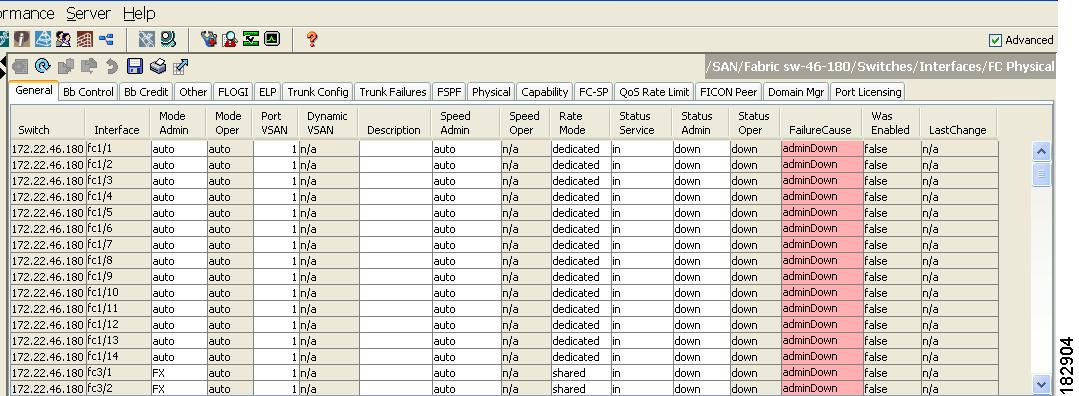
Some configuration settings are similar for Fibre Channel, management, and VSAN interfaces. You can configure interfaces from Fabric Manager by expanding Switches > Interfaces and selecting the interface type from the Physical Attributes pane.
Figure 2-1 shows a sample of what you might see in the Information pane for Fibre Channel interfaces.
Figure 2-1 Fibre Channel Interface Configuration
Fibre Channel Interfaces
This section describes Fibre Channel interface characteristics, including (but not limited to) modes, frame encapsulation, states, SFPs, and speeds.
This section includes the following topics:
•![]() Generation 1 Interfaces Configuration Guidelines
Generation 1 Interfaces Configuration Guidelines
•![]() Configuring Administrative Speeds
Configuring Administrative Speeds
•![]() Displaying SFP Transmitter Types
Displaying SFP Transmitter Types
Generation 1 Interfaces Configuration Guidelines
The 32-port switching module guidelines apply to the following hardware:
•![]() The 32-port, 2-Gbps or 1-Gbps switching module
The 32-port, 2-Gbps or 1-Gbps switching module
•![]() The Cisco MDS 9124 and 9134 switches
The Cisco MDS 9124 and 9134 switches

Note ![]() Due to the hardware design of the MDS 9134 switch, we do not support interface out-of-service action on either of its two 10-Gigabit ports. This is because no internal port hardware resource is released when an out-of-service action is performed on these 10-Gigabit ports.
Due to the hardware design of the MDS 9134 switch, we do not support interface out-of-service action on either of its two 10-Gigabit ports. This is because no internal port hardware resource is released when an out-of-service action is performed on these 10-Gigabit ports.
When configuring these host-optimized ports, the following port mode guidelines apply:
•![]() You can configure only the first port in each 4-port group (for example, the first port in ports 1-4, the fifth port in ports 5-8, and so on) as an E port. If the first port in the group is configured as an E port, the other three ports in each group (ports 2-4, 6-8, and so on) are not usable and remain shutdown.
You can configure only the first port in each 4-port group (for example, the first port in ports 1-4, the fifth port in ports 5-8, and so on) as an E port. If the first port in the group is configured as an E port, the other three ports in each group (ports 2-4, 6-8, and so on) are not usable and remain shutdown.
•![]() If you execute the write erase command on a 32-port switching module, and then copy a saved configuration to the switch from a text file that contains the no system default switchport shutdown command, you need to copy the text file to the switch again for the E ports to come up without manual configuration.
If you execute the write erase command on a 32-port switching module, and then copy a saved configuration to the switch from a text file that contains the no system default switchport shutdown command, you need to copy the text file to the switch again for the E ports to come up without manual configuration.
•![]() If any of the other three ports are enabled, you cannot configure the first port as an E port. The other three ports continue to remain enabled.
If any of the other three ports are enabled, you cannot configure the first port as an E port. The other three ports continue to remain enabled.
•![]() The auto mode is not allowed in a 32-port switching module or the host-optimized ports in the Cisco 9100 Series (16 host-optimized ports in the Cisco MDS 9120 switch and 32 host-optimized ports in the Cisco MDS 9140 switch).
The auto mode is not allowed in a 32-port switching module or the host-optimized ports in the Cisco 9100 Series (16 host-optimized ports in the Cisco MDS 9120 switch and 32 host-optimized ports in the Cisco MDS 9140 switch).
•![]() The default port mode is Fx (Fx negotiates to F or FL) for 32-port switching modules.
The default port mode is Fx (Fx negotiates to F or FL) for 32-port switching modules.
•![]() The 32-port switching module does not support FICON.
The 32-port switching module does not support FICON.
Note ![]() We recommend that you configure your E ports on a 16-port switching module. If you must configure an E port on a 32-port host-optimized switching module, the other three ports in that 4-port group cannot be used.
We recommend that you configure your E ports on a 16-port switching module. If you must configure an E port on a 32-port host-optimized switching module, the other three ports in that 4-port group cannot be used.
Note ![]() In the Cisco MDS 9100 Series, the groups of ports that are located on the left and outlined in white are full line rate. The other ports are host-optimized. Each group of 4 host-optimized ports have the same features as for the 32-port switching module.
In the Cisco MDS 9100 Series, the groups of ports that are located on the left and outlined in white are full line rate. The other ports are host-optimized. Each group of 4 host-optimized ports have the same features as for the 32-port switching module.
About Interface Modes
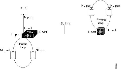
Each physical Fibre Channel interface in a switch may operate in one of several port modes: E port, F port, FL port, TL port, TE port, SD port, ST port, and B port (see Figure 2-2). Besides these modes, each interface may be configured in auto or Fx port modes. These two modes determine the port type during interface initialization.
Figure 2-2 Cisco MDS 9000 Family Switch Port Modes
Note ![]() Interfaces are created in VSAN 1 by default. See the Cisco MDS 9000 Family NX-OS Fabric Configuration Guide.
Interfaces are created in VSAN 1 by default. See the Cisco MDS 9000 Family NX-OS Fabric Configuration Guide.
Each interface has an associated administrative configuration and an operational status:
•![]() The administrative configuration does not change unless you modify it. This configuration has various attributes that you can configure in administrative mode.
The administrative configuration does not change unless you modify it. This configuration has various attributes that you can configure in administrative mode.
•![]() The operational status represents the current status of a specified attribute like the interface speed. This status cannot be changed and is read-only. Some values may not be valid when the interface is down (for example, the operational speed).
The operational status represents the current status of a specified attribute like the interface speed. This status cannot be changed and is read-only. Some values may not be valid when the interface is down (for example, the operational speed).
Note ![]() When a module is removed and replaced with the same type of module, the configuration is retained. If a different type of module is inserted, then the original configuration is no longer retained.
When a module is removed and replaced with the same type of module, the configuration is retained. If a different type of module is inserted, then the original configuration is no longer retained.
Each interface is briefly described in the sections that follow.
E Port
In expansion port (E port) mode, an interface functions as a fabric expansion port. This port may be connected to another E port to create an Inter-Switch Link (ISL) between two switches. E ports carry frames between switches for configuration and fabric management. They serve as a conduit between switches for frames destined to remote N ports and NL ports. E ports support class 2, class 3, and class F service.
An E port connected to another switch may also be configured to form a PortChannel (see Chapter 8, "Configuring PortChannels").
Note ![]() We recommend that you configure E ports on 16-port modules. If you must configure an E port on a 32-port oversubscribed module, then you can only use the first port in a group of four ports (for example, ports 1 through 4, 5 through 8, and so forth). The other three ports cannot be used.
We recommend that you configure E ports on 16-port modules. If you must configure an E port on a 32-port oversubscribed module, then you can only use the first port in a group of four ports (for example, ports 1 through 4, 5 through 8, and so forth). The other three ports cannot be used.
F Port
In fabric port (F port) mode, an interface functions as a fabric port. This port may be connected to a peripheral device (host or disk) operating as an N port. An F port can be attached to only one N port. F ports support class 2 and class 3 service.
FL Port
In fabric loop port (FL port) mode, an interface functions as a fabric loop port. This port may be connected to one or more NL ports (including FL ports in other switches) to form a public arbitrated loop. If more than one FL port is detected on the arbitrated loop during initialization, only one FL port becomes operational and the other FL ports enter nonparticipating mode. FL ports support class 2 and class 3 service.
Note ![]() FL port mode is not supported on 4-port 10-Gbps switching module interfaces.
FL port mode is not supported on 4-port 10-Gbps switching module interfaces.
NP Ports
An NP port is a port on a device that is in NPV mode and connected to the core switch via an F port. NP ports function like N ports except that in addition to providing N port operations, they also function as proxies for multiple, physical N ports.
For more details about NP ports and NPV, see Chapter 9, "Configuring N Port Virtualization."
TL Port
In translative loop port (TL port) mode, an interface functions as a translative loop port. It may be connected to one or more private loop devices (NL ports). TL ports are specific to Cisco MDS 9000 Family switches and have similar properties as FL ports. TL ports enable communication between a private loop device and one of the following devices:
•![]() A device attached to any switch on the fabric
A device attached to any switch on the fabric
•![]() A device on a public loop anywhere in the fabric
A device on a public loop anywhere in the fabric
•![]() A device on a different private loop anywhere in the fabric
A device on a different private loop anywhere in the fabric
•![]() A device on the same private loop
A device on the same private loop
TL ports support class 2 and class 3 services.
Private loop devices refer to legacy devices that reside on arbitrated loops. These devices are not aware of a switch fabric because they only communicate with devices on the same physical loop (see the "About TL Port ALPA Caches" section).
Tip ![]() We recommend configuring devices attached to TL ports in zones that have up to 64 zone members.
We recommend configuring devices attached to TL ports in zones that have up to 64 zone members.
Note ![]() TL port mode is not supported on Generation 2 switching module interfaces.
TL port mode is not supported on Generation 2 switching module interfaces.
TE Port
In trunking E port (TE port) mode, an interface functions as a trunking expansion port. It may be connected to another TE port to create an extended ISL (EISL) between two switches. TE ports are specific to Cisco MDS 9000 Family switches. They expand the functionality of E ports to support the following:
•![]() VSAN trunking
VSAN trunking
•![]() Transport quality of service (QoS) parameters
Transport quality of service (QoS) parameters
•![]() Fibre Channel trace (fctrace) feature
Fibre Channel trace (fctrace) feature
In TE port mode, all frames are transmitted in EISL frame format, which contains VSAN information. Interconnected switches use the VSAN ID to multiplex traffic from one or more VSANs across the same physical link. This feature is referred to as trunking in the Cisco MDS 9000 Family (see Chapter 7, "Configuring Trunking"). TE ports support class 2, class 3, and class F service.
TF Port
In trunking F port (TF port) mode, an interface functions as a trunking expansion port. It may be connected to another trunked N port (TN port) or trunked NP port (TNP port) to create a link between a core switch and an NPV switch or an HBA to carry tagged frames. TF ports are specific to Cisco MDS 9000 Family switches. They expand the functionality of F ports to support VSAN trunking.
In TF port mode, all frames are transmitted in EISL frame format, which contains VSAN information. Interconnected switches use the VSAN ID to multiplex traffic from one or more VSANs across the same physical link. This feature is referred to as trunking in the Cisco MDS 9000 Family (see Chapter 7, "Configuring Trunking"). TF ports support class 2, class 3, and class F service.
TNP Port
In trunking NP port (TNP port) mode, an interface functions as a trunking expansion port. It may be connected to a trunked F port (TF port) to create a link to a core NPIV switch from an NPV switch to carry tagged frames.
SD Port
In SPAN destination port (SD port) mode, an interface functions as a switched port analyzer (SPAN). The SPAN feature is specific to switches in the Cisco MDS 9000 Family. It monitors network traffic that passes though a Fibre Channel interface. This monitoring is done using a standard Fibre Channel analyzer (or a similar switch probe) that is attached to an SD port. SD ports do not receive frames, they only transmit a copy of the source traffic. The SPAN feature is nonintrusive and does not affect switching of network traffic for any SPAN source ports (see the Cisco MDS 9000 Family NX-OS System Management Configuration Guide).
ST Port
In the SPAN tunnel port (ST port) mode, an interface functions as an entry point port in the source switch for the RSPAN Fibre Channel tunnel. The ST port mode and the remote SPAN (RSPAN) feature are specific to switches in the Cisco MDS 9000 Family. When configured in ST port mode, the interface cannot be attached to any device, and thus cannot be used for normal Fibre Channel traffic (see the Cisco MDS 9000 Family NX-OS System Management Configuration Guide).
Note ![]() ST port mode is not supported on the Cisco MDS 9124 Fabric Switch, the Cisco Fabric Switch for HP c-Class BladeSystem, and the Cisco Fabric Switch for IBM BladeCenter.
ST port mode is not supported on the Cisco MDS 9124 Fabric Switch, the Cisco Fabric Switch for HP c-Class BladeSystem, and the Cisco Fabric Switch for IBM BladeCenter.
Fx Port
Interfaces configured as Fx ports can operate in either F port or FL port mode. The Fx port mode is determined during interface initialization depending on the attached N port or NL port. This administrative configuration disallows interfaces to operate in any other mode—for example, preventing an interface to connect to another switch.
B Port
While E ports typically interconnect Fibre Channel switches, some SAN extender devices, such as the Cisco PA-FC-1G Fibre Channel port adapter, implement a bridge port (B port) model to connect geographically dispersed fabrics. This model uses B ports as described in the T11 Standard FC-BB-2.
If an FCIP peer is a SAN extender device that only supports Fibre Channel B ports, you need to enable the B port mode for the FCIP link. When a B port is enabled, the E port functionality is also enabled and they coexist. If the B port is disabled, the E port functionality remains enabled (see the Cisco MDS 9000 Family NX-OS IP Services Configuration Guide).
Auto Mode
Interfaces configured in auto mode can operate in one of the following modes: F port, FL port, E port, TE port, or TF port. The port mode is determined during interface initialization. For example, if the interface is connected to a node (host or disk), it operates in F port or FL port mode depending on the N port or NL port mode. If the interface is attached to a third-party switch, it operates in E port mode. If the interface is attached to another switch in the Cisco MDS 9000 Family, it may become operational in TE port mode (see Chapter 7, "Configuring Trunking").
TL ports and SD ports are not determined during initialization and are administratively configured.
Note ![]() Fibre Channel interfaces on Storage Services Modules (SSMs) cannot be configured in auto mode.
Fibre Channel interfaces on Storage Services Modules (SSMs) cannot be configured in auto mode.
About Interface States
The interface state depends on the administrative configuration of the interface and the dynamic state of the physical link.
Administrative States
The administrative state refers to the administrative configuration of the interface as described in Table 2-1.
Operational States
The operational state indicates the current operational state of the interface as described in Table 2-2.
Reason Codes
Reason codes are dependent on the operational state of the interface as described in Table 2-3.
|
|
|
|
|---|---|---|
Up |
Up |
None. |
Down |
Down |
Administratively down—If you administratively configure an interface as down, you disable the interface. No traffic is received or transmitted. |
Up |
Down |
See Table 2-4. |
Note ![]() Only some of the reason codes are listed in Table 2-4.
Only some of the reason codes are listed in Table 2-4.
If the administrative state is up and the operational state is down, the reason code differs based on the nonoperational reason code as described in Table 2-4.
For the Cisco Fabric Switch for HP c-Class BladeSystem and the Cisco Fabric Switch for IBM BladeCenter, you can configure a range of interfaces among internal ports or external ports, but you cannot mix both interface types within the same range. For example, "bay 1-10, bay 12" or "ext 0, ext 15-18" are valid ranges, but "bay 1-5, ext 15-17" is not.
Graceful Shutdown
Interfaces on a port are shut down by default (unless you modified the initial configuration).
The Cisco NX-OS software implicitly performs a graceful shutdown in response to either of the following actions for interfaces operating in the E port mode:
•![]() If you shut down an interface.
If you shut down an interface.
•![]() If a Cisco NX-OS software application executes a port shutdown as part of its function.
If a Cisco NX-OS software application executes a port shutdown as part of its function.
A graceful shutdown ensures that no frames are lost when the interface is shutting down. When a shutdown is triggered either by you or the Cisco NX-OS software, the switches connected to the shutdown link coordinate with each other to ensure that all frames in the ports are safely sent through the link before shutting down. This enhancement reduces the chance of frame loss.
A graceful shutdown is not possible in the following situations:
•![]() If you physically remove the port from the switch.
If you physically remove the port from the switch.
•![]() If in-order delivery (IOD) is enabled (for information about IOD, refer to the Cisco MDS 9000 Family NX-OS Fabric Configuration Guide).
If in-order delivery (IOD) is enabled (for information about IOD, refer to the Cisco MDS 9000 Family NX-OS Fabric Configuration Guide).
•![]() If the Min_LS_interval interval is higher than 10 seconds ().
If the Min_LS_interval interval is higher than 10 seconds ().
Note ![]() This feature is only triggered if both switches at either end of this E port interface are MDS switches and are running Cisco SAN-OS Release 2.0(1b) or later, or MDS NX-OS Release 4.1(1a) or later.
This feature is only triggered if both switches at either end of this E port interface are MDS switches and are running Cisco SAN-OS Release 2.0(1b) or later, or MDS NX-OS Release 4.1(1a) or later.
Setting the Interface Administrative State
To disable or enable an interface using Fabric Manager, follow these steps:
Step 1 ![]() Either expand Switches > Interfaces and then select Gigabit Ethernet or expand Switches > Interfaces and then select FC Physical. You see the interface configuration in the Information pane.
Either expand Switches > Interfaces and then select Gigabit Ethernet or expand Switches > Interfaces and then select FC Physical. You see the interface configuration in the Information pane.
Step 2 ![]() Click the General tab.
Click the General tab.
Step 3 ![]() Click Admin.
Click Admin.
You see the drop-down box shown in Figure 2-3.
Figure 2-3 Changing the Administrative Status of a Switch
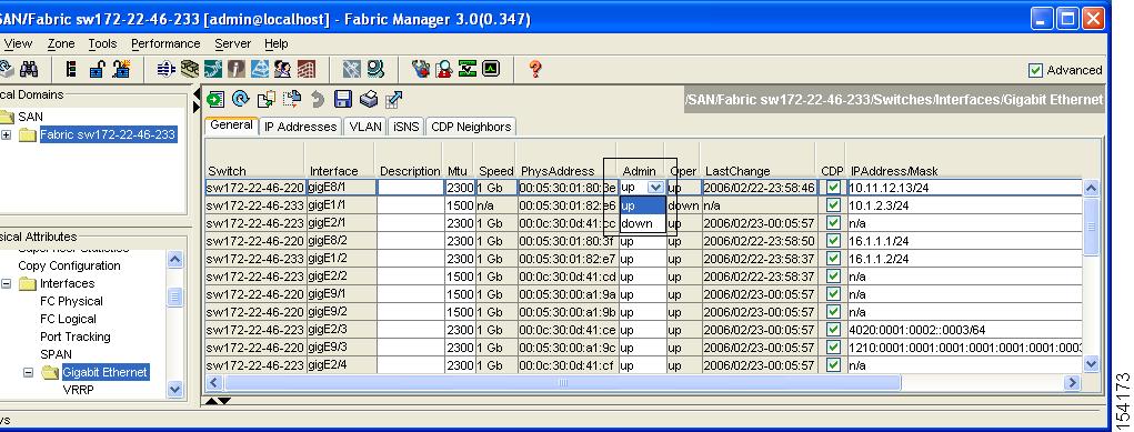
Step 4 ![]() Set the status to down (disable) or up (enable).
Set the status to down (disable) or up (enable).
Step 5 ![]() (Optional) Set other configuration parameters using the other tabs.
(Optional) Set other configuration parameters using the other tabs.
Step 6 ![]() Click Apply Changes.
Click Apply Changes.
Configuring Interface Modes
Note ![]() To ensure that ports that are part of ISLs do not get changed to port mode F, configure the ports in port mode E, rather than in Auto mode.
To ensure that ports that are part of ISLs do not get changed to port mode F, configure the ports in port mode E, rather than in Auto mode.
To configure the interface mode using Fabric Manager, follow these steps:
Step 1 ![]() Expand Switches > Interfaces, and then select FC Physical.
Expand Switches > Interfaces, and then select FC Physical.
You see the interface configuration in the Information pane.
Step 2 ![]() Click the General tab.
Click the General tab.
Step 3 ![]() Click Mode Admin. Set the desired interface mode from the Admin drop-down menu.
Click Mode Admin. Set the desired interface mode from the Admin drop-down menu.
Step 4 ![]() (Optional) Set other configuration parameters using the other tabs.
(Optional) Set other configuration parameters using the other tabs.
Step 5 ![]() Click Apply Changes icon.
Click Apply Changes icon.
Configuring Administrative Speeds
By default, the port administrative speed for an interface is automatically calculated by the switch.

To configure administrative speed of the interface using Fabric Manager, follow these steps:
Step 1 ![]() Expand Switches > Interfaces, and then select FC Physical.
Expand Switches > Interfaces, and then select FC Physical.
You see the interface configuration in the Information pane.
Step 2 ![]() Click the General tab.
Click the General tab.
Step 3 ![]() Click Speed Admin. Set the desired speed from the drop-down menu.
Click Speed Admin. Set the desired speed from the drop-down menu.
The number indicates the speed in megabits per second (Mbps). You can set the speed to 1-Gbps, 2-Gbps, 4-Gbps, 8-Gbps, or auto (default).
Note ![]() On a Cisco Nexus 5000 Series switch that runs Cisco NX-OS Release 4.2(2), you can configure the 8-Gbps administrative speed only on an M1060 switch module. You can configure the speed to 1 Gbps, 2 Gbps, or 4 Gbps on all switch modules on a Cisco Nexus 5000 Series switch that runs Cisco NX-OS Release 4.2(2) or earlier releases.
On a Cisco Nexus 5000 Series switch that runs Cisco NX-OS Release 4.2(2), you can configure the 8-Gbps administrative speed only on an M1060 switch module. You can configure the speed to 1 Gbps, 2 Gbps, or 4 Gbps on all switch modules on a Cisco Nexus 5000 Series switch that runs Cisco NX-OS Release 4.2(2) or earlier releases.
Step 4 ![]() Click Apply Changes.
Click Apply Changes.
For internal ports on the Cisco Fabric Switch for HP c_Class BladeSystem and Cisco Fabric Switch for IBM BladeCenter, a port speed of 1 Gbps is not supported. Auto-negotiation is supported between 2 Gbps and 4 Gbps only. Also, if the BladeCenter is a T chassis, then port speeds are fixed at 2 Gbps and auto-negotiation is not enabled.
Autosensing
Autosensing speed is enabled on all 4-Gbps and 8-Gbps switching module interfaces by default. This configuration enables the interfaces to operate at speeds of 1 Gbps, 2 Gbps, or 4 Gbps on the 4-Gbps switching modules, and 8 Gbps on the 8-Gbps switching modules. When autosensing is enabled for an interface operating in dedicated rate mode, 4 Gbps of bandwidth is reserved, even if the port negotiates at an operating speed of 1 Gbps or 2 Gbps.
To avoid wasting unused bandwidth on 48-port and 24-port 4-Gbps and 8-Gbps Fibre Channel switching modules, you can specify that only 2 Gbps of required bandwidth be reserved, not the default of 4 Gbps or 8 Gbps. This feature shares the unused bandwidth within the port group provided that it does not exceed the rate limit configuration for the port. You can also use this feature for shared rate ports that are configured for autosensing.
Tip ![]() When migrating a host that supports up to 2-Gbps traffic (that is, not 4 Gbps with autosensing capabilities) to the 4-Gbps switching modules, use autosensing with a maximum bandwidth of 2 Gbps. When migrating a host that supports up to 4-Gbps traffic (that is, not 8 Gbps with autosensing capabilities) to the 8-Gbps switching modules, use autosensing with a maximum bandwidth of 4 Gbps.
When migrating a host that supports up to 2-Gbps traffic (that is, not 4 Gbps with autosensing capabilities) to the 4-Gbps switching modules, use autosensing with a maximum bandwidth of 2 Gbps. When migrating a host that supports up to 4-Gbps traffic (that is, not 8 Gbps with autosensing capabilities) to the 8-Gbps switching modules, use autosensing with a maximum bandwidth of 4 Gbps.
About Interface Descriptions
Interface descriptions enable you to identify the traffic or the use for that interface. The interface description can be any alphanumeric string.
Specifying a Port Owner
Using the port owner feature, you can specify the owner of a port and the purpose for which a port is used so that the other administrators are informed.
Note ![]() The port guard and port owner features are available for all ports regardless of the operational mode.
The port guard and port owner features are available for all ports regardless of the operational mode.
To specify or remove the port owner using the Fabric Manager, follow these steps:
Step 1 ![]() Expand Switches > Interfaces and then select FC Physical.
Expand Switches > Interfaces and then select FC Physical.
You see the interface configuration in the Information pane.
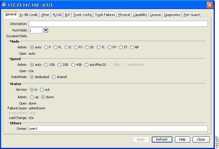
Step 2 ![]() Click the General tab (see Figure 2-4) and then select the port.
Click the General tab (see Figure 2-4) and then select the port.
Figure 2-4 Fabric Manager - Port Owner

Step 3 ![]() In the Owner text box, enter a port owner and the purpose for which port is used.
In the Owner text box, enter a port owner and the purpose for which port is used.
To specify or remove the port owner using the Device Manager, follow these steps:
Step 1 ![]() Double-click the interface in the modules panel.
Double-click the interface in the modules panel.
Step 2 ![]() Click the General tab.
Click the General tab.
Figure 2-5 Device Manager - Port Owner
Step 3 ![]() In the Owner text box, enter a port owner and the purpose for which the port is used.
In the Owner text box, enter a port owner and the purpose for which the port is used.
Step 4 ![]() Click Apply.
Click Apply.
Displaying the Owned Ports
To display the interfaces owned using the Device Manager, follow these steps:
Step 1 ![]() Click on the Ports All drop-down button, from the menu bar.
Click on the Ports All drop-down button, from the menu bar.
Figure 2-6 Device Manager - Ports Owned

Step 2 ![]() Select Ports Owned from the drop-down list.
Select Ports Owned from the drop-down list.
About Frame Encapsulation
You can set the frame format to EISL for all frames transmitted by the interface in SD port mode. If you sent the frame encapsulation to EISL, all outgoing frames are transmitted in the EISL frame format, regardless of the SPAN sources. See the Cisco MDS 9000 Family NX-OS System Management Configuration Guide.
Refer to the Cisco MDS 9000 Family NX-OS Interfaces Configuration Guide to configure frame encapsulation on an interface.
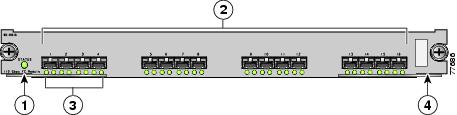
Identifying the Beacon LEDs
Figure 2-7 displays the status, link, and speed LEDs in a 16-port switching module.
Figure 2-7 Cisco MDS 9000 Family Switch Interface Modes
|
|
Status LED1 |
|
Link LEDs1 and speed LEDs2 |
|
|
1/2-Gbps Fibre Channel port group |
|
Asset tag3 |
1 See the Cisco MDS 9000 Family NX-OS Fundamentals Configuration Guide. 2 See the "About Speed LEDs" section. 3 Refer to the Cisco MDS 9000 Family hardware installation guide for your platform. |
About Speed LEDs
Each port has one link LED on the left and one speed LED on the right.
The speed LED displays the speed of the port interface:
•![]() Off—The interface attached to that port is functioning at 1000 Mbps.
Off—The interface attached to that port is functioning at 1000 Mbps.
•![]() On (solid green)—The interface attached to that port is functioning at 2000 Mbps (for 2 Gbps interfaces).
On (solid green)—The interface attached to that port is functioning at 2000 Mbps (for 2 Gbps interfaces).
The speed LED also displays if the beacon mode is enabled or disabled:
•![]() Off or solid green—Beacon mode is disabled.
Off or solid green—Beacon mode is disabled.
•![]() Flashing green—The beacon mode is enabled. The LED flashes at one-second intervals.
Flashing green—The beacon mode is enabled. The LED flashes at one-second intervals.
Note ![]() Generation 2 and Generation 3 modules and fabric switches do not have speed LEDs.
Generation 2 and Generation 3 modules and fabric switches do not have speed LEDs.
About Beacon Mode
By default, the beacon mode is disabled on all switches. The beacon mode is indicated by a flashing green light that helps you identify the physical location of the specified interface.
Configuring the beacon mode has no effect on the operation of the interface.
Configuring Beacon Mode
To enable beacon mode for a specified interface or range of interfaces using Fabric Manager, follow these steps:
Step 1 ![]() Expand Switches > Interfaces and then select Gigabit Ethernet.
Expand Switches > Interfaces and then select Gigabit Ethernet.
You see the interface configuration in the Information pane.
Step 2 ![]() Enable the Beacon Mode option for the selected switch.
Enable the Beacon Mode option for the selected switch.
Step 3 ![]() Click Apply Changes.
Click Apply Changes.
Note ![]() The flashing green light turns on automatically when an external loopback is detected that causes the interfaces to be isolated. The flashing green light overrides the beacon mode configuration. The state of the LED is restored to reflect the beacon mode configuration after the external loopback is removed.
The flashing green light turns on automatically when an external loopback is detected that causes the interfaces to be isolated. The flashing green light overrides the beacon mode configuration. The state of the LED is restored to reflect the beacon mode configuration after the external loopback is removed.
About Bit Error Thresholds
The bit error rate threshold is used by the switch to detect an increased error rate before performance degradation seriously affects traffic.
The bit errors can occur for the following reasons:
•![]() Faulty or bad cable.
Faulty or bad cable.
•![]() Faulty or bad GBIC or SFP.
Faulty or bad GBIC or SFP.
•![]() GBIC or SFP is specified to operate at 1 Gbps but is used at 2 Gbps.
GBIC or SFP is specified to operate at 1 Gbps but is used at 2 Gbps.
•![]() GBIC or SFP is specified to operate at 2 Gbps but is used at 4 Gbps.
GBIC or SFP is specified to operate at 2 Gbps but is used at 4 Gbps.
•![]() Short haul cable is used for long haul or long haul cable is used for short haul.
Short haul cable is used for long haul or long haul cable is used for short haul.
•![]() Momentary sync loss.
Momentary sync loss.
•![]() Loose cable connection at one or both ends.
Loose cable connection at one or both ends.
•![]() Improper GBIC or SFP connection at one or both ends.
Improper GBIC or SFP connection at one or both ends.
A bit error rate threshold is detected when 15 error bursts occur in a 5-minute period. By default, the switch disables the interface when the threshold is reached. You can enter a shutdown and no shutdown command sequence to reenable the interface.
You can configure the switch to not disable an interface when the threshold is crossed. By default, the threshold disables the interface.
Refer to the Cisco MDS 9000 Family NX-OS Interfaces Configuration Guide to disable the bit error threshold for an interface.
Note ![]() Regardless of disabling the switch port ignore bit-error threshold for an interface, the switch generates a syslog message when bit-error threshold events are detected.
Regardless of disabling the switch port ignore bit-error threshold for an interface, the switch generates a syslog message when bit-error threshold events are detected.
Switch Port Attribute Default Values
You can configure attribute default values for various switch port attributes. These attributes will be applied globally to all future switch port configurations, even if you do not individually specify them at that time.
Refer to the Cisco MDS 9000 Family NX-OS Interfaces Configuration Guide to configure switch port attributes.
About SFP Transmitter Types
The small form-factor pluggable (SFP) hardware transmitters are identified by their acronyms when displayed. Table 2-5 defines the acronyms used for SFPs (see the "Displaying SFP Transmitter Types" section).
Displaying SFP Transmitter Types
To show the SFP types for an interface using Fabric Manager, follow these steps:
Step 1 ![]() Expand Switches > Interfaces and then select FC Physical. You see the interface configuration in the Information pane.
Expand Switches > Interfaces and then select FC Physical. You see the interface configuration in the Information pane.
Step 2 ![]() Click the Physical tab to see the transmitter type for the selected interface.
Click the Physical tab to see the transmitter type for the selected interface.
About Gathering Interface Statistics
You can use Fabric Manager or Device Manager to collect interface statistics on any switch. These statistics are collected at intervals that you can set.
Gathering Interface Statistics
Note ![]() In Fabric Manager, you can collect interface statistics by expanding Switches > ISLs and selecting Statistics from the Physical Attributes pane.
In Fabric Manager, you can collect interface statistics by expanding Switches > ISLs and selecting Statistics from the Physical Attributes pane.
To gather and display interface counters using Device Manager, follow these steps:
Step 1 ![]() Right-click an interface and select Monitor.
Right-click an interface and select Monitor.
You see the Interface Monitor dialog box.
Step 2 ![]() Set both the number of seconds at which you want to poll the interface statistics and how you want the data represented in the Interval drop-down menus. For example, click 10s and LastValue/sec.
Set both the number of seconds at which you want to poll the interface statistics and how you want the data represented in the Interval drop-down menus. For example, click 10s and LastValue/sec.
Step 3 ![]() Select any tab shown in Figure 2-8 to view those related statistics.
Select any tab shown in Figure 2-8 to view those related statistics.
Figure 2-8 Device Manager Interface Monitor Dialog Box
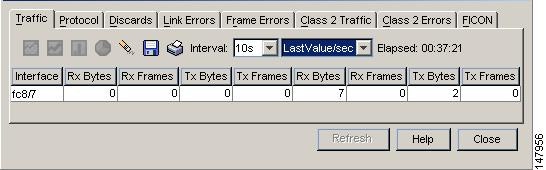
Step 4 ![]() (Optional) Click the Pencil icon to reset the cumulative counters.
(Optional) Click the Pencil icon to reset the cumulative counters.
Step 5 ![]() (Optional) Click the Save icon to save the gathered statistics to a file or select the Print icon to print the statistics.
(Optional) Click the Save icon to save the gathered statistics to a file or select the Print icon to print the statistics.
Step 6 ![]() Click Close when you are finished gathering and displaying statistics.
Click Close when you are finished gathering and displaying statistics.
TL Ports for Private Loops
Private loops require setting the interface mode to TL. This section describes TL ports and includes the following sections:
About TL Ports
TL port mode is not supported on the following:
•![]() Generation 2 switching module interfaces
Generation 2 switching module interfaces
•![]() Cisco MDS 9124 Fabric Switch
Cisco MDS 9124 Fabric Switch
•![]() Cisco Fabric Switch for HP c-Class BladeSystem
Cisco Fabric Switch for HP c-Class BladeSystem
•![]() Cisco Fabric Switch for IBM BladeCenter
Cisco Fabric Switch for IBM BladeCenter
Private loop devices refer to legacy devices that reside on arbitrated loops. These devices are not aware of a switch fabric because they only communicate with devices on the same physical loop.
The legacy devices are used in Fibre Channel networks and devices outside the loop may need to communicate with them. The communication functionality is provided through TL ports. See the "About Interface Modes" section.
Follow these guidelines when configuring private loops:
•![]() A maximum of 64 fabric devices can be proxied to a private loop.
A maximum of 64 fabric devices can be proxied to a private loop.
•![]() Fabric devices must be in the same zone as private loop devices to be proxied to the private loop.
Fabric devices must be in the same zone as private loop devices to be proxied to the private loop.
•![]() Each private device on a TL port may be included in a different zone.
Each private device on a TL port may be included in a different zone.
•![]() All devices on the loop are treated as private loops. You cannot mix private and public devices on the loop if the configured port mode is TL.
All devices on the loop are treated as private loops. You cannot mix private and public devices on the loop if the configured port mode is TL.
•![]() The only FC4-type supported by TL ports is SCSI (FCP).
The only FC4-type supported by TL ports is SCSI (FCP).
•![]() Communication between a private initiator to a private target on the same private loop does not invoke TL port services.
Communication between a private initiator to a private target on the same private loop does not invoke TL port services.
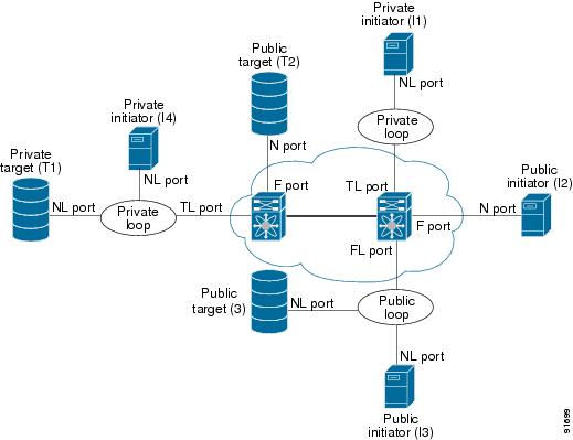
Table 2-6 lists the TL port translations supported in Cisco MDS 9000 Family switches. Figure 2-9 shows examples of TL port translation support.
Figure 2-9 TL Port Translation Support Examples
Configuring TL Ports
To configure the TL interface mode using Fabric Manager, follow these steps:
Step 1 ![]() Expand Switches > Interfaces and then select FC Physical. You see the interface configuration in the Information pane.
Expand Switches > Interfaces and then select FC Physical. You see the interface configuration in the Information pane.
Step 2 ![]() Click the General tab and click Mode Admin.
Click the General tab and click Mode Admin.
Step 3 ![]() Set the Mode Admin drop-down menu to TL.
Set the Mode Admin drop-down menu to TL.
Step 4 ![]() (Optional) Set other configuration parameters using the other tabs.
(Optional) Set other configuration parameters using the other tabs.
Step 5 ![]() Click Apply Changes.
Click Apply Changes.
About TL Port ALPA Caches
Although TL ports cannot be automatically configured, you can manually configure entries in arbitrated loop physical address (ALPA) caches. Generally, ALPA cache entries are automatically populated when an ALPA is assigned to a device. Each device is identified by its port world wide name (pWWN). When a device is allocated an ALPA, an entry for that device is automatically created in the ALPA cache.
A cache contains entries for recently allocated ALPA values. These caches are maintained on various TL ports. If a device already has an ALPA, the Cisco NX-OS software attempts to allocate the same ALPA to the device each time. The ALPA cache is maintained in persistent storage and saves information across switch reboots. The maximum cache size is 1000 entries. If the cache is full, and a new ALPA is allocated, the Cisco NX-OS software discards an inactive cache entry (if available) to make space for the new entry. See the "TL Port" section for more information on TL ports.
Refer to the Cisco MDS 9000 Family NX-OS Interfaces Configuration Guide to manage the TL Port ALPA cache.
Configuring Port Guard
The port guard feature is intended for use in environments where the system and application environment does not adapt quickly and efficiently to a port going down and back up, or to a port rapidly cycling up and down, which can happen in some failure modes. For example, if a system takes five seconds to stabilize after a port goes down, but the port is going up and down once a second, this might ultimately cause a more severe failure in the fabric.
The port guard feature gives the SAN administrator the ability to prevent this issue from occurring in environments that are vulnerable to these problems. The port can be configured to stay down after the first failure, or after specified number of failures in a specified time period. This allows the SAN administrator to intervene and control the recovery, avoiding any problems caused by the cycling.
Using the port guard feature, you can restrict the number of error reports and bring a malfunctioning port to down state dynamically. A port can be cofigured to go into error-disabled state for specific types of failures.
A general link failure caused by link-down is the superset of all other causes. The sum of the number of all other causes equals to the number of link-down link failures. This means a port is brought to down state when it reaches the maximum number of allowed link failures or the number of specific causes.
The causes of link failure can be any of the following:
•![]() ESP trustsec-violation
ESP trustsec-violation
•![]() Bit-errors
Bit-errors
•![]() Signal loss
Signal loss
•![]() Sync loss
Sync loss
•![]() Link reset
Link reset
•![]() Credit loss
Credit loss
•![]() Additional causes might be the following:
Additional causes might be the following:
–![]() Not operational (NOS).
Not operational (NOS).
–![]() Too many interrupts.
Too many interrupts.
–![]() Cable is disconnected.
Cable is disconnected.
–![]() Hardware recoverable errors.
Hardware recoverable errors.
–![]() The connected device rebooted (F ports only).
The connected device rebooted (F ports only).
–![]() The connected linecard rebooted (ISL only).
The connected linecard rebooted (ISL only).
Link down is the superset of all other causes. A port is brought to down state if the total number of other causes equals to the number of allowed link-down failures.
This example shows how to configure port guard to bring a port to down state if the link flaps 5 times within 120 seconds based on multiple causes:
Switch# config t
Switch (config)# interface fc1/1
Switch (config-if)# errdisable detect cause link-down num-times 5 duration 120
Switch (config-if)# errdisable detect cause bit-errors num-times 5 duration 120
Switch (config-if)# errdisable detect cause credit-loss num-times 5 duration 120
With this configuration:
•![]() The port will be error-disabled due to bit errors if the port suffers link failure due to bit errors 5 times in 120 seconds.
The port will be error-disabled due to bit errors if the port suffers link failure due to bit errors 5 times in 120 seconds.
•![]() The port will be error-disabled due to credit loss if the port suffers link failure due to credit loss 5 times in 120 seconds.
The port will be error-disabled due to credit loss if the port suffers link failure due to credit loss 5 times in 120 seconds.
•![]() The port will be error-disabled due to link down if the port suffers link failure due to bit errors 2 times and link-failure due to credit loss 3 times in 120 seconds.
The port will be error-disabled due to link down if the port suffers link failure due to bit errors 2 times and link-failure due to credit loss 3 times in 120 seconds.
Note ![]() Even if the link does not flap due to failure of the link, and port guard is not enabled, the port goes into a down state if too many invalid FLOGI requests are received from the same host.
Even if the link does not flap due to failure of the link, and port guard is not enabled, the port goes into a down state if too many invalid FLOGI requests are received from the same host.
To enable port guard using Fabric Manager, follow these steps:
Step 1 ![]() Expand Switches > Interfaces, and then select Port Guard from the Physical Attributes pane.
Expand Switches > Interfaces, and then select Port Guard from the Physical Attributes pane.
You see the interfaces listed in the Information pane. (Figure 2-10)
Figure 2-10 Fabric Manager - Port Guard

Step 2 ![]() Click the Link Failure tab and then select the port (see Figure 2-11).
Click the Link Failure tab and then select the port (see Figure 2-11).
Figure 2-11 Fabric Manager - Port Guard
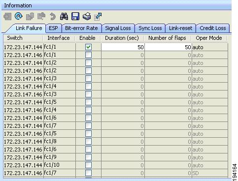
Step 3 ![]() Check the check box in the Enable column.
Check the check box in the Enable column.
Step 4 ![]() (Optional) Enter the Duration in seconds and the number of flaps. If the values are 0, the port is brought to down state if the link flaps even once. Otherwise, the link is brought to down state if the link flaps for the number of flaps within the duration.
(Optional) Enter the Duration in seconds and the number of flaps. If the values are 0, the port is brought to down state if the link flaps even once. Otherwise, the link is brought to down state if the link flaps for the number of flaps within the duration.
Step 5 ![]() Click Apply to activate the configuration.
Click Apply to activate the configuration.
Step 6 ![]() Click the ESP tab and then select the port. (Figure 2-12)
Click the ESP tab and then select the port. (Figure 2-12)
Figure 2-12 Fabric Manager - Port Guard

Step 7 ![]() Check the check box in the Enable column.
Check the check box in the Enable column.
Step 8 ![]() (Optional) Enter the duration in seconds and the number of flaps. If the values are 0, the port is brought to down state if a trustsec violation occurs even once. Otherwise, the link is brought to down state if there is trustsec violation for the number of flaps within the duration.
(Optional) Enter the duration in seconds and the number of flaps. If the values are 0, the port is brought to down state if a trustsec violation occurs even once. Otherwise, the link is brought to down state if there is trustsec violation for the number of flaps within the duration.
Step 9 ![]() Click the Bit-error Rate, Signal Loss, Sync Loss, Link-reset, and Credit Loss tabs and complete the port guard configuration.
Click the Bit-error Rate, Signal Loss, Sync Loss, Link-reset, and Credit Loss tabs and complete the port guard configuration.
Step 10 ![]() Click Apply to activate the configuration.
Click Apply to activate the configuration.
To enable port guard for single or multiple interfaces using Device Manager, follow these steps:
Step 1 ![]() From the menu bar, select Interface > Port Guard.
From the menu bar, select Interface > Port Guard.
You see the FC Interfaces listed.
Step 2 ![]() Click the Link Failure tab and then select the port.
Click the Link Failure tab and then select the port.
Step 3 ![]() Check the check box in the Enable column.
Check the check box in the Enable column.
Step 4 ![]() (Optional) Enter the duration in seconds and the number of flaps. If the values are 0, the port goes into a down state even if the link flaps once. Otherwise, the link goes into a down state if the link flaps for the number of flaps within the duration.
(Optional) Enter the duration in seconds and the number of flaps. If the values are 0, the port goes into a down state even if the link flaps once. Otherwise, the link goes into a down state if the link flaps for the number of flaps within the duration.
Step 5 ![]() Click Apply to activate the configuration.
Click Apply to activate the configuration.
Step 6 ![]() Click the ESP tab and then select the port.
Click the ESP tab and then select the port.
Step 7 ![]() Check the check box in the Enable column.
Check the check box in the Enable column.
Step 8 ![]() (Optional) Enter the Duration in seconds and the number of flaps. If the values are 0, the port is brought to down state if a trsutsec violation occurs even once. Otherwise, the link is brought to down state if a trustsec violation occurs for the number of flaps within the duration.
(Optional) Enter the Duration in seconds and the number of flaps. If the values are 0, the port is brought to down state if a trsutsec violation occurs even once. Otherwise, the link is brought to down state if a trustsec violation occurs for the number of flaps within the duration.
Step 9 ![]() Click Apply to activate the configuration.
Click Apply to activate the configuration.
Management Interfaces
You can remotely configure the switch through the management interface (mgmt0). To configure a connection on the mgmt0 interface, you must configure either the IP version 4 (IPv4) parameters (IP address, subnet mask, and default gateway) or the IP version 6 (IPv6) parameters so that the switch is reachable.
This section describes the management interfaces and includes the following topics:
•![]() Configuring Management Interfaces
Configuring Management Interfaces
About Management Interfaces
Before you begin to configure the management interface manually, obtain the switch's IPv4 address and subnet mask, or the IPv6 address.
The management port (mgmt0) is autosensing and operates in full-duplex mode at a speed of 10/100/1000 Mbps. Autosensing supports both the speed and the duplex mode. On a Supervisor-1 module, the default speed is 100 Mbps and the default duplex mode is auto. On a Supervisor-2 module, the default speed is auto and the default duplex mode is auto.
Note ![]() You need to explicitly configure a default gateway to connect to the switch and send IP packets or add a route for each subnet.
You need to explicitly configure a default gateway to connect to the switch and send IP packets or add a route for each subnet.
Configuring Management Interfaces
To configure the mgmt0 Ethernet interface using Fabric Manager, follow these steps:
Step 1 ![]() Select a VSAN in the Logical Domains pane.
Select a VSAN in the Logical Domains pane.
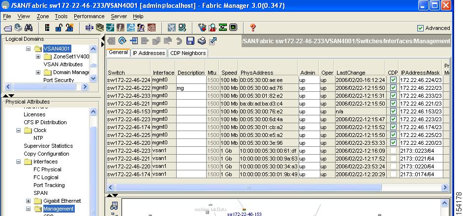
Step 2 ![]() Expand Switches > Interfaces and then select Management.
Expand Switches > Interfaces and then select Management.
You see the interface configuration in the Information pane.
Step 3 ![]() Click the General tab.
Click the General tab.
Step 4 ![]() Set the IP Address/Mask field.
Set the IP Address/Mask field.
Step 5 ![]() Set Admin to up.
Set Admin to up.
Step 6 ![]() (Optional) Set other configuration parameters using the other tabs.
(Optional) Set other configuration parameters using the other tabs.
Step 7 ![]() Click Apply Changes.
Click Apply Changes.
VSAN Interfaces
VSANs apply to Fibre Channel fabrics and enable you to configure multiple isolated SAN topologies within the same physical infrastructure. You can create an IP interface on top of a VSAN and then use this interface to send frames to this VSAN. To use this feature, you must configure the IP address for this VSAN. VSAN interfaces cannot be created for nonexisting VSANs.
This section describes VSAN interfaces and includes the following topics:
About VSAN Interfaces
Follow these guidelines when creating or deleting VSAN interfaces:
•![]() Create a VSAN before creating the interface for that VSAN. If a VSAN does not exist, the interface cannot be created.
Create a VSAN before creating the interface for that VSAN. If a VSAN does not exist, the interface cannot be created.
•![]() Create the interface VSAN—it is not created automatically.
Create the interface VSAN—it is not created automatically.
•![]() If you delete the VSAN, the attached interface is automatically deleted.
If you delete the VSAN, the attached interface is automatically deleted.
•![]() Configure each interface only in one VSAN.
Configure each interface only in one VSAN.
Tip ![]() After configuring the VSAN interface, you can configure an IP address or Virtual Router Redundancy Protocol (VRRP) feature (see the Cisco MDS 9000 Family NX-OS IP Services Configuration Guide).
After configuring the VSAN interface, you can configure an IP address or Virtual Router Redundancy Protocol (VRRP) feature (see the Cisco MDS 9000 Family NX-OS IP Services Configuration Guide).
Creating VSAN Interfaces
To create a VSAN interface using Fabric Manager, follow these steps:
Step 1 ![]() Expand Switches > Interfaces and then select Management.
Expand Switches > Interfaces and then select Management.
Figure 2-13 General Management Tab
Step 2 ![]() Click Create Row.
Click Create Row.
You see the Create Interface dialog box (see Figure 2-14).
Figure 2-14 Create Interface Dialog Box
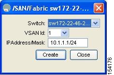
Step 3 ![]() Select the switch and VSAN ID for which you want to configure a VSAN interface.
Select the switch and VSAN ID for which you want to configure a VSAN interface.
Note ![]() You can only create a VSAN interface for an existing VSAN. If the VSAN does not exist, you cannot create a VSAN interface for it.
You can only create a VSAN interface for an existing VSAN. If the VSAN does not exist, you cannot create a VSAN interface for it.
Step 4 ![]() Set IPAddress/Mask to the IP address and subnet mask for the new VSAN interface.
Set IPAddress/Mask to the IP address and subnet mask for the new VSAN interface.
Step 5 ![]() Click Create to create the VSAN interface or click Close to close the dialog box without creating the VSAN interface.
Click Create to create the VSAN interface or click Close to close the dialog box without creating the VSAN interface.
Default Settings
Table 2-7 lists the default settings for interface parameters.
 Feedback