- Index
- New and Changed Information
- Preface
- Interfaces Overview
- Configuring Interfaces
- Configuring Ethernet Interfaces
- Configuring Virtual Interfaces
- Configuring Fibre Channel Interfaces
- Configuring Interface Buffers
- Configuring Trunking
- Configuring Port Channels
- Configuring N Port Virtualizatio
- Configuring FlexAttach Virtual pWWN
Cisco Fabric Manager Interfaces Configuration Guide
Bias-Free Language
The documentation set for this product strives to use bias-free language. For the purposes of this documentation set, bias-free is defined as language that does not imply discrimination based on age, disability, gender, racial identity, ethnic identity, sexual orientation, socioeconomic status, and intersectionality. Exceptions may be present in the documentation due to language that is hardcoded in the user interfaces of the product software, language used based on RFP documentation, or language that is used by a referenced third-party product. Learn more about how Cisco is using Inclusive Language.
- Updated:
- December 21, 2009
Chapter: Configuring Ethernet Interfaces
Configuring Ethernet Interfaces
Fabric Manager and Device Manager display configuration settings and status information about the physical Ethernet interfaces on Cisco Nexus 5000 Series switches. However, you cannot change the configuration for physical Ethernet interfaces using Fabric Manager or Device Manager.
This chapter includes the following sections:
•![]() Displaying Interface Information
Displaying Interface Information
About Ethernet Interfaces
The Ethernet ports can operate as standard Ethernet interfaces connected to servers or to a LAN. The Ethernet interfaces also support Fibre Channel over Ethernet (FCoE). FCoE allows the physical Ethernet link to carry both Ethernet and Fibre Channel traffic.
On a Cisco Nexus 5000 Series switch, the Ethernet interfaces are enabled by default.
Displaying Interface Information
Fabric Manager and Device Manager display configuration settings and status information about the physical Ethernet interfaces on Cisco Nexus 5000 Series switches.
This section describes how to display the Ethernet interface status and includes the following topics:
•![]() Displaying Interface Information Using Fabric Manager
Displaying Interface Information Using Fabric Manager
•![]() Displaying Interface Information Using Device Manager
Displaying Interface Information Using Device Manager
Displaying Interface Information Using Fabric Manager
To display Ethernet interfaces using Fabric Manager, follow these steps:
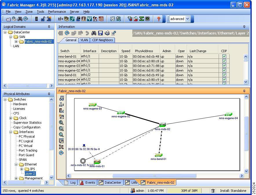
Step 1 ![]() In the Physical Attributes pane, expand Switches > Interfaces > Ethernet, and then choose Layer2.
In the Physical Attributes pane, expand Switches > Interfaces > Ethernet, and then choose Layer2.
You see the Ethernet interface information pane shown in Figure 3-1.
The General tab displays the description, speed, MAC address, and status for each Ethernet interface.
Figure 3-1 Ethernet Information Pane
Step 2 ![]() Click the VLAN tab to display the VLAN assigned to each interface.
Click the VLAN tab to display the VLAN assigned to each interface.
Step 3 ![]() Click the CDP Neighbors tab to display the CDP neighbor assigned to each interface.
Click the CDP Neighbors tab to display the CDP neighbor assigned to each interface.
Displaying Interface Information Using Device Manager
To display Ethernet interfaces using Device Manager, follow these steps:
Step 1 ![]() Launch Device Manager from the Cisco Nexus 5000 Series switch.
Launch Device Manager from the Cisco Nexus 5000 Series switch.
Step 2 ![]() Choose Interface > Ethernet.
Choose Interface > Ethernet.
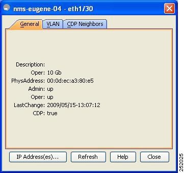
You see the Ethernet Interfaces dialog box shown in Figure 3-2.
The General tab displays the description, speed, MAC address, and status for each interface.
Figure 3-2 Ethernet Interfaces Dialog Box
Step 3 ![]() Click the VLAN tab to display the VLAN assigned to each interface.
Click the VLAN tab to display the VLAN assigned to each interface.
Step 4 ![]() Click the CDP Neighbors tab to display the CDP neighbor assigned to each interface.
Click the CDP Neighbors tab to display the CDP neighbor assigned to each interface.
Default Settings
Table 3-1 lists the default settings for all physical Ethernet interfaces.
|
|
|
|---|---|
Oper Speed |
10 GB |
Admin Status |
Up |
CDP |
True |
VLAN Type |
Static |
VLAN List |
1 |
 Feedback