Cabinet and Rack Requirements
-
Standard perforated cabinets
-
Solid-walled cabinets with a roof fan tray (bottom to top cooling)
-
Standard open racks
-
Telco racks
 Note |
If you are selecting an enclosed cabinet, we recommend one of the thermally validated types listed above: standard perforated or solid-walled with a fan tray. |
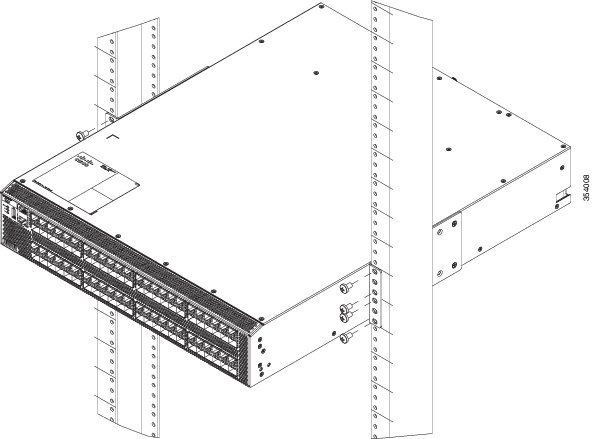
General Requirements for Cabinets and Racks
-
Standard 19 in. four-post EIA cabinet or rack, with mounting rails that conform to English universal hole spacing per section 1 of ANSI/EIA-310-D-1992. See the Requirements Specific to Perforated Cabinets and Requirements Specific to Solid-Walled Cabinets sections.
-
Standard two-post telco rack, with mounting rails that conform to English universal hole spacing per section 1 of ANSI/EIA-310-D-1992. See the Requirements Specific to Telco Racks section.
-
The minimum vertical rack space per chassis should be 1 RU (rack unit), equal to 1.75 in. (4.4 cm).
-
The width between the rack-mounting rails must be at least 17.75 in. (45.1 cm). For four-post EIA racks, this is the distance between the two front rails.
-
For four-post EIA cabinets (perforated or solid-walled): -
The minimum spacing for bend radius for fiber-optic cables should have the front mounting rails of the cabinet offset from the front door by a minimum of 3 in. (7.6 cm), and a minimum of 5 in. (12.7 cm) if cable management brackets are installed on the front of the chassis.
-
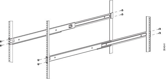
The distance between the outside face of the front mounting rail and the outside face of the back mounting rail should be 23.5 to 34.0 in. (59.7 to 86.4 cm) to allow for rear bracket installation.
-
There should be a minimum of 2.5 in. (6.4 cm) of clear space between the side edge of the chassis and the side wall of the cabinet. No sizeable flow obstructions should be immediately in the way of the chassis air intake or exhaust vents.
-
Note |
Optional jumper power cords are available for use in a cabinet. See the Jumper Power Cord section. |
Requirements Specific to Perforated Cabinets
-
The front and rear doors must have at least a 60 percent open area perforation pattern, with at least 15 sq. in. of open area per rack unit of door height.
-
We recommend that the roof be perforated with at least 20 percent open area, unless the cabinet only contains Cisco MDS 9396S switch, in which case the roof does not have to be perforated.
-
We recommend an open or perforated cabinet floor to enhance cooling but it is not required.
Reference Perforated Cabinet
Rittal Corporation
One Rittal Place
Springfield, OH 45504
Phone: (800) 477-4000
Cabinet P/N: Rittal 9969427
Cabinet description: PS-DK/OEM Cabinet Assembly, 1998 x 600 x 1000 (H x W x D) (42U)
Requirements Specific to Solid-Walled Cabinets
-
A roof-mounted fan tray and an air cooling scheme in which the fan tray pulls air in at the bottom of the cabinet and exhausts it out the top, with a minimum of 500 cfm of airflow exiting the cabinet roof through the fan tray.
-
Nonperforated (solid and sealed) front and back doors and side panels so that air travels predictably from bottom to top.
-
The overall cabinet depth should be 36 to 42 in. (91.4 to 106.7 cm) to allow the doors to close and adequate airflow.
-
A minimum of 150 sq. in. (968 sq. cm) of open area at the floor air intake of the cabinet.
-
The lowest piece of equipment should be installed a minimum of 1.75 in. (4.4 cm) above the floor openings to prevent blocking the floor intake.
Requirements Specific to Standard Open Racks
-
Width between two front mounting rails: minimum of 17.75 in. (45.1 cm)
-
Minimum vertical rack space per chassis: 1 rack unit (RU), equal to 1.75 in. (4.4 cm)
-
The distance between the outside face of the front mounting rail and the outside face of the back mounting rail should be 23.5 to 34.0 in. (59.7 to 86.4 cm) to allow for rear bracket installation.
-
The distance between the chassis air vents and any walls should be 2.5 in. (6.4 cm).
Requirements Specific to Telco Racks
-
The width of the rack between the two rack-mounting rails should be at least 17.75 in. (45.1 cm).
-
The distance between the chassis air vents and any walls should be 2.5 in. (6.4 cm).


 Feedback