Cisco MDS 9250i Switch Overview
This chapter describes the Cisco MDS 9250i Switch and includes these topics:
Introduction
The Cisco MDS 9250i Switch (DS-C9250I-K9) is an optimized platform for deploying high-performance SAN extension solutions, distributed intelligent fabric services, and cost-effective multiprotocol connectivity for both open systems and mainframe environments.
The Cisco MDS 9250i Switch is an ideal solution for local office and remote branch-office SANs and also in large-scale SANs operating the Cisco MDS 9700 and 9500 Series Multilayer director platforms.
The Cisco MDS 9250i Switch offers 40 autosensing 2-, 4-, 8-, and 16-Gbps line-rate Fibre Channel ports, eight 10-Gbps Ethernet Fibre Channel over Ethernet (FCoE) ports, and two 10-Gbps Ethernet IP storage services ports in a fixed two-rack-unit (2RU) form factor.
The Cisco MDS 9250i Switch can be deployed in the existing native Fibre Channel networks, which ensures protection of your investments in storage networks. Two 1/10-Gbps ports support Small Computer System Interface over IP (iSCSI) storage services. By using the eight 10-Gbps Ethernet FCoE ports, the Cisco MDS 9250i Switch can be attached to the directly connected FCoE and Fibre Channel storage devices. The Cisco MDS 9250i Switch supports multi-tiered unified network fabric connectivity directly over FCoE. The Cisco MDS 9250i Switch has front-to-back airflow and comes with a set of storage services for Fibre Channel and FCoE SANs with FCIP, IO accelerator (IOA), and data mobility migration (DMM).
The Cisco SAN Extension over IP application package license is enabled as standard on the two fixed 1/10 Gbps Ethernet IP storage services ports, enabling features such as Fibre Channel over IP (FCIP) and compression on the switch without additional licenses.
The Cisco MDS 9250i Switch supports the following:

Note![]() For information about achieving grid level redundancy, see Power Supplies.
For information about achieving grid level redundancy, see Power Supplies.
- Hot-swappable, 1+1 redundant fan tray with integrated temperature and power management
- Hot-swappable SFP+ optics
Figure 1-1 Cisco MDS 9250i Switch Front View
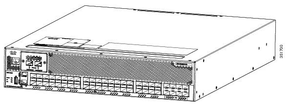
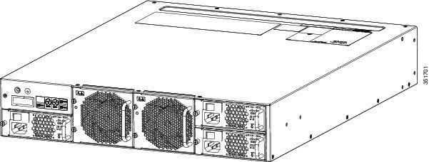
Figure 1-2 Cisco MDS 9250i Switch Rear View
Chassis Description
The Cisco MDS 9250i Switch has a nonremovable supervisor module with 40 integrated 16-Gbps FC ports and eight 10-Gbps Ethernet Fibre Channel over Ethernet (FCoE) ports.
The Cisco MDS 9250i Switch also has these additional modules:
- A 2 port 1/10-Gbps Ethernet IP storage services module
- USB port on the front panel for code uploads, configuration file backups, log dumps, and report capture
- A nonremovable interface module (located on the left side of the integrated supervisor module), which provides one RS-232 console port and one out of band management 10/100 Mbps Ethernet port
- Three power supplies that are redundant by default
Note![]() To obtain grid level redundancy, it is recommended that you use a dual power source ATS with the switch. For more information, see Power Supplies.
To obtain grid level redundancy, it is recommended that you use a dual power source ATS with the switch. For more information, see Power Supplies.
Cisco MDS 9250i Integrated Supervisor Module
The nonremovable Cisco MDS 9250i integrated supervisor module provides the control and management functions of the Cisco MDS 9250i Multiservice Fabric switch, and it includes 40 integrated 16-Gbps Fibre Channel switching ports and eight 10-Gbps Ethernet Fibre Channel over Ethernet (FCoE) port modules.
The Cisco MDS 9250i integrated supervisor module has a PowerPC 8572E processor. It also has an internal CompactFlash card that provides 4 GB of storage for software images. The NVRAM consists of a battery, a battery controller and 512 Kx16 SRAM. SRAM used to store event logs, core dumps that are required to be stored after a power cycles.
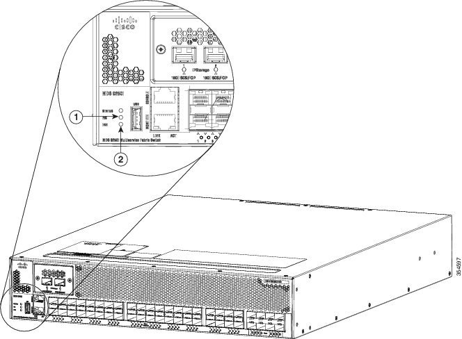
Front Panel LEDs
The front panel of the Cisco MDS 9250i Switch has the following LEDs:
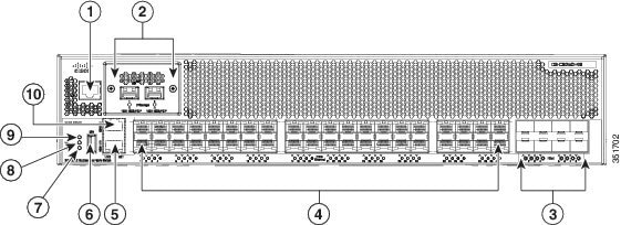
Figure 1-3 Cisco MDS 9250i Ports and LEDs
|
|
|
||
|
|
|
||
|
|
|
||
|
|
|
||
|
|
|
The LEDs on t he supervisor module indicate the status of the supervisor module, power supplies, and the system as a whole. Table 1-1 describes the LEDs.
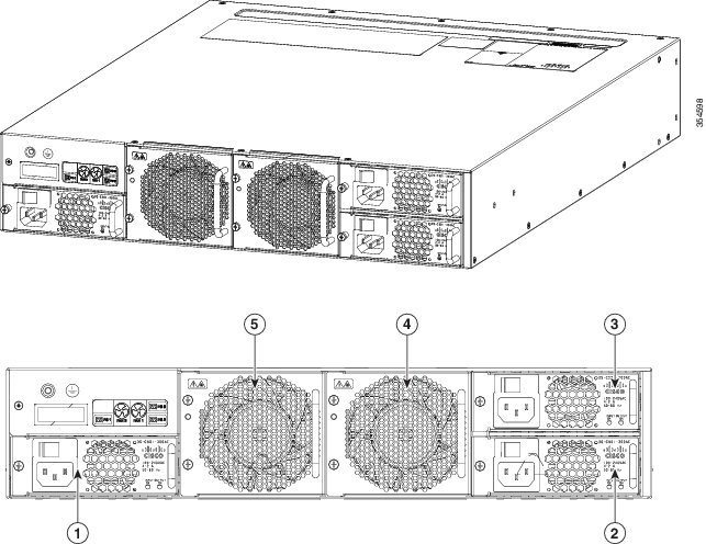
Table 1-2 Cisco MDS 9250i Switch Rear View Fan Bays and PSU Bays
|
|
|
||
|
|
|
||
|
|
|
Fan Modules
The Cisco MDS 9250i Switch has two fan trays that are installed vertically at the back of the chassis. Each fan module can be removed while the other fan module continues to move air through the chassis.
Figure 1-4 Cisco MDS 9250i Fan Module
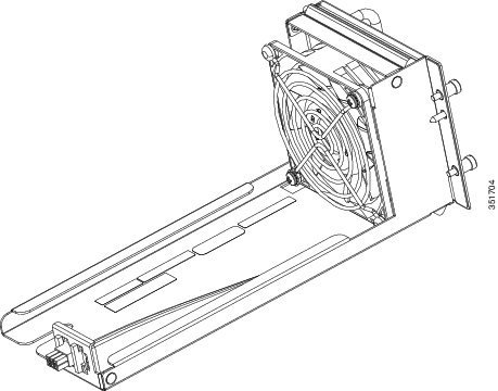
Figure 1-5 Cisco MDS 9250i Switch Front view LEDs
|
|
|
One fan can fail without affecting the thermal performance of the system. Redundant fan controllers and other internal mechanisms are in place to ensure that any single fan tray does not go down.
If any single fan fails, the system continues to operate under all conditions. Two fan failures might cause alarms from ASIC when the temperature exceeds the threshold. At 104°F (40°C) or less, a single fan tray can be removed and the system can continue to operate long enough to allow for replacement of a failed fabric module or fan tray.
Power Supplies
The Cisco MDS 9250i switch has capacity for up to three hot swappable 300 W AC power supply units (PSUs). Figure 1-6 illustrates the power supply unit.
Figure 1-6 Cisco MDS 9250i Switch 300 W AC Power Supply
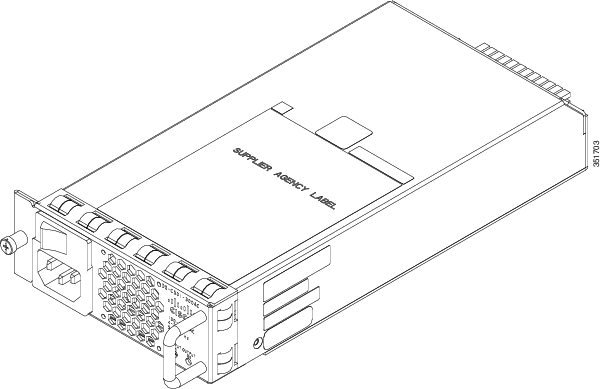
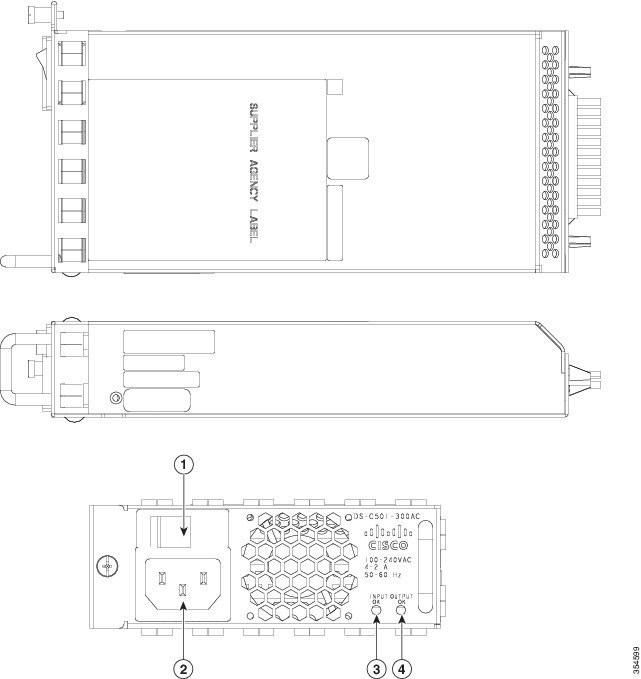
Figure 1-7 Cisco MDS 9250i Switch PSU
|
|
|
||
|
|
|
Each PSU can provide information about itself to the supervisor. The two types of information available are status information (output voltage, fan state, unit state) and part information (serial number and revision). When connected to nominal 110 or 220 VAC input each PSU provides 300 W of output power.
In the default configuration and with all three PSUs installed, the Cisco MDS 9250i switch has N+1 PSU redundancy. The only power redundancy mode available is redundant ; combined mode is not supported on this platform.
To obtain grid redundancy with the Cisco MDS 9250i switch an Automatic Transfer Switch (ATS) is required. An ATS is a third party power switch that connects to two power sources (usually different power grids) to provide uninterrupted power to downstream devices in the event of one of the sources failing. Connect one of the PSUs to the ATS and each of the other PSUs to separate grids. It is not necessary to connect all three PSUs to the ATS. This is illustrated in Figure 1-8.
Figure 1-8 Connecting an ATS for power grid level redundancy
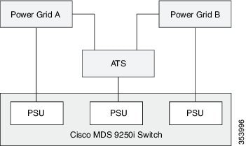
In this way the ATS is not a single point of failure. If it fails then the two PSUs directly connected to the grids supply enough power. Similarly, if one of the grids fails, two PSUs remain functional – one through the ATS and the other directly connected to the other grid.
The APC AP7721 has been verified to work with the Cisco MDS 9250i switch.
If insufficient power is available to the Cisco MDS 9250i switch the system will put the remaining PSUs in shutdown mode to prevent heat damage to them. A PSU in this mode can be identified by the green input LED and red output LED. To reset a PSU in this state the AC input must be removed for at least 2 seconds. This can be done by manually cycling the power switch of the PSU off and on over a 5 second interval.
Support for Power Redundancy with Two Online PSUs
All Cisco MDS NX-OS 6.2(x) Releases starting from Cisco MDS NX-OS Release 6.2(15) and all Cisco MDS NX-OS 7.3(x) Releases starting from Cisco MDS NX-OS Release 7.3(1)D1(1) support power redundancy with two online PSUs on the Cisco MDS 9250i Switch. To enable power redundancy in this scenario, FCoE ports must be brought to ADMIN DOWN state. The power supplies in a Cisco MDS 9250i Switch work in the following power modes when FcoE ports are in ADMIN DOWN state:
3 online PSUs—Two PSUs are connected to Grid A and one PSU is connected to Grid B; they work in N+1 redundant mode.
2 online PSUs—One PSU is connected to Grid A and another PSU is connected to Grid B; they work in N:N redundant mode.
1 online PSU—The PSU is connected to any one grid; it works in non-redundant mode.
The power supplies in a Cisco MDS 9250i Switch work in the following power modes when FCoE ports are in ADMIN UP state:
3 online PSUs—They work in N+1 redundant mode.
2 online PSUs—They work in non-redundant mode.
1 online PSU—It works in non-redundant mode. In this case, FCoE ports automatically switch to an
Supported Transceivers
The Cisco MDS 9250i Switch supports these transceivers:
- 8-Gbps SW/LW, LC Enhanced Small Form-Factor Pluggable (SFP+)
- 10-Gbps SW/LW, LC SFP+
- 10-GbE SR/LR/ER, LC, SFP+
- 16-Gbps SW/LW LC SFP+
- 4/8/16-Gbps Fibre Channel LW SFP+, DWDM, SM, DDM, 13 dB, 40 km
- 4/8/16-Gbps Fibre Channel LW SFP+, CWDM, SM, DDM, 13 dB, 40 km
- 4/8/16-Gbps Fibre Channel/FICON LW SFP+, DWDM, SM, DDM, 1550nm, 13 dB, 40 km
- 2/4/8-Gbps Fibre Channel LW SFP+, DWDM, SM, DDM, 80 km
- 2/4/8-Gbps Fibre Channel LW SFP+, CWDM, SM, DDM, 23dB, 70 km
- 2/4/8-Gbps Fibre Channel LW SFP+, SM, DDM, 80 km
Fibre Channel SFP+ Transceivers
The Fibre Channel SFP+ transceivers are field-replaceable and hot-swappable. You can use any combination of SFP+ transceivers that are supported by the switch. The only restrictions are that SWL transceivers must be paired with SWL transceivers, and LWL transceivers must be paired with LWL transceivers, and the cable must not exceed the stipulated cable length for reliable communications.
For more information about a specific Cisco SFP+ transceiver, see the “Technical Specifications”. SFP+ transceivers can be ordered separately or with the Cisco MDS 9250i Switch.
Note![]() Use only Cisco transceivers in the Cisco MDS 9250i Switch. Each Cisco transceiver is encoded with model information that enables the switch to verify that the transceiver meets the requirements for the switch.
Use only Cisco transceivers in the Cisco MDS 9250i Switch. Each Cisco transceiver is encoded with model information that enables the switch to verify that the transceiver meets the requirements for the switch.
 Feedback