About Routing Protocol Support
Routing within the Cisco ACI fabric is implemented using BGP (with BFD support) and the OSPF or EIGRP routing protocols.
IP source routing is not supported in the ACI fabric.
The documentation set for this product strives to use bias-free language. For the purposes of this documentation set, bias-free is defined as language that does not imply discrimination based on age, disability, gender, racial identity, ethnic identity, sexual orientation, socioeconomic status, and intersectionality. Exceptions may be present in the documentation due to language that is hardcoded in the user interfaces of the product software, language used based on RFP documentation, or language that is used by a referenced third-party product. Learn more about how Cisco is using Inclusive Language.
This chapter contains the following sections:
Routing within the Cisco ACI fabric is implemented using BGP (with BFD support) and the OSPF or EIGRP routing protocols.
IP source routing is not supported in the ACI fabric.
The following sections provide more information on BGP external routed networks with BFD support.
When configuring a BGP external routed network, follow these guidelines:
The BGP direct route export behavior changed after release 3.2(1), where ACI does not evaluate the originating route type (such as static, direct, and so on) when matching export route map clauses. As a result, the "match direct" deny clause that is always included in the outbound neighbor route map no longer matches direct routes, and direct routes are now advertised based on whether or not a user-defined route map clause matches.
Therefore, the direct route must be advertised explicitly through the route map. Failure to do so will implicitly deny the direct route being advertised.
The AS override option in the BGP Controls field in the BGP Peer Connectivity Profile for an L3Out was introduced in release 3.1(2). It allows Cisco Application Centric Infrastructure (ACI) to overwrite a remote AS in the AS_PATH with ACI BGP AS. In Cisco ACI, it is typically used when performing transit routing from an eBGP L3Out to another eBGP L3Out with the same AS number.
However, an issue arises if you enable the AS override option when the eBGP neighbor has a different AS number. In this situation, strip the peer-as from the AS_PATH when reflecting it to a peer.
The Local-AS Number option in the BGP Peer Connectivity Profile is supported only for eBGP peering. This enables Cisco ACI border leaf switches to appear to be a member of another AS in addition to its real AS assigned to the fabric MP-BGP Route Reflector Policy. This means that the local AS number must be different from the real AS number of the Cisco ACI fabric. When this feature is configured, Cisco ACI border leaf switches prepend the local AS number to the AS_PATH of the incoming updates and append the same to the AS_PATH of the outgoing updates. Prepending of the local AS number to the incoming updates can be disabled by the no-prepend setting in the Local-AS Number Config. The no-prepend + replace-as setting can be used to prevents the local AS number from being appended to the outgoing updates in addition to not prepending the same to the incoming updates.
A router ID for an L3Out for any routing protocols cannot be the same IP address or the same subnet as the L3Out interfaces such as routed interface, sub-interface or SVI. However, if needed, a router ID can be the same as one of the L3Out loopback IP addresses.
If you have multiple L3Outs of the same routing protocol on the same leaf switch in the same VRF instance, the router ID for those must be the same. If you need a loopback with the same IP address as the router ID, you can configure the loopback in only one of those L3Outs.
There are two ways to define the BGP peer for an L3Out:
Through the BGP peer connectivity profile (bgpPeerP) at the logical node profile level (l3extLNodeP), which associates the BGP peer to the loopback IP address. When the BGP peer is configured at this level, a loopback address is expected for BGP connectivity, so a fault is raised if the loopback address configuration is missing.
Through the BGP peer connectivity profile (bgpPeerP) at the logical interface profile level (l3extRsPathL3OutAtt), which associates the BGP peer to the respective interface or sub-interface.
It is recommended to use BGP default timers and leverage bidirectional forwarding detection (BFD) to get sub-second failure detection. Aggressive timers can cause BGP sessions to flap unexpectedly during CPU intense operations.
You must configure an IPv6 address to enable peering over loopback using IPv6.
Tenant networking protocol policies for BGP l3extOut connections can be configured with a maximum prefix limit that enables monitoring and restricting the number of route prefixes
received from a peer. After the maximum prefix limit is exceeded, a log entry can be recorded, further prefixes can be rejected,
the connection can be restarted if the count drops below the threshold in a fixed interval, or the connection is shut down.
You can use only one option at a time. The default setting is a limit of 20,000 prefixes, after which new prefixes are rejected.
When the reject option is deployed, BGP accepts one more prefix beyond the configured limit and the Cisco Application Policy Infrastructure
Controller (APIC) raises a fault.
 Note |
Cisco ACI does not support IP fragmentation. Therefore, when you configure Layer 3 Outside (L3Out) connections to external routers, or Multi-Pod connections through an Inter-Pod Network (IPN), it is recommended that the interface MTU is set appropriately on both ends of a link. On some platforms, such as Cisco ACI, Cisco NX-OS, and Cisco IOS, the configurable MTU value does not take into account the Ethernet headers (matching IP MTU, and excluding the 14-18 Ethernet header size), while other platforms, such as IOS-XR, include the Ethernet header in the configured MTU value. A configured value of 9000 results in a max IP packet size of 9000 bytes in Cisco ACI, Cisco NX-OS, and Cisco IOS, but results in a max IP packet size of 8986 bytes for an IOS-XR untagged interface. For the appropriate MTU values for each platform, see the relevant configuration guides. We highly recommend that you test the MTU using CLI-based commands. For example, on the Cisco NX-OS CLI, use a command such as |
The ACI supports the following BGP connection types and summarizes the loopback guidelines for them:
|
BGP Connection Type |
Loopback required |
Loopback same as Router ID |
Static/OSPF route required |
|---|---|---|---|
|
iBGP direct |
No |
Not applicable |
No |
|
iBGP loopback peering |
Yes, a separate loopback per L3Out |
No, if multiple Layer 3 out are on the same node |
Yes |
|
eBGP direct |
No |
Not applicable |
No |
|
eBGP loopback peering (multi-hop) |
Yes, a separate loopback per L3Out |
No, if multiple Layer 3 out are on the same node |
Yes |
Use the procedures in the following sections to configure BGP external routed networks.
The tenant, VRF, and bridge domain where you configure the BGP L3Out is already created, and you selected the Configure BGP Policies option when you were creating the VRF.
|
Step 1 |
In the Navigation pane, expand . |
|
Step 2 |
Right-click, and click Create L3Out. The Create L3Out wizard appears. |
|
Step 3 |
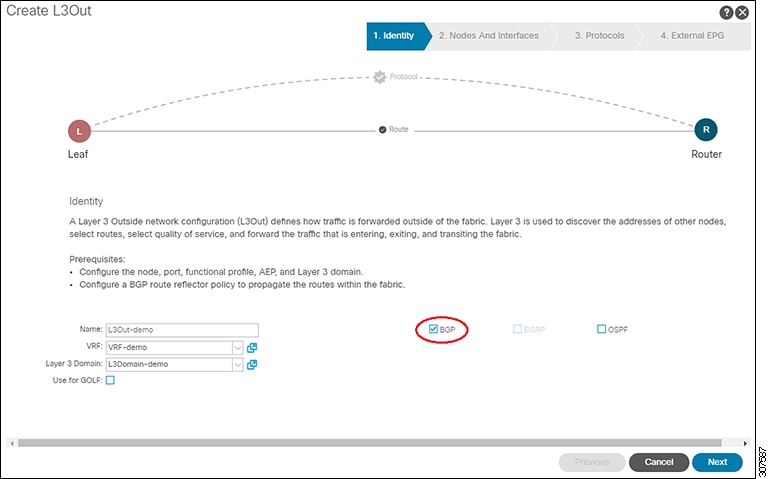
Enter the necessary information in the Identity window of the Create L3Out wizard. |
|
Step 4 |
Enter the necessary information in the Nodes and Interfaces window of the Create L3Out wizard. |
|
Step 5 |
Enter the necessary information in the Protocols window of the Create L3Out wizard. |
|
Step 6 |
Enter the necessary information in the External EPG window of the Create L3Out wizard. |
|
Step 7 |
(Optional) Navigate to the BGP Peer Connectivity Profile window to make additional configurations for the BGP external routed network, if necessary:
The BGP Peer Connectivity Profile for this L3Out appears. |
|
Step 8 |
Navigate to . |
|
Step 9 |
Click the Policy/Main tab and perform the following actions: |
|
Step 10 |
Navigate to . |
|
Step 11 |
Right-click Route map for import and export route control and select Create Route map for import and export route control. |
|
Step 12 |
Enter the necessary information in this window, then click + in the Context area to bring up the Create Route Control Context window. |
The following feature enables you to add the maximum number of paths to the route table to enable equal cost, multipath load balancing.
The appropriate tenant and the BGP external routed network are created and available.
|
Step 1 |
Log in to the APIC GUI, and on the menu bar, click and right click Create BGP Address Family Context Policy. |
|
Step 2 |
In the Create BGP Address Family Context Policy dialog box, perform the following tasks. Refer to the Verified Scalability Guide for Cisco APIC on the Cisco APIC documentation page for the acceptable values for the following fields.
|
|
Step 3 |
Click |
|
Step 4 |
Review the configuration details of the subject VRF. |
|
Step 5 |
Locate the BGP Context Per Address Family field and, in the BGP Address Family Type area, select either IPv4 unicast address family or IPv6 unicast address family. |
|
Step 6 |
Access the BGP Address Family Context you created in the BGP Address Family Context drop-down list and associate it with the subject VRF. |
|
Step 7 |
Click Submit. |
Use the procedures in the following sections to configure AS Path Prepend.
A BGP peer can influence the best-path selection by a remote peer by increasing the length of the AS-Path attribute. AS-Path Prepend provides a mechanism that can be used to increase the length of the AS-Path attribute by prepending a specified number of AS numbers to it.
AS-Path prepending can only be applied in the outbound direction using route-maps. AS Path prepending does not work in iBGP sessions.
The AS Path Prepend feature enables modification as follows:
| Prepend | Appends the specified AS number to the AS path of the route matched by the route map.
|
||
| Prepend-last-as | Prepends the last AS numbers to the AS path with a range between 1 and 10. |
The following table describes the selection criteria for implementation of AS Path Prepend:
| Prepend | 1 | Prepend the specified AS number. |
| Prepend-last-as | 2 | Prepend the last AS numbers to the AS path. |
| DEFAULT | Prepend(1) | Prepend the specified AS number. |
A configured tenant.
|
Step 1 |
Log in to the APIC GUI, and on the menu bar, click and right click Create Set Rules for a Route Map. The Create Set Rules For A Route Map window appears. |
|
Step 2 |
In the Create Set Rules For A Route Map dialog box, perform the following tasks:
|
|
Step 3 |
Select the criterion Prepend AS, then click + to prepend AS numbers. |
|
Step 4 |
Enter the AS number and its order and then click Update. Repeat by clicking + again if multiple AS numbers must be prepended. |
|
Step 5 |
When you have completed the prepend AS number configurations, select the criterion Prepend Last-AS to prepend the last AS number a specified number of times. |
|
Step 6 |
Enter Count (1-10). |
|
Step 7 |
Click OK. |
|
Step 8 |
In the Create Set Rules For A Route Map window, confirm the listed criteria for the set rule based on AS Path and click Finish. |
|
Step 9 |
On the APIC GUI menu bar, click and right click your profile. |
|
Step 10 |
Confirm the Set AS Path values the bottom of the screen. |
Use the procedures in the following sections to configure BGB external routed networks with AS override.
Loop prevention in BGP is done by verifying the Autonomous System number in the Autonomous System Path. If the receiving router sees its own Autonomous System number in the Autonomous System path of the received BGP packet, the packet is dropped. The receiving router assumes that the packet originated from its own Autonomous System and has reached the same place from where it originated initially. This setting is the default to prevent route loops from occurring.
The default setting to prevent route loops from occurring could create an issue if you use the same Autonomous System number along various sites and disallow user sites with identical Autonomous System numbers to link by another Autonomous System number. In such a scenario, routing updates from one site is dropped when the other site receives them.
To prevent such a situation from occurring, beginning with the Cisco APIC Release 3.1(2m), you can now enable the BGP Autonomous System override feature to override the default setting. You must also enable the Disable Peer AS Check at the same time.
The Autonomous System override function replaces the Autonomous System number from the originating router with the Autonomous System number of the sending BGP router in the AS Path of the outbound routes. This feature can be enabled per feature per address family (IPv4 or IPv6).
The Autonomous System Override feature is supported with GOLF Layer 3 configurations and Non-GOLF Layer 3 configurations.
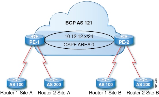
Router 1 and Router 2 are the two customers with multiple sites (Site-A and Site-B). Customer Router 1 operates under AS 100 and customer Router 2 operates under AS 200.
The above diagram illustrates the Autonomous System (AS) override process as follows:
Router 1-Site-A advertises route 10.3.3.3 with AS100.
Router PE-1 propagates this as an internal route to PE2 as AS100.
Router PE-2 prepends 10.3.3.3 with AS121 (replaces 100 in the AS path with 121), and propagates the prefix.
Router 2-Site-B accepts the 10.3.3.3 update.
The Tenant, VRF, Bridge Domain are created.
The External Routed Network that is in a non-GOLF setting, a logical node profile, and the BGP peer connectivity profile are created.
|
Step 1 |
On the menu bar, choose . |
|
Step 2 |
In the Navigation pane, choose the appropriate BGP Peer Connectivity Profile. |
|
Step 3 |
In the Work pane, under Properties for the BGP Peer Connectivity Profile, in the BGP Controls field, perform the following actions: |
|
Step 4 |
Click Submit. |
Use the procedures in the following sections to configure BGB neighbor shutdown and soft reset.
Beginning with Release 4.2(1), support is now available for the following features:
The BGP neighbor shutdown feature is similar to the neighbor shutdown command in NX-OS, which shuts down the corresponding BGP neighbor. Use this policy to disable and enable the BGP neighbor's admin state. Using this feature shuts down the BGP sessions without the need to delete the BGP peer configuration.
Using the BGP route refresh capability, the BGP neighbor soft reset feature provides automatic support for a dynamic soft reset of inbound and outbound BGP routing table updates that are not dependent upon stored routing table update information. Use this policy to enable the soft dynamic inbound reset and soft outbound reset.
The following procedure describes how to use the BGP neighbor shutdown feature using the GUI.
Complete the standard prerequisites before configuring an L3Out, such as:
Configure the node, port, functional profile, AEP, and Layer 3 domain.
Configure a BGP Route Reflector policy to propagate the routes within the fabric.
|
Step 1 |
Create the L3Out and configure the BGP for the L3Out:
|
|
Step 2 |
After you have completed the L3Out configuration, configure the BGP neighbor shutdown: |
The following procedure describes how to use the BGP neighbor soft reset feature using the GUI.
Complete the standard prerequisites before configuring an L3Out, such as:
Configure the node, port, functional profile, AEP, and Layer 3 domain.
Configure a BGP Route Reflector policy to propagate the routes within the fabric.
|
Step 1 |
Create the L3Out and configure the BGP for the L3Out:
|
|
Step 2 |
After you have completed the L3Out configuration, configure the BGP neighbor soft reset: |
Use the procedures in the following sections to configure per VRF per node BGP timer values.
Prior to the introduction of this feature, for a given VRF, all nodes used the same BGP timer values.
With the introduction of the per VRF per node BGP timer values feature, BGP timers can be defined and associated on a per
VRF per node basis. A node can have multiple VRFs, each corresponding to a fvCtx. A node configuration (l3extLNodeP) can now contain configuration for BGP Protocol Profile (bgpProtP) which in turn refers to the desired BGP Context Policy (bgpCtxPol). This makes it possible to have a different node within the same VRF contain different BGP timer values.
For each VRF, a node has a bgpDom concrete MO. Its name (primary key) is the VRF, <fvTenant>:<fvCtx>. It contains the BGP timer values as attributes (for example, holdIntvl, kaIntvl, maxAsLimit).
All the steps necessary to create a valid Layer 3 Out configuration are required to successfully apply a per VRF per node
BGP timer. For example, MOs such as the following are required: fvTenant, fvCtx, l3extOut, l3extInstP, LNodeP, bgpRR.
On a node, the BGP timer policy is chosen based on the following algorithm:
If bgpProtP is specified, then use bgpCtxPol referred to under bgpProtP.
Else, if specified, use bgpCtxPol referred to under corresponding fvCtx.
Else, if specified, use the default policy under the tenant, for example, uni/tn-<tenant>/bgpCtxP-default.
Else, use the default policy under tenant common, for example, uni/tn-common/bgpCtxP-default. This one is pre-programmed.
|
Step 1 |
On the menu bar, choose , then right click Create BGP Timers Policy. |
||
|
Step 2 |
In the Create BGP Timers Policy dialog box, perform the following actions:
|
||
|
Step 3 |
Navigate to , and right-click Create L3Out. The Create L3Out wizard appears. Create an L3Out with BGP enabled by performing the following actions. |
||
|
Step 4 |
Enter the necessary information in the Identity window of the Create L3Out wizard.
|
||
|
Step 5 |
After you have created the L3Out, navigate to the logical node profile in the L3Out that you just created: . |
||
|
Step 6 |
In the Logical Node Profile window, check next to Create BGP Protocol Profile. |
||
|
Step 7 |
In the BGP Timers field, from the drop-down list, choose the BGP timer policy that you want to associate with this specific node. Click Submit. A specific BGP timer policy is now applied to the node.
|
||
|
Step 8 |
To verify the configuration, in the Navigation pane, perform the following steps:
|
The following inconsistencies or faults could occur under certain conditions:
l3Out) are associated with the same VRF (fvCtx), and on the same node, the bgpProtP is associated with different policies (bgpCtxPol), a fault will be raised. In the case of the example below, both Layer 3 Outs (out1 and out2) are associated with the same VRF (ctx1). Under out1, node1 is associated with the BGP timer protocol pol1 and under out2, node1 is associated with a different BGP timer protocol pol2. This will raise a fault.
tn1
  ctx1
  out1
    ctx1
    node1
      protp pol1

  out2
    ctx1
    node1
      protp pol2
If such a fault is raised, change the configuration to remove the conflict between the BGP timer policies.
Use the procedures in the following sections to configure BFD support.
Use Bidirectional Forwarding Detection (BFD) to provide sub-second failure detection times in the forwarding path between ACI fabric border leaf switches configured to support peering router connections.
BFD is particularly useful in the following scenarios:
When the peering routers are connected through a Layer 2 device or a Layer 2 cloud where the routers are not directly connected to each other. Failures in the forwarding path may not be visible to the peer routers. The only mechanism available to control protocols is the hello timeout, which can take tens of seconds or even minutes to time out. BFD provides sub-second failure detection times.
When the peering routers are connected through a physical media that does not support reliable failure detection, such as shared Ethernet. In this case too, routing protocols have only their large hello timers to fall back on.
When many protocols are running between a pair of routers, each protocol has its own hello mechanism for detecting link failures, with its own timeouts. BFD provides a uniform timeout for all the protocols, which makes convergence time consistent and predictable.
Observe the following BFD guidelines and limitations:
Prior to APIC release 5.0, BFD echo packets received on a leaf switch from neighbor routers are classified with the default QoS class (best effort). Due to that classification, BFD drops might result when there is congestion on the interfaces.
Starting from APIC release 3.1(1), BFD between leaf and spine switches is supported on fabric-interfaces for IS-IS. In addition, BFD feature on spine switch is supported for OSPF and static routes.
BFD is supported on modular spine switches that have -EX and -FX line cards (or newer versions), and BFD is also supported on the Nexus 9364C non-modular spine switch (or newer versions).
BFD between VPC peers is not supported.
Multihop BFD is not supported.
BFD over iBGP is not supported for loopback address peers.
BFD sub interface optimization can be enabled in an interface policy. One sub-interface having this flag will enable optimization for all the sub-interfaces on that physical interface.
BFD for BGP prefix peer not supported.
Note |
Cisco ACI does not support IP fragmentation. Therefore, when you configure Layer 3 Outside (L3Out) connections to external routers, or Multi-Pod connections through an Inter-Pod Network (IPN), it is recommended that the interface MTU is set appropriately on both ends of a link. On some platforms, such as Cisco ACI, Cisco NX-OS, and Cisco IOS, the configurable MTU value does not take into account the Ethernet headers (matching IP MTU, and excluding the 14-18 Ethernet header size), while other platforms, such as IOS-XR, include the Ethernet header in the configured MTU value. A configured value of 9000 results in a max IP packet size of 9000 bytes in Cisco ACI, Cisco NX-OS, and Cisco IOS, but results in a max IP packet size of 8986 bytes for an IOS-XR untagged interface. For the appropriate MTU values for each platform, see the relevant configuration guides. We highly recommend that you test the MTU using CLI-based commands. For example, on the Cisco NX-OS CLI, use a command such as |
|
Step 1 |
On the menu bar, choose . |
||
|
Step 2 |
In the Navigation pane, expand the .
For each of these BFD configurations, you can choose to use the default policy or create a new one for a specific switch (or set of switches).
|
||
|
Step 3 |
To create a switch profile for a specific global BFD policy (which is not the default), in the Navigation pane, expand the . |
||
|
Step 4 |
On the right side of the Work pane, under ACTIONS, select Create Leaf Profile. |
||
|
Step 5 |
In the Create Leaf Profile dialog box, perform the following actions: |
||
|
Step 6 |
In the Create Access Switch Policy Group dialog box, perform the following actions:
|
||
|
Step 7 |
Click SUBMIT. |
||
|
Step 8 |
To view the BFD global configuration you created, in the Navigation pane, expand the . |
|
Step 1 |
On the menu bar, choose . |
||
|
Step 2 |
In the Navigation pane, expand the .
For each of these BFD configurations, you can choose to use the default policy or create a new one for a specific switch (or set of switches).
|
||
|
Step 3 |
To create a spine switch profile for a specific global BFD policy (which is not the default), in the Navigation pane, expand the . |
||
|
Step 4 |
On the right side of the Work pane, under ACTIONS, select Create Spine Profile. |
||
|
Step 5 |
In the Create Spine Profile dialog box, perform the following actions: |
||
|
Step 6 |
In the Create Spine Switch Policy Group dialog box, perform the following actions:
|
||
|
Step 7 |
Click SUBMIT. |
||
|
Step 8 |
To view the BFD global configuration you created, in the Navigation pane, expand the . |
There are three supported interfaces (routed Layer 3 interfaces, the external SVI interface, and the routed sub-interfaces) on which you can configure an explicit bi-directional forwarding detection (BFD) configuration. If you don't want to use the global configuration, yet you want to have an explicit configuration on a given interface, you can create your own global configuration, which gets applied to all the interfaces on a specific switch or set of switches. This interface override configuration should be used if you want more granularity on a specific switch on a specific interface.
Note |
When a BFD interface policy is configured over a parent routed interface, by default all of its routed sub-interfaces with the same address family as that of the parent interface will inherit this policy. If any of the inherited configuration needs to be overridden, configure an explicit BFD interface policy on the sub-interfaces. However, if Admin State or Echo Admin State is disabled on the parent interface, the property cannot be overridden on the sub-interfaces. |
A tenant has already been created.
|
Step 1 |
On the menu bar, choose . |
|
Step 2 |
In the Navigation pane (under Quick Start), expand the Tenant you created . |
|
Step 3 |
Right-click on L3Outs and select Create L3Out. |
|
Step 4 |
Enter the necessary information in the Identity window of the Create L3Out wizard.
|
|
Step 5 |
Enter the necessary information in the Nodes and Interfaces window of the Create L3Out wizard. |
|
Step 6 |
Enter the necessary information in the Protocols window of the Create L3Out wizard. |
|
Step 7 |
Enter the necessary information in the External EPG window of the Create L3Out wizard. |
|
Step 8 |
Navigate to |
|
Step 9 |
In the Logical Interface Profile window, scroll down to the Create BFD Interface Profile field, then check the box next to this field. |
|
Step 10 |
In the Create BFD Interface Profile window, enter BFD details.
|
|
Step 11 |
Click SUBMIT. |
|
Step 12 |
To see the configured interface level BFD policy, navigate to . |
This procedure provides the steps to enable bi-directional forwarding detection (BFD) in the consumer protocols (OSPF, BGP, EIGRP, Static Routes, and IS-IS), which are consumers of the BFD feature. To consume the BFD on these protocols, you must enable a flag in them.
Note |
These four consumer protocols are located in the left navigation pane under . |
A tenant has already been created.
|
Step 1 |
Create an L3Out using the Create L3Out wizard. |
||
|
Step 2 |
On the menu bar, choose . |
||
|
Step 3 |
To configure BFD in the BGP protocol, in the Navigation pane (under Quick Start), expand the Tenant you created . |
||
|
Step 4 |
On the right side of the Work pane, under ACTIONS, select Create BGP Peer Prefix Policy.
|
||
|
Step 5 |
Enter a name in the Name field and provide values in the remaining fields to define the BGP peer prefix policy. |
||
|
Step 6 |
Click Submit. |
||
|
Step 7 |
Navigate to . |
||
|
Step 8 |
In the BGP Peer Connectivity Profile window, scroll down to the BGP Peer Prefix Policy field and select the BGP peer prefix policy that you just created. |
||
|
Step 9 |
In the Peer Controls field, select Bidirectional Forwarding Detection to enable BFD on the BGP consumer protocol (or uncheck the box to disable BFD). |
||
|
Step 10 |
To configure BFD in the OSPF protocol, in the Navigation pane, go to . |
||
|
Step 11 |
On the right side of the Work pane, under ACTIONS, select Create OSPF Interface Policy.
|
||
|
Step 12 |
Enter a name in the Name field and provide values in the remaining fields to define the OSPF interface policy. |
||
|
Step 13 |
In the Interface Controls section of this dialog box, you can enable or disable BFD. To enable it, check the box next to BFD, which adds a flag to the OSPF consumer protocol, shown as follows (or uncheck the box to disable BFD). |
||
|
Step 14 |
Click Submit. |
||
|
Step 15 |
To configure BFD in the EIGRP protocol, in the Navigation pane, go back to . |
||
|
Step 16 |
On the right side of the Work pane, under ACTIONS, select Create EIGRP Interface Policy.
|
||
|
Step 17 |
Enter a name in the Name field and provide values in the remaining fields to define the OSPF interface policy. |
||
|
Step 18 |
In the Control State section of this dialog box, you can enable or disable BFD. To enable it, check the box next to BFD, which adds a flag to the EIGRP consumer protocol (or uncheck the box to disable BFD). |
||
|
Step 19 |
Click Submit. |
||
|
Step 20 |
To configure BFD in the Static Routes protocol, in the Navigation pane, go back to , then click on the configured node to bring up the Node Association window. |
||
|
Step 21 |
In the Static Routes section, click the "+" (expand) button. |
||
|
Step 22 |
Next to Route Control, check the box next to BFD to enable (or uncheck the box to disable) BFD on the specified Static Route. |
||
|
Step 23 |
Click Submit. |
||
|
Step 24 |
To configure BFD in the IS-IS protocol, in the Navigation pane go to . |
||
|
Step 25 |
On the right side of the Work pane, under ACTIONS, select Create L3 Interface Policy.
|
||
|
Step 26 |
Enter a name in the Name field and provide values in the remaining fields to define the L3 interface policy. |
||
|
Step 27 |
To enable BFD ISIS Policy, in the BFD ISIS Policy Configuration field, click enabled. |
||
|
Step 28 |
Click Submit. |
Use the procedures in the following sections to configure OSPF external routed networks.
OSPF Layer 3 Outside connections can be normal or NSSA areas. The backbone (area 0) area is also supported as an OSPF Layer 3 Outside connection area. Cisco Application Centric Infrastructure (ACI) supports both OSPFv2 for IPv4 and OSPFv3 for IPv6. When creating an OSPF Layer 3 Outside, it is not necessary to configure the OSPF version. The correct OSPF process is created automatically based on the interface profile configuration (IPv4 or IPv6 addressing). Both IPv4 and IPv6 protocols are supported on the same interface (dual stack) but it is necessary to create two separate interface profiles.
Layer 3 Outside connections are supported for the routed interfaces, routed sub-interfaces, and SVIs. The SVIs are used when there is a need to share the physical connect for both Layer 2 and Layer 3 traffic. The SVIs are supported on ports, port channels, and virtual port channels.
When an SVI is used for a Layer 3 Outside connection, an external bridge domain is created on the border leaf switches. The external bridge domain allows connectivity between the two vPC switches across the Cisco ACI fabric. This allows both the vPC switches to establish the OSPF adjacencies with each other and the external OSPF device.
When running OSPF over a broadcast network, the time to detect a failed neighbor is the dead time interval (default 40 seconds). Reestablishing the neighbor adjacencies after a failure may also take longer due to designated router (DR) election.
Note |
|
You must verify that the router ID and the logical interface profile IP address are different and do not overlap.
The following steps are for creating an OSPF L3Out for a management tenant. To create an OSPF L3Out for a tenant, you must choose a tenant and create a VRF for the tenant.
For more details, see Cisco APIC and Transit Routing.
|
Step 1 |
On the menu bar, choose . |
|
Step 2 |
In the Navigation pane, expand . |
|
Step 3 |
Right-click L3Outs, and click Create L3Out. The Create L3Out wizard appears. |
|
Step 4 |
In the Identity window in the Create L3Out wizard, perform the following actions: |
|
Step 5 |
In the Nodes and Interfaces window, perform the following actions: |
|
Step 6 |
In the Protocols window, in the Policy area, click default, then click Next. The External EPG window appears. |
|
Step 7 |
In the External EPG window, perform the following actions: |
Use the procedures in the following sections to configure EIGRP external routed networks.
This example shows how to configure Enhanced Interior Gateway Routing Protocol (EIGRP) when using the Cisco APIC. The following information applies when configuring EIGRP:
The tenant, VRF, and bridge domain must already be created.
The Layer 3 outside tenant network must already be configured.
The route control profile under routed outside must already be configured.
The EIGRP VRF policy is the same as the EIGRP family context policy.
EIGRP supports only export route control profile. The configuration related to route controls is common across all the protocols.
You can configure EIGRP to perform automatic summarization of subnet routes (route summarization) into network-level routes. For example, you can configure subnet 131.108.1.0 to be advertised as 131.108.0.0 over interfaces that have subnets of 192.31.7.0 configured. Automatic summarization is performed when there are two or more network router configuration commands configured for the EIGRP process. By default, this feature is enabled. For more information, see Route Summarization.
EIGRP protocol is modeled similar to other routing protocols in the Cisco Application Centric Infrastructure (ACI) fabric.
The following features are supported:
IPv4 and IPv6 routing
Virtual routing and forwarding (VRF) and interface controls for each address family
Redistribution with OSPF across nodes
Default route leak policy per VRF
Passive interface and split horizon support
Route map control for setting tag for exported routes
Bandwidth and delay configuration options in an EIGRP interface policy
Authentication support
The following features are not supported:
Stub routing
EIGRP used for BGP connectivity
Multiple EIGRP L3extOuts on the same node
Per-interface summarization (an EIGRP summary policy will apply to all interfaces configured under an L3Out)
Per interface distribute lists for import and export
EIGRP functions can be broadly categorized as follows:
Protocol policies
L3extOut configurations
Interface configurations
Route map support
Default route support
Transit support
The following primary managed objects provide EIGRP support:
EIGRP Address Family Context Policy eigrpCtxAfPol: Address Family Context policy configured under fvTenant (Tenant/Protocols).
fvRsCtxToEigrpCtxAfPol: Relation from a VRF to a eigrpCtxAfPol for a given address family (IPv4 or IPv6). There can be only one relation for each address family.
eigrpIfPol: EIGRP Interface policy configured in fvTenant.
eigrpExtP: Enable flag for EIGRP in an L3extOut.
eigrpIfP: EIGRP interface profile attached to an l3extLIfP.
eigrpRsIfPol: Relation from EIGRP interface profile to an eigrpIfPol.
Defrtleak: Default route leak policy under an l3extOut.
The following EIGRP protocol policies are supported under a tenant:
EIGRP Interface policy (eigrpIfPol)—contains the configuration that is applied for a given address family on an interface. The following configurations are
allowed in the interface policy:
Hello interval in seconds
Hold interval in seconds
One or more of the following interface control flags:
split horizon
passive
next hop self
EIGRP Address Family Context Policy
(eigrpCtxAfPol)—contains the configuration for a given address family in a given VRF. An eigrpCtxAfPol is configured under tenant protocol policies and can be applied to one or more VRFs under the tenant. An eigrpCtxAfPol can be enabled on a VRF through a relation in the VRF-per-address family. If there is no relation to a given address family,
or the specified eigrpCtxAfPol in the relation does not exist, then the default VRF policy created under the common tenant is used for that address family.
The following configurations are allowed in the eigrpCtxAfPol:
Administrative distance for internal route
Administrative distance for external route
Maximum ECMP paths allowed
Active timer interval
Metric version (32-bit / 64-bit metrics)
When configuring EIGRP, follow these guidelines:
Configuring EIGRP and BGP for the same Layer 3 outside is not supported.
Configuring EIGRP and OSPF for the same Layer 3 outside is not supported.
There can be one EIGRP Layer 3 Out per node per VRF. If multiple VRFs are deployed on a node, each VRF can have its own Layer 3 Out.
Multiple EIGRP peers from a single Layer 3 Out is supported. This enables you to connect to multiple EIGRP devices from the same node with a single Layer 3 Out.
The following configurations will cause the EIGRP neighbors to flap:
Changing administrative distances or metric style (wide/narrow) through an EIGRP address family context in the VRF
Setting configurations of multiple EIGRP summary routes to external EPG all at once. In contrast, configuring only a single EIGRP summary route will not cause the EIGRP neighbors to flap.
Setting the following configurations that will cause a table-map used internally to be updated:
Changing the route tag for the VRF
Setting configurations of import direction route control for an OSPF L3Out in the same VRF on the same border leaf switch as an EIGRP L3Out (for example, enabling or disabling the Route Control Enforcement “Import” option or changing routes that are allowed or denied for the import direction). Note that such configurations are not allowed in an EIGRP L3Out itself as the feature is not supported for EIGRP. However, the configurations in an OSPF L3Out still impacts EIGRP L3Outs in the same VRF and leaf switch. This is because the import route control for OSPF utilizes a table-map that is shared, for other purposes, with EIGRP in the same VRF on the same border leaf switch.
|
Step 1 |
On the menu bar, choose . |
||
|
Step 2 |
In the Work pane, double click a tenant. |
||
|
Step 3 |
In the Navigation pane, expand the . |
||
|
Step 4 |
Right-click EIGRP Address Family Context and choose Create EIGRP Address Family Context Policy. |
||
|
Step 5 |
In the Create EIGRP Address Family Context Policy dialog box, perform the following actions:
|
||
|
Step 6 |
To apply the context policy on a VRF, in the Navigation pane, expand . |
||
|
Step 7 |
Choose the appropriate VRF, and in the Work pane under the Policy tab, expand EIGRP Context Per Address Family. |
||
|
Step 8 |
In the EIGRP Address Family Type drop-down list, choose an IP version. |
||
|
Step 9 |
In the EIGRP Address Family Context drop-down list, choose the context policy. Click Update, and Click Submit. |
||
|
Step 10 |
To enable EIGRP within the Layer 3 Out, in the Navigation pane, click , and click the desired Layer 3 outside network. |
||
|
Step 11 |
In the Work pane under the Policy tab, check the checkbox for EIGRP, and enter the EIGRP Autonomous System number. Click Submit. |
||
|
Step 12 |
To create an EIGRP interface policy, in the Navigation pane, click and perform the following actions:
|
||
|
Step 13 |
In the Navigation pane, click the appropriate external routed network where EIGRP was enabled, expand Logical Node Profiles and perform the following actions:
|
 Feedback