Layer 3 Routed and Sub-Interface Port Channels

About Layer 3 Port Channels

Previously, Cisco APIC supported only Layer 2 port channels. Starting with release 3.2(1), Cisco APIC now supports Layer 3 port channels.
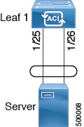
Figure 1. Switch Port Channel Configuration


Note


Layer 3 routed and sub-interface port channels on border leaf switches are supported only on new generation switches, which are switch models with "EX", "FX" or "FX2" at the end of the switch name.


Configuring Port Channels Using the GUI

You must first configure port channels using these procedures before you can configure a Layer 3 route to the port channels in subsequent procedures.

The procedure below uses a Quick Start wizard.

Before you begin


Note


The procedures in this section are meant specifically for configuring port channels as a prerequisite to the procedures for configuring a Layer 3 routed or subinterface port channel. For general instructions on configuring leaf switch port channels, refer to the Cisco APIC Basic Configuration Guide.


  • The ACI fabric is installed, APIC controllers are online, and the APIC cluster is formed and healthy.

  • An APIC fabric administrator account is available that enables creating the necessary fabric infrastructure configurations.

  • The target leaf switches are registered in the ACI fabric and available.

Procedure


Step 1

On the APIC menu bar, navigate to Fabric > Access Policies > Quick Start, and click Configure an interface, PC, and VPC.

Step 2

In the Configure Interface, PC, and VPC work area, click the large + to select switches to configure.

Step 3

In the Switches section, select a switch ID from the drop-down list of available switch IDs.

Step 4

Click the large + to configure switch interfaces.

Step 5

In the Interface Type field, specify PC as the interface type to use.

Step 6

In the Interfaces field, specify the interface IDs to use.

Step 7

(Optional) In the Interface Selector Name field, enter a unique interface selector name, if desired.

Step 8

In the Interface Policy Group area, specify the interface policies to use. For example, click the Port Channel Policy drop-down arrow to choose an existing port channel policy or to create a new port channel policy.

Note

 
  • Choosing to create a port channel policy displays the Create Port Channel Policy dialog box where you can specify the policy details and enable features such as symmetric hashing. Also note that choosing the Symmetric hashing option displays the Load Balance Hashing field, which enables you to configure hash tuple. However, only one customized hashing option can be applied on the same leaf switch.

  • Symmetric hashing is not supported on the following switches:

    • Cisco Nexus 93128TX

    • Cisco Nexus 9372PX

    • Cisco Nexus 9372PX-E

    • Cisco Nexus 9372TX

    • Cisco Nexus 9372TX-E

    • Cisco Nexus 9396PX

    • Cisco Nexus 9396TX

Step 9

In the Attached Device Type field, select the External Routed Devices option.

Step 10

In the Domain field, create a domain or choose one to assign to the interface.

Step 11

If you choose to create a domain, in the VLAN field, select from existing VLAN pools or create a new VLAN range to assign to the interface.

Step 12

Click Save to update the policy details, then click Submit to submit the switch profile to the APIC.

The APIC creates the switch profile, along with the interface, selector, and attached device type policies.

What to do next

Configure a Layer 3 routed port channel or a Layer 3 subinterface port channel using the GUI.

Configuring a Layer 3 Routed Port-Channel Using the GUI

This procedure configures a Layer 3 route to the port channels that you created previously.

Before you begin

  • The Cisco ACI fabric is installed, the Cisco APICs are online, and the Cisco APIC cluster is formed and healthy.

  • A Cisco APIC fabric administrator account is available that enables creating the necessary fabric infrastructure configurations.

  • The target leaf switches are registered in the Cisco ACI fabric and available.

  • Port channels are configured when port channels are used for L3Out interfaces.

Procedure


Step 1

On the menu bar, choose Tenants > All Tenants.

Step 2

In the Work pane, double click the tenant's name.

Step 3

In the Navigation pane, expand tenant_name > Networking > L3Outs > L3Out > Logical Node Profiles > node_profile > Logical Interface Profiles.

Step 4

Select the interface that you want to configure. The Logical Interface Profile page for that interface opens.

Step 5

Click on Routed Interfaces. The Properties page opens.

Step 6

Click on the Create (+) button to configure the Layer 3 routed port-channel. The Select Routed Interface page opens.

Step 7

In the Path Type field, select Direct Port Channel.

Step 8

In the Path field, select the port channel that you created previously from the drop-down list. This is the path to the port channel end points for the interface profile.

Step 9

In the Description field, enter a description of the routed interface.

Step 10

In the IPv4 Primary / IPv6 Preferred Address field, enter the primary IP addresses of the path attached to the Layer 3 outside profile.

Step 11

In the IPv6 DAD field, select disabled or enabled.

See "Configuring IPv6 Neighbor Discovery Duplicate Address Detection" for more information for this field.

Step 12

In the IPv4 Secondary / IPv6 Additional Addresses field, enter the secondary IP addresses of the path attached to the Layer 3 outside profile.

See "Configuring IPv6 Neighbor Discovery Duplicate Address Detection" for more information for the IPv6 DAD field in the Create Secondary IP Address screen.

Step 13

Check the ND RA Prefix box if you wish to enable a Neighbor Discovery Router Advertisement prefix for the interface. The ND RA Prefix Policy option appears.

When this is enabled, the routed interface is available for autoconfiguration and the prefix is sent to the host for autoconfiguration.

While ND RA Interface policies are deployed under bridge domains or Layer 3 Outs, ND prefix policies are deployed for individual subnets. The ND prefix policy is on a subnet level.

The ND RA Prefix applies only to IPv6 addresses.

Step 14

If you checked the ND RA Prefix box, select the ND RA Prefix policy that you want to use. You can select the default policy or you can choose to create your own ND RA prefix policy. If you choose to create your own policy, the Create ND RA Prefix Policy screen appears:

  1. In the Name field, enter the Router Advertisement (RA) name for the prefix policy.

  2. In the Description field, enter a description of the prefix policy.

  3. In the Controller State field, check the desired check boxes for the controller administrative state. More than one can be specified. The default is Auto Configuration and On link.

  4. In the Valid Prefix Lifetime field, choose the desired value for the length of time that you want the prefix to be valid. The range is from 0 to 4294967295 milliseconds. The default is 2592000.

  5. In the Preferred Prefix Lifetime field, choose the desired value for the preferred lifetime of the prefix. The range is from 0 to 4294967295 milliseconds. The default is 604800.

  6. Click Submit.

Step 15

In the MAC Address field, enter the MAC address of the path attached to the Layer 3 outside profile.

Step 16

In the MTU (bytes) field, set the maximum transmit unit of the external network. The range is 576 to 9216. To inherit the value, enter inherit in the field.

Step 17

In the Target DSCP field, select the target differentiated services code point (DSCP) of the path attached to the Layer 3 outside profile from the drop-down list.

Step 18

In the Link-local Address field, enter an IPv6 link-local address. This is the override of the system-generated IPv6 link-local address.

Step 19

Click Submit.

Step 20

Determine if you want to configure Layer 3 Multicast for this port channel.

To configure Layer 3 Multicast for this port channel:

  1. On the Cisco APIC menu bar, navigate to the Layer 3 Out that you selected for this port channel (Tenants > Tenant > Networking > L3Outs > L3Out ).

  2. Click on the Policy tab to access the Properties screen for the Layer 3 Out.

  3. In the Properties screen for the Layer 3 Out, scroll down to the PIM field, then click the check box next to that field to enable PIM.

    This enables PIM on all interfaces under the Layer 3 Out, including this port channel.

  4. Configure PIM on the external router.

    You have to have a PIM session from the external router to the port channel. Refer to the documentation that you received with the external router for instructions on configuring PIM on your external router.

  5. Map the port channel L3 Out to a VRF that has Multicast enabled.

    See Tenant Routed Multicast for those instructions. Note the following:

    • You will select a specific VRF that has Multicast enabled as part of this port channel L3 Out to VRF-mapping process. In the Multicast screen for that VRF, if you do not see the L3 Out for this port channel when you try to select an L3 Out in the Interfaces area, go back to the L3 Out for this port channel, go to the Policy tab, select the appropriate VRF, then click Submit and Submit Changes. The L3 Out for this port channel should now be available in the Multicast screen for that VRF.

    • You have to configure a Rendezvous Point (RP) for Multicast, an IP address that is external to the fabric. You can specify static RP, auto RP, fabric RP, or bootstrap router for the RP. For example, for static RP, the IP address would be present on the external router, and Cisco APIC learns this IP address through the L3 Out. See Tenant Routed Multicast for more information.


Configuring a Layer 3 Subinterface Port-Channel Using the GUI

This procedure configures a Layer 3 subinterface route to the port channels that you created previously.

Before you begin

  • The ACI fabric is installed, APIC controllers are online, and the APIC cluster is formed and healthy.

  • An APIC fabric administrator account is available that enables creating the necessary fabric infrastructure configurations.

  • The target leaf switches are registered in the ACI fabric and available.

  • Port channels are configured using the procedures in "Configuring Port Channels Using the GUI."

Procedure


Step 1

On the APIC menu bar, navigate to Tenants > Tenant > Networking > L3Outs > L3Out > Logical Node Profiles > node > Logical Interface Profiles.

Step 2

Select the interface that you want to configure. The Logical Interface Profile page for that interface opens.

Step 3

Click on Routed Sub-interfaces. The Properties page opens.

Step 4

Click on the Create (+) button to configure the Layer 3 routed sub-interface port-channel. The Select Routed Sub-Interface page opens.

Step 5

In the Path Type field, select Direct Port Channel.

Step 6

In the Path field, select the port channel that you created previously from the drop-down list. This is the path to the port channel end points for the interface profile.

Step 7

In the Description field, enter a description of the routed interface.

Step 8

In the Encap field, select VLAN from the drop-down menu. This is the encapsulation of the path attached to the Layer 3 outside profile. Enter an integer value for this entry.

Step 9

In the IPv4 Primary / IPv6 Preferred Address field, enter the primary IP addresses of the path attached to the Layer 3 outside profile.

Step 10

In the IPv6 DAD field, select disabled or enabled.

See "Configuring IPv6 Neighbor Discovery Duplicate Address Detection" for more information for this field.

Step 11

In the IPv4 Secondary / IPv6 Additional Addresses field, enter the secondary IP addresses of the path attached to the Layer 3 outside profile.

See "Configuring IPv6 Neighbor Discovery Duplicate Address Detection" for more information for the IPv6 DAD field in the Create Secondary IP Address screen.

Step 12

Check the ND RA Prefix box if you wish to enable a Neighbor Discovery Router Advertisement prefix for the interface. The ND RA Prefix Policy option appears.

When this is enabled, the routed interface is available for autoconfiguration and the prefix is sent to the host for autoconfiguration.

While ND RA Interface policies are deployed under BDs or Layer 3 Outs, ND prefix policies are deployed for individual subnets. The ND prefix policy is on a subnet level.

The ND RA Prefix applies only to IPv6 addresses.

Step 13

If you checked the ND RA Prefix box, select the ND RA Prefix policy that you want to use. You can select the default policy or you can choose to create your own ND RA prefix policy. If you choose to create your own policy, the Create ND RA Prefix Policy screen appears:

  1. In the Name field, enter the Router Advertisement (RA) name for the prefix policy.

  2. In the Description field, enter a description of the prefix policy.

  3. In the Controller State field, check the desired check boxes for the controller administrative state. More than one can be specified. The default is Auto Configuration and On link.

  4. In the Valid Prefix Lifetime field, choose the desired value for the length of time that you want the prefix to be valid. The range is from 0 to 4294967295 milliseconds. The default is 2592000.

  5. In the Preferred Prefix Lifetime field, choose the desired value for the preferred lifetime of the prefix. The range is from 0 to 4294967295 milliseconds. The default is 604800.

  6. Click Submit.

Step 14

In the MAC Address field, enter the MAC address of the path attached to the Layer 3 outside profile.

Step 15

In the MTU (bytes) field, set the maximum transmit unit of the external network. The range is 576 to 9216. To inherit the value, enter inherit in the field.

Step 16

In the Link-local Address field, enter an IPv6 link-local address. This is the override of the system-generated IPv6 link-local address.

Verification: Use the CLI show int command on the leaf switches where the external switch is attached to verify that the vPC is configured accordingly.

Step 17

Click Submit.