Routed Connectivity to External Networks

This chapter contains the following sections:

About Routed Connectivity to Outside Networks

A Layer 3 outside network configuration (L3Out) defines how traffic is forwarded outside of the fabric. Layer 3 is used to discover the addresses of other nodes, select routes, select quality of service, and forward the traffic that is entering, exiting, and transiting the fabric.


Note


For guidelines and cautions for configuring and maintaining Layer 3 outside connections, see Guidelines for Routed Connectivity to Outside Networks.


For information about the types of L3Outs, see External Layer 3 Outside Connection Types.

Create L3Out Wizard

A new Create L3Out wizard is introduced in APIC release 4.2(1) that provides a straightforward walk-through for configuring an L3Out.

The Create L3Out wizard streamlines the process for configuring an L3Out, which defines how the ACI fabric connects to external layer 3 networks. With the Create L3Out wizard, you make the necessary basic configurations for the L3Out components in the following pages:

  • Identity page: This page is used to configure the basic settings for the L3Out, as well as the static routing and dynamic routing protocols settings.

  • Nodes and Interfaces page: This page is used to configure the node profiles and interface profiles for the Layer 3 and Layer 2 interface types.

  • Protocols page: This page is used to configure specific polices based on the protocols that you selected in the Identity page.

  • External EPG page: This page is used to configure the contract and subnets for the external EPG.

Layer 3 Out for Routed Connectivity to External Networks

Routed connectivity to external networks is enabled by associating a fabric access (infraInfra) external routed domain (l3extDomP) with a tenant Layer 3 external instance profile (l3extInstP or external EPG) of a Layer 3 external outside network (l3extOut), in the hierarchy in the following diagram:

Figure 1. Policy Model for Layer 3 External Connections

A Layer 3 external outside network (l3extOut object) includes the routing protocol options (BGP, OSPF, or EIGRP or supported combinations) and the switch-specific and interface-specific configurations. While the l3extOut contains the routing protocol (for example, OSPF with its related Virtual Routing and Forwarding (VRF) and area ID), the Layer 3 external interface profile contains the necessary OSPF interface details. Both are needed to enable OSPF.

The l3extInstP EPG exposes the external network to tenant EPGs through a contract. For example, a tenant EPG that contains a group of web servers could communicate through a contract with the l3extInstP EPG according to the network configuration contained in the l3extOut. The outside network configuration can easily be reused for multiple nodes by associating the nodes with the L3 external node profile. Multiple nodes that use the same profile can be configured for fail-over or load balancing. Also, a node can be added to multiple l3extOuts resulting in VRFs that are associated with the l3extOuts also being deployed on that node. For scalability information, refer to the current Verified Scalability Guide for Cisco ACI.

Advertise Host Routes

Enabling Advertise Host Routes on the BD, individual host-routes (/32 and /128 prefixes) are advertised from the Border-Leaf switches (BL). The BD must be associated to the L3out or an explicit prefix list matching the host routes. The host routes must be configured to advertise host routes out of the fabric.

Border-Leaf switches along with the subnet advertise the individual end-point(EP) prefixes. The route information is advertised only if the host is connected to the local POD. If the EP is moved away from the local POD or once the EP is removed from EP database (even if the EP is attached to a remote leaf), the route advertisement is then withdrawn.

Advertise Host Route configuration guidelines and limitations are:

  • When host routes are advertised, the VRF Transit Route Tag is set in order to prevent them from being advertised back into the fabric and installed. In order for this loop protection to work properly, external routers must preserve this route-tag if advertising to another L3Out.

  • If a bridge domain is tied to an EPG that has the same subnet configured for internal leaking, you must also enable the "Advertised Externally" flag on the EPG subnet.

  • The Advertise Host Routes feature is supported on Generation 2 switches or later (Cisco Nexus N9K switches with "EX", "FX", or "FX2" on the end of the switch model name or later; for example, N9K-93108TC-EX).

  • Host route advertisement supports both BD to L3out Association and the explicit route map configurations. We recommend using explicit route map configuration which allows you greater control in selecting individual or a range of host routes to configure.

  • EPs/Host routes in SITE-1 will not be advertised out through Border Leafs in other SITEs.

  • When EPs is aged out or removed from the database, Host routes are withdrawn from the Border Leaf.

  • When EP is moved across SITEs or PODs, Host routes should be withdrawn from first SITE/POD and advertised in new POD/SITE.

  • EPs learned on a specific BD, under any of the BD subnets are advertised from the L3out on the border leaf in the same POD.

  • EPs are advertised out as Host Routes only in the local POD through the Border Leaf.

  • Host routes are not advertised out from one POD to another POD.

  • In the case of Remote Leaf, if EPs are locally learned in the Remote Leaf, they are then advertised only through a L3out deployed in Remote Leaf switches in same POD.

  • EPs/Host routes in a Remote Leaf are not advertised out through Border Leaf switches in main POD or another POD.

  • EPs/Host routes in the main POD are not advertised through L3out in Remote Leaf switches of same POD or another POD.

  • The BD subnet must have the Advertise Externally option enabled.

  • The BD must be associated to an L3out or the L3out must have explicit route-map configured matching BD subnets.

  • There must be a contract between the EPG in the specified BD and the External EPG for the L3out.


    Note


    If there is no contract between the BD/EPG and the External EPG the BD subnet and host routes will not be installed on the border leaf.


  • Advertise Host Route is supported for shared services. For example: epg1/BD1 deployed is in VRF-1 and L3out in another VRF-2. By providing shared contract between EPG and L3out host routes are pulled from one VRF-1 to another VRF-2.

  • When Advertise Host Route is enabled on BD custom tag cannot be set on BD Subnet using route-map.

  • When Advertise Host Route is enabled on a BD and the BD is associated with an L3Out, BD subnet is marked public. If there's a rogue EP present under the BD, that EP is advertised out on L3Out.

Guidelines for Routed Connectivity to Outside Networks

Use the following guidelines when creating and maintaining Layer 3 outside connections.

Topic

Caution or Guideline

Floating SVIs

When running ESXi on UCS B Series blade switches behind a fabric interconnect, we recommend that you leave "Fabric Failover" disabled and allow the DVS running on ESXi itself to achieve redundancy in the event of a failure. If enabled, the LLDP/CDP packets that Cisco ACI uses for deployment will be seen on the active and standby virtual switch ports (vEths), which could cause constant flapping and deployment issues.

Issue where a border leaf switch in a vPC pair forwards a BGP packet with an incorrect VNID to an on-peer learned endpoint

If the following conditions exist in your configuration:

  • Two leaf switches are part of a vPC pair

  • For the two leaf switches connected behind the L3Out, the destination endpoint is connected to the second (peer) border leaf switch, and the endpoint is on-peer learned on that leaf switch

If the endpoint is on-peer learned on the ingress leaf switch that receives a BGP packet that is destined to the on-peer learned endpoint, an issue might arise where the transit BGP connection fails to establish between the first layer 3 switch behind the L3Out and the on-peer learned endpoint on the second leaf switch in the vPC pair. This might happen in this situation because the transit BGP packet with port 179 is forwarded incorrectly using the bridge domain VNID instead of the VRF VNID.

To resolve this issue, move the endpoint to any other non-peer leaf switch in the fabric so that it is not learned on the leaf switch.

Border leaf switches and GIR (maintenance) mode

If a border leaf switch has a static route and is placed in Graceful Insertion and Removal (GIR) mode, or maintenance mode, the route from the border leaf switch might not be removed from the routing table of switches in the ACI fabric, which causes routing issues.

To work around this issue, either:

  • Configure the same static route with the same administrative distance on the other border leaf switch, or

  • Use IP SLA or BFD for track reachability to the next hop of the static route

L3Out aggregate stats do not support egress drop counters

When accessing the Select Stats window through Tenants > tenant_name > Networking > L3Outs > L3Out_name > Stats, you will see that L3Out aggregate stats do not support egress drop counters. This is because there is currently no hardware table in the ASICs that record egress drops from the EPG VLAN, so stats do not populate these counters. There are only ingress drops for the EPG VLAN.

Updates through CLI

For Layer 3 external networks created through the API or GUI and updated through the CLI, protocols need to be enabled globally on the external network through the API or GUI, and the node profile for all the participating nodes needs to be added through the API or GUI before doing any further updates through the CLI.

Loopbacks for Layer 3 networks on same node

When configuring two Layer 3 external networks on the same node, the loopbacks need to be configured separately for both Layer 3 networks.

Ingress-based policy enforcement

Starting with Cisco APIC release 1.2(1), ingress-based policy enforcement enables defining policy enforcement for Layer 3 Outside (L3Out) traffic for both egress and ingress directions. The default is ingress. During an upgrade to release 1.2(1) or higher, existing L3Out configurations are set to egress so that the behavior is consistent with the existing configuration. You do not need any special upgrade sequence. After the upgrade, you change the global property value to ingress. When it has been changed, the system reprograms the rules and prefix entries. Rules are removed from the egress leaf and installed on the ingress leaf, if not already present. If not already configured, an Actrl prefix entry is installed on the ingress leaf. Direct server return (DSR), and attribute EPGs require ingress based policy enforcement. vzAny and taboo contracts ignore ingress based policy enforcement. Transit rules are applied at ingress.

Bridge Domains with L3Outs

A bridge domain in a tenant can contain a public subnet that is advertised through an l3extOut provisioned in the common tenant.

Bridge domain route advertisement For OSPF and EIGRP

When both OSPF and EIGRP are enabled on the same VRF on a node and if the bridge domain subnets are advertised out of one of the L3Outs, it will also get advertised out of the protocol enabled on the other L3Out.

For OSPF and EIGRP, the bridge domain route advertisement is per VRF and not per L3Out. The same behavior is expected when multiple OSPF L3Outs (for multiple areas) are enabled on the same VRF and node. In this case, the bridge domain route will be advertised out of all the areas, if it is enabled on one of them.

BGP Maximum Prefix Limit

Starting with Cisco APIC release 1.2(1x), tenant policies for BGP l3extOut connections can be configured with a maximum prefix limit, that enables monitoring and restricting the number of route prefixes received from a peer. Once the maximum prefix limit has been exceeded, a log entry is recorded, and further prefixes are rejected. The connection can be restarted if the count drops below the threshold in a fixed interval, or the connection is shut down. Only one option can be used at a time. The default setting is a limit of 20,000 prefixes, after which new prefixes are rejected. When the reject option is deployed, BGP accepts one more prefix beyond the configured limit, before the APIC raises a fault.

MTU

  • Cisco ACI does not support IP fragmentation. Therefore, when you configure Layer 3 Outside (L3Out) connections to external routers, or Multi-Pod connections through an Inter-Pod Network (IPN), it is recommended that the interface MTU is set appropriately on both ends of a link. On some platforms, such as Cisco ACI, Cisco NX-OS, and Cisco IOS, the configurable MTU value does not take into account the Ethernet headers (matching IP MTU, and excluding the 14-18 Ethernet header size), while other platforms, such as IOS-XR, include the Ethernet header in the configured MTU value. A configured value of 9000 results in a max IP packet size of 9000 bytes in Cisco ACI, Cisco NX-OS, and Cisco IOS, but results in a max IP packet size of 8986 bytes for an IOS-XR untagged interface.

  • The MTU settings for the Cisco ACI physical interfaces vary:

    • For sub-interfaces, the physical interface MTU is fixed and is set to 9216 for the front panel ports on the leaf switches.

    • For SVI, the physical interface MTU is set based on the fabric MTU policy. For example, if the fabric MTU policy is set to 9000, then the physical interface for the SVI is set to 9000.

Layer 4 to Layer 7

When you are using a multinode service graph, you must have the two EPGs in separate VRF instances. For these functions, the system must do a Layer 3 lookup, so the EPGs must be in separate VRFs. This limitation follows legacy service insertion, based on Layer 2 and Layer 3 lookups.

QoS for L3Outs

To configure QoS policies for an L3Out and enable the policies to be enforced on the BL switch where the L3Out is located, use the following guidelines:

  • The VRF Policy Control Enforcement Direction must be set toEgress.

  • The VRF Policy Control Enforcement Preference must be set to Enabled.

  • When configuring the contract that controls communication between the EPGs using the L3Out, include the QoS class or Target DSCP in the contract or subject of the contract.

ICMP settings

ICMP redirect and ICMP unreachable are disabled by default in Cisco ACI to protect the switch CPU from generating these packets.

Configuring Layer 3 Outside for Tenant Networks

Configuring a Tenant Layer 3 Outside Network Connection Overview

This topic provides a typical example of how to configure a Layer 3 Outside for tenant networks when using Cisco APIC.

The examples in this chapter use the following topology:

Figure 2. Layer 3 External Connections Topology

In this example, the Cisco ACI fabric has 3 leaf switches and two spine switches, that are controlled by an APIC cluster. The nonborder leaf switches (101 and 102) are connected to a web server and a database server. The border leaf switch (103) has an L3Out on it providing connection to a router and thus to the Internet. The goal of this example is to enable the web server to communicate through the L3Out on the border leaf switch to an endpoint (EP) on the Internet.

In this example, the tenant that is associated with the L3Out is t1, with VRF v1, and L3Out external EPG, extnw1.

Before configuring an L3Out, configure the node, port, functional profile, AEP, and Layer 3 domain. You must also configure the spine switches 104 and 105 as BGP route reflectors.

Configuring the L3Out includes defining the following components:

  1. Tenant and VRF

  2. Node and interface on leaf 103

  3. Primary routing protocol (used to exchange routes between border leaf switch and external routers; in this example, BGP)

  4. Connectivity routing protocol (provides reachability information for the primary protocol; in this example, OSPF)

  5. External EPG

  6. Route map

  7. Bridge domain

  8. At least one application EPG on node 101

  9. Filters and contracts

  10. Associate the contracts with the EPGs

The following table lists the names that are used in the examples in this chapter:

Property

Node 103 (Border Leaf)

Node 101 (Non-Border Leaf)

Tenant

t1

t1

VRF

v1

v1

Layer 3 Outside

l3out1

--

Bridge domain

--

bd1 with subnet 44.44.44.1/24

Node

Node 103, with profile nodep1 with router ID 11.11.11.103 and path through 12.12.12.3/24

Node 101

Interface

OSPF interface ifp1 at eth/1/3 with IP address 11.11.11.1/24

--

BGP details

Peer address 15.15.15.2/24 and ASN 100

--

OSPF details

OSPF area 0.0.0.0 and type Regular

--

EPG

External EPG extnw1 at 20.20.20.0/24

Application app1 with epg1, with bd1

Route Control Profile

rp1 with a route control context ctxp1

--

Route map

map1 with rule match-rule1 with a route destination 200.3.2.0/24

--

Filter

http-filter

http-filter

Contract

httpCtrct provided by extnw1

httpCtrct consumed by epg1

Configuring a Layer 3 Outside for Tenant Networks Using the GUI

Perform the following steps to configure a Layer 3 outside (L3Out) connection for the fabric.

Before you begin

  • Configure an L3 Domain and Fabric Access Policies for interfaces that are used in the L3Out (AAEP, VLAN pool, Interface selectors).

  • Configure a BGP Route Reflector Policy for the fabric infra MPBGP.

Procedure


Step 1

To create the tenant and VRF, on the menu bar, choose Tenants > Add Tenant and in the Create Tenant dialog box, perform the following tasks:

  1. In the Name field, enter the tenant name.

  2. In the VRF Name field, enter the VRF name.

  3. Click Submit.

Step 2

To create a bridge domain, in the Navigation pane, expand Tenant and Networking and perform the following steps:

  1. Right-click Bridge Domains and choose Create Bridge Domain.

  2. In the Name field, enter a name for the bridge domain (BD).

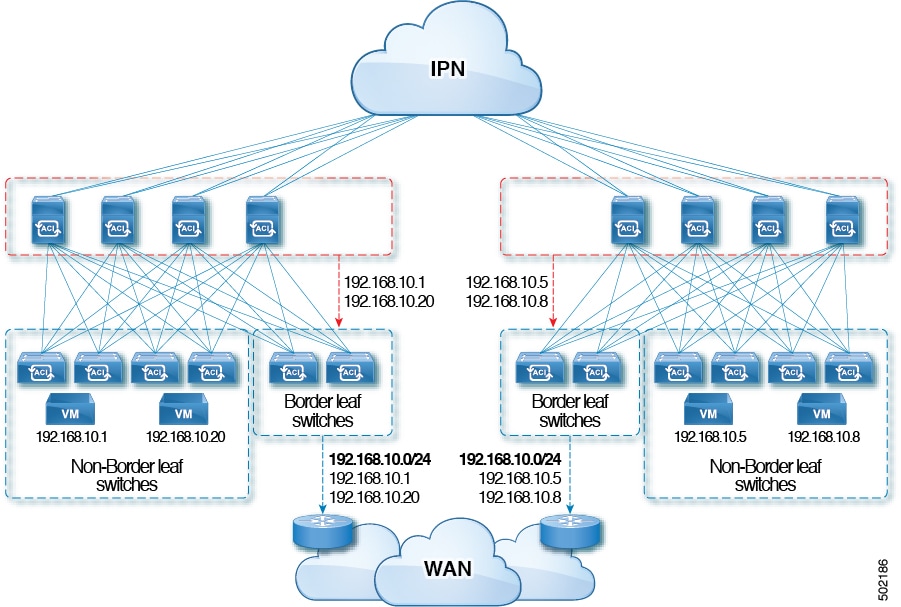
  3. (Optional) Click the box for Advertise Host Routes to enable advertisement to all deployed border leaf switches.

  4. In the VRF field, from the drop-down list, choose the VRF you created (v1 in this example).

  5. Click Next.

  6. Click the + icon on Subnets.

  7. In the Gateway IP field, enter the subnet for the BD.

  8. In the Scope field, choose Advertised Externally.

    Add the L3 Out for Route Profile later, after you create it.

    Note


    If Advertise Host Routes is enabled, the route-map also matches all host routes.

  9. Click OK.

  10. Click Next and click Finish.

Step 3

To create an application EPG, perform the following steps:

  1. Right-click Application Profiles and choose Create Application Profile.

  2. Enter a name for the application.

  3. Click the + icon for EPGs.

  4. Enter a name for the EPG.

  5. From the BD drop-down list, choose the bridge domain you previously created.

  6. Click Update.

  7. Click Submit.

Step 4

To start creating the L3Out, on the Navigation pane, expand Tenant and Networking, then right-click L3Outs and choose Create L3Out.

The Create L3Out wizard appears. The following steps provide the steps for an example L3Out configuration using the Create L3Out wizard.

Step 5

Enter the necessary information in the Identity window of the Create L3Out wizard.

  1. In the Name field, enter a name for the L3Out.

  2. From the VRF drop-down list, choose the VRF.

  3. From the L3 Domain drop-down list, choose the external routed domain that you previously created.

  4. In the area with the routing protocol check boxes, check the desired protocols (BGP, OSPF, or EIGRP).

    For the example in this chapter, choose BGP and OSPF.

    Depending on the protocols you choose, enter the properties that must be set.

  5. Enter the OSPF details, if you enabled OSPF.

    For the example in this chapter, use the OSPF area 0 and type Regular area.

  6. Click Next to move to the Nodes and Interfaces window.

Step 6

Enter the necessary information in the Nodes and Interfaces window of the Create L3Out wizard.

  1. Determine if you want to use the default naming convention.

    In the Use Defaults field, check if you want to use the default node profile name and interface profile names:

    • The default node profile name is L3Out-name_nodeProfile, where L3Out-name is the name that you entered in the Name field in the Identity page.

    • The default interface profile name is L3Out-name_interfaceProfile, where L3Out-name is the name that you entered in the Name field in the Identity page.

  2. In the Interface Types area, make the necessary selections in the Layer 3 and Layer 2 fields.

    The options are:

    • Layer 3:

      • Routed: Select this option to configure a Layer 3 route to the port channels.

        When selecting this option, the Layer 3 route can be to either physical ports or direct port channels, which are selected in the Layer 2 field in this page.

      • Routed Sub: Select this option to configure a Layer 3 sub-interface route to the port channels.

        When selecting this option, the Layer 3 sub-interface route can be to either physical ports or direct port channels, which are selected in the Layer 2 field in this page.

      • SVI: Select this option to configure a Switch Virtual Interface (SVI), which is used to provide connectivity between the ACI leaf switch and a router.

        SVI can have members that are physical ports, direct port channels, or virtual port channels, which are selected in the Layer 2 field in this page.

      • Floating SVI: Select this option to configure floating L3Out.

        Floating L3Out enables you to configure an L3Out that allows a virtual router to move from under one leaf switch to another. The feature saves you from having to configure multiple L3Out interfaces to maintain routing when VMs move from one host to another.

    • Layer 2: (not available if you select Virtual SVI in the Layer 3 area)

      • Port

      • Virtual Port Channel (available if you select SVI in the Layer 3 area)

      • Direct Port Channel

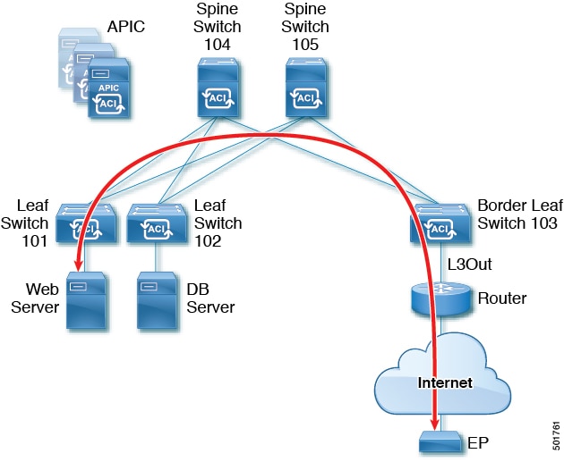
  3. From the Node ID field drop-down menu, choose the node for the L3Out.

    For the topology in these examples, use node 103.

  4. In the Router ID field, enter the router ID (IPv4 or IPv6 address for the router that is connected to the L3Out).

  5. (Optional) You can configure another IP address for a loopback address, if necessary.

    The Loopback Address field is automatically populated with the same entry that you provide in the Router ID field. This is the equivalent of the Use Router ID for Loopback Address option in previous builds. Enter a different IP address for a loopback address, if you don't want to use route ID for the loopback address, or leave this field empty if you do not want to use the router ID for the loopback address.

  6. Enter necessary additional information in the Nodes and Interfaces window.

    The fields shown in this window varies, depending on the options that you select in the Layer 3 and Layer 2 areas.

  7. When you have entered the remaining additional information in the Nodes and Interfaces window, click Next.

    The Protocols window appears.

Step 7

Enter the necessary information in the Protocols window of the Create L3Out wizard.

Because you chose BGP and OSPF as the protocols for this example, the following steps provide information for those fields.

  1. In the BGP Loopback Policies and BGP Interface Policies areas, enter the following information:

    • Peer Address: Enter the peer IP address

    • EBGP Multihop TTL: Enter the connection time to live (TTL). The range is from 1 to 255 hops; if zero, no TTL is specified. The default is zero.

    • Remote ASN: Enter a number that uniquely identifies the neighbor autonomous system. The Autonomous System Number can be in 4-byte as plain format from 1 to 4294967295.

      Note


      ACI does not support asdot or asdot+ format AS numbers.

  2. In the OSPF area, choose the default OSPF policy, a previously created OSPF policy, or Create OSPF Interface Policy.

  3. Click Next.

    The External EPG window appears.

Step 8

Enter the necessary information in the External EPG window of the Create L3Out wizard.

  1. In the Name field, enter a name for the external network.

  2. In the Provided Contract field, enter the name of a provided contract.

  3. In the Consumed Contract field, enter the name of a consumed contract.

  4. In the Default EPG for all external networks field, uncheck if you don’t want to advertise all the transit routes out of this L3Out connection.

    The Subnets area appears if you uncheck this box. Specify the desired subnets and controls as described in the following steps.

  5. Click the + icon to expand Subnet, then perform the following actions in the Create Subnet dialog box.

  6. In the IP address field, enter the IP address and network mask for the external network.

  7. In the Name field, enter the name of the subnet.

  8. In the Scope field, check the appropriate check boxes to control the import and export of prefixes for the L3Out.

    Note


    For more information about the scope options, see the online help for this Create Subnet panel.

  9. (Optional) Click the check box for Export Route Control Subnet.

    The BGP Route Summarization Policy field now becomes available.

  10. In the BGP Route Summarization Policy field, from the drop-down list, choose an existing route summarization policy or create a new one as desired.

    The type of route summarization policy depends on the routing protocols that are enabled for the L3Out.

  11. Click OK when you have completed the necessary configurations in the Create Subnet window.

  12. (Optional) Repeat to add more subnets.

  13. Click Finish to complete the necessary configurations in the Create L3Out wizard.

Step 9

Navigate to the L3Out that you just created, then right-click on the L3Out and select Create Route map for import and export route control.

Step 10

In the Create Route map for import and export route control window, perform the following actions:

  1. In the Name field, enter the route map name.

  2. Choose the Type.

    For this example, leave the default, Match Prefix AND Routing Policy.

  3. Click the + icon to expand Contexts and create a route context for the route map.

  4. Enter the order and name of the profile context.

  5. Choose Deny or Permit for the action to be performed in this context.

  6. (Optional) In the Set Rule field, choose Create Set Rules for a Route Map.

    Enter the name for the set rules, click the objects to be used in the rules, and click Finish.

  7. In the Match Rule field, choose Create Match Rule for a Route Map.

  8. Enter the name for the match rule and enter the Match Regex Community Terms, Match Community Terms, or Match Prefix to match in the rule.

  9. When you have finished filling in the fields in the Create Match Rule window, click Submit.

  10. In the Create Route Control Context dialog box, click OK.

  11. In the Create Route map for import and export route control dialog box, click Submit.

Step 11

In the Navigation pane, expand L3Outs > L3Out_name > External EPGs > externalEPG_name , and perform the following actions:

  1. Click the + icon to expand Route Control Profile.

  2. In the Name field, choose the route control profile that you previously created from the drop-down list.

  3. In the Direction field, choose Route Export Policy.

  4. Click Update.

Step 12

In the Navigation pane, under Tenant_name > Networking expand Bridge Domains.

Note


If the L3Out is static, you are not required to choose any bridge domain settings.

Step 13

Choose the bridge domain that you created.

  1. In the Work pane, click the Policy tab and L3 Configurations.

  2. Click the + icon to expand the Associated L3 Outs field, choose the previously configured L3Out, and click Update.

  3. In the L3Out for Route Profile field, choose the L3Out again.

  4. Click Submit and Submit Changes.

Step 14

Navigate to the L3Out that you just created, then right-click on the L3Out and select Create Route map for import and export route control.

Step 15

In the Create Route map for import and export route control window, perform the following actions.

Note


To set attributes for BGP, OSPF, or EIGRP for received routes, create a default-import route control profile, with the appropriate set actions and no match actions.

  1. In the Name field, choose default-import.

  2. In the Type field, you must select Match Routing Policy Only

  3. In the Create Route map for import and export route control dialog box, click Submit.

Step 16

To enable communications between the EPGs consuming the L3Out, create at least one filter and contract, using the following steps:

  1. In the Navigation pane, under the tenant consuming the L3Out, expand Contracts.

  2. Right-click Filters and choose Create Filter.

  3. In the Name field, enter a filter name.

    A filter is essentially an Access Control List (ACL).

  4. Click the + icon to expand Entries, and add a filter entry.

  5. Add the Entry details.

    For example, for a simple web filter, set criteria such as the following:

    • EtherTypeIP

    • IP Protocoltcp

    • Destination Port Range FromUnspecified

    • Destination Port Range To to https

  6. Click Update.

  7. In the Create Filter dialog box, click Submit.

Step 17

To add a contract, use the following steps:

  1. Under Contracts, right-click Standard and choose Create Contract.

  2. Enter the name of the contract.

  3. Click the + icon to expand Subjects to add a subject to the contract.

  4. Enter a name for the subject.

  5. Click the + icon to expand Filters and choose the filter that you previously created from the drop-down list.

  6. Click Update.

  7. In the Create Contract Subject dialog box, click OK.

  8. In the Create Contract dialog box, click Submit.

Step 18

Associate the EPGs for the L3Out with the contract, with the following steps:

In this example, the L3 external EPG (extnw1) is the provider and the application EPG (epg1) is the consumer.

  1. To associate the contract to the L3 external EPG, as the provider, under the tenant, click Networking, expand L3Outs, and expand the L3Out.

  2. Expand External EPGs, click the L3 external EPG, and click the Contracts tab.

  3. Click the the + icon to expand Provided Contracts.

  4. In the Name field, choose the contract that you previously created from the list.

  5. Click Update.

  6. To associate the contract to an application EPG, as a consumer, under the tenant, navigate to Application Profiles > app-prof-name > Application EPGs > and expand the app-epg-name.

  7. Right-click Contracts, and choose Add Consumed Contract.

  8. On the Contract field, choose the contract that you previously created.

  9. Click Submit.