Remote Leaf Switches

This chapter contains the following sections:

About Remote Leaf Switches in the ACI Fabric

With an ACI fabric deployed, you can extend ACI services and APIC management to remote data centers with Cisco ACI leaf switches that have no local spine switch or APIC attached.

The remote leaf switches are added to an existing pod in the fabric. All policies deployed in the main data center are deployed in the remote switches, which behave like local leaf switches belonging to the pod. In this topology, all unicast traffic is through VXLAN over Layer 3. Layer 2 broadcast, unknown unicast, and multicast (BUM) messages are sent using Head End Replication (HER) tunnels without the use of Layer 3 multicast (bidirectional PIM) over the WAN. Any traffic that requires use of the spine switch proxy is forwarded to the main data center.

The APIC system discovers the remote leaf switches when they come up. From that time, they can be managed through APIC, as part of the fabric.


Note


  • All inter-VRF traffic (pre-release 4.0(1)) goes to the spine switch before being forwarded.

  • For releases prior to Release 4.1(2), before decommissioning a remote leaf switch, you must first delete the vPC.


Characteristics of Remote Leaf Switch Behavior in Release 4.0(1)

Starting in Release 4.0(1), Remote Leaf behavior takes on the following characteristics:

  • Reduction of WAN bandwidth use by decoupling services from spine-proxy:

    • PBR: For local PBR devices or PBR devices behind a vPC, local switching is used without going to the spine proxy. For PBR devices on orphan ports on a peer remote leaf, a RL-vPC tunnel is used. This is true when the spine link to the main DC is functional or not functional.

    • ERSPAN: For peer destination EPGs, a RL-vPC tunnel is used. EPGs on local orphan or vPC ports use local switching to the destination EPG. This is true when the spine link to the main DC is functional or not functional.

    • Shared Services: Packets do not use spine-proxy path reducing WAN bandwidth consumption.

    • Inter-VRF traffic is forwarded through an upstream router and not placed on the spine.

    • This enhancement is only applicable for a remote leaf vPC pair. For communication across remote leaf pairs, a spine proxy is still used.

  • Resolution of unknown L3 endpoints (through ToR glean process) in a remote leaf location when spine-proxy is not reachable.

Characteristics of Remote Leaf Switch Behavior in Release 4.1(2)

Before Release 4.1(2), all local switching (within the remote leaf vPC peer) traffic on the remote leaf location is switched directly between endpoints, whether physical or virtual, as shown in the following figure.

Figure 1. Local Switching Traffic: Prior to Release 4.1(2)

In addition, before Release 4.1(2), traffic between the remote leaf switch vPC pairs, either within a remote location or between remote locations, is forwarded to the spine switches in the ACI main data center pod, as shown in the following figure.
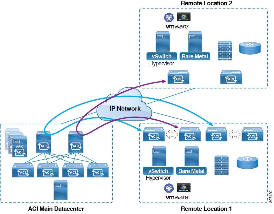
Figure 2. Remote Switching Traffic: Prior to Release 4.1(2)

Starting in Release 4.1(2), support is now available for direct traffic forwarding between remote leaf switches in different remote locations. This functionality offers a level of redundancy and availability in the connections between remote locations, as shown in the following figure.
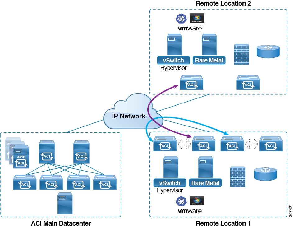
Figure 3. Remote Leaf Switch Behavior: Release 4.1(2)

In addition, remote leaf switch behavior also takes on the following characteristics starting in release 4.1(2):

  • Starting with Release 4.1(2), with direct traffic forwarding, when a spine switch fails within a single-pod configuration, the following occurs:

    • Local switching will continue to function for existing and new end point traffic between the remote leaf switch vPC peers, as shown in the "Local Switching Traffic: Prior to Release 4.1(2)" figure above.

    • For traffic between remote leaf switches across remote locations:

      • New end point traffic will fail because the remote leaf switch-to-spine switch tunnel would be down. From the remote leaf switch, new end point details will not get synced to the spine switch, so the other remote leaf switch pairs in the same or different locations cannot download the new end point information from COOP.

      • For uni-directional traffic, existing remote end points will age out after 300 secs, so traffic will fail after that point. Bi-directional traffic within a remote leaf site (between remote leaf VPC pairs) in a pod will get refreshed and will continue to function. Note that Bi-directional traffic to remote locations (remote leaf switches) will be affected as the remote end points will be expired by COOP after a timeout of 900 seconds.

      • Bi-directional traffic within a remote leaf site (between remote leaf VPC pairs) in a pod will get refreshed and will continue to function. Note that Bi-directional traffic to remote locations (remote leaf switches) will be affected as the remote end points will be expired by COOP after a timeout of 900 seconds.

      • For shared services (inter-VRF), bi-directional traffic between end points belonging to remote leaf switches attached to two different remote locations in the same pod will fail after the remote leaf switch COOP end point age-out time (900 sec). This is because the remote leaf switch-to-spine COOP session would be down in this situation. However, shared services traffic between end points belonging to remote leaf switches attached to two different pods will fail after 30 seconds, which is the COOP fast-aging time.

      • L3Out-to-L3Out communication would not be able to continue because the BGP session to the spine switches would be down.

  • When there is remote leaf direct uni-directional traffic, where the traffic is from remote leaf switch to remote leaf switch or from remote leaf switch to local leaf switch, there will be a milli-second traffic loss every time the remote end point (XR EP) timeout of 300 seconds occurs.

You can configure Remote Leaf in the APIC GUI, either with and without a wizard, or use the REST API or the NX-OS style CLI.

Remote Leaf Switch Hardware Requirements

The following switches are supported for the Remote Leaf Switch feature.

Fabric Spine Switches

For the spine switch at the ACI Main Datacenter that is connected to the WAN router, the following spine switches are supported:

  • Fixed spine switches Cisco Nexus 9000 series:

    • N9K-C9316D-GX

    • N9K-C9332C

    • N9K-C9364C

    • N9K-C9364C-GX

  • For modular spine switches, only Cisco Nexus 9000 series switches with names that end in EX, and later (for example, N9K-X9732C- EX ) are supported.

  • Older generation spine switches, such as the fixed spine switch N9K-C9336PQ or modular spine switches with the N9K-X9736PQ linecard are supported in the Main Datacenter, but only next generation spine switches are supported to connect to the WAN.

Remote Leaf Switches

  • For the remote leaf switches, only Cisco Nexus 9000 series switches with names that end in EX, and later (for example, N9K-C93180LC-EX) are supported.

  • The remote leaf switches must be running a switch image of 13.1.x or later (aci-n9000-dk9.13.1.x.x.bin) before they can be discovered. This may require manual upgrades on the leaf switches.

Remote Leaf Switch Restrictions and Limitations

The following guidelines and restrictions apply to remote leaf switches:

  • A remote leaf vPC pair has a split brain condition when the DP-TEP address of one of the switches is not reachable from the peer. In this case, both remote leaf switches are up and active in the fabric and the COOP session is also up on both of the peers. One of the remote leaf switches does not have a route to the DP-TEP address of its peer, and due to this, the vPC has a split brain condition. Both of the node roles is changed to "primary" and all the front panel links are up in both of the peers while the zero message queue (ZMQ) session is down.

  • The remote leaf solution requires the /32 tunnel end point (TEP) IP addresses of the remote leaf switches and main data center leaf/spine switches to be advertised across the main data center and remote leaf switches without summarization.

  • If you move a remote leaf switch to a different site within the same pod and the new site has the same node ID as the original site, you must delete and recreate the virtual port channel (vPC).

  • With the Cisco N9K-C9348GC-FXP switch, you can perform the initial remote leaf switch discovery only on ports 1/53 or 1/54. Afterward, you can use the other ports for fabric uplinks to the ISN/IPN for the remote leaf switch.

The following sections provide information on what is supported and not supported with remote leaf switches:

Supported Features

Beginning with Cisco APIC release 4.1(2), the following features are supported:

  • Remote leaf switches with ACI Multi-Site

  • Traffic forwarding directly across two remote leaf vPC pairs in the same remote data center or across data centers, when those remote leaf pairs are associated to the same pod or to pods that are part of the same multipod fabric

  • Transit L3Out across remote locations, which is when the main Cisco ACI data center pod is a transit between two remote locations (the L3Out in RL location-1 and L3Out in RL location-2 are advertising prefixes for each other)

Beginning with Cisco APIC release 4.0(1), the following features are supported:

  • Q-in-Q Encapsulation Mapping for EPGs

  • PBR Tracking on remote leaf switches (with system-level global GIPo enabled)

  • PBR Resilient Hashing

  • Netflow

  • MacSec Encryption

  • Troubleshooting Wizard

  • Atomic counters

Unsupported Features

Full fabric and tenant policies are supported on remote leaf switches in this release with the exception of the following features, which are unsupported:

  • GOLF

  • vPod

  • Floating L3Out

  • Fast-convergence mode

  • Stretching of L3Out SVI between local leaf switches (ACI main data center switches) and remote leaf switches or stretching across two different vPC pairs of remote leaf switches

  • Copy service is not supported when deployed on local leaf switches and when the source or destination is on the remote leaf switch. In this situation, the routable TEP IP address is not allocated for the local leaf switch. For more information, see the section "Copy Services Limitations" in the "Configuring Copy Services" chapter in the Cisco APIC Layer 4 to Layer 7 Services Deployment Guide, available in the APIC documentation page.

  • Layer 2 Outside Connections (except Static EPGs)

  • 802.1Q Tunnels

  • Copy services with vzAny contract

  • FCoE connections on remote leaf switches

  • Flood in encapsulation for bridge domains or EPGs

  • Fast Link Failover policies

  • Managed Service Graph-attached devices at remote locations

  • Traffic Storm Control

  • Cloud Sec Encryption

  • First Hop Security

  • Layer 3 Multicast routing on remote leaf switches

  • Maintenance mode

  • TEP to TEP atomic counters

The following scenarios are not supported when integrating remote leaf switches in a Multi-Site architecture in conjunction with the intersite L3Out functionality:

  • Transit routing between L3Outs deployed on remote leaf switch pairs associated to separate sites

  • Endpoints connected to a remote leaf switch pair associated to a site communicating with the L3Out deployed on the remote leaf switch pair associated to a remote site

  • Endpoints connected to the local site communicating with the L3Out deployed on the remote leaf switch pair associated to a remote site

  • Endpoints connected to a remote leaf switch pair associated to a site communicating with the L3Out deployed on a remote site


Note


The limitations above do not apply if the different data center sites are deployed as pods as part of the same Multi-Pod fabric.


The following deployments and configurations are not supported with the remote leaf switch feature:

  • It is not supported to stretch a bridge domain between remote leaf nodes associated to a given site (APIC domain) and leaf nodes part of a separate site of a Multi-Site deployment (in both scenarios where those leaf nodes are local or remote) and a fault is generated on APIC to highlight this restriction. This applies independently from the fact that BUM flooding is enabled or disabled when configuring the stretched bridge domain on the Multi-Site Orchestrator (MSO). However, a bridge domain can always be stretched (with BUM flooding enabled or disabled) between remote leaf nodes and local leaf nodes belonging to the same site (APIC domain).

  • Spanning Tree Protocol across remote leaf location and main data center

  • APICs directly connected to remote leaf switches

  • Orphan port channel or physical ports on remote leaf switches, with a vPC domain (this restriction applies for releases 3.1 and earlier)

  • With and without service node integration, local traffic forwarding within a remote location is only supported if the consumer, provider, and services nodes are all connected to remote leaf switches are in vPC mode

  • /32 loopbacks advertised from the spine switch to the IPN must not be suppressed/aggregated toward the remote leaf switch. The /32 loopbacks must be advertised to the remote leaf switch.

  • Service devices part of the same service graph must not be distributed across remote leaf location and main data center. The consumers and the provider endpoints can be spread across remote location and main data center

WAN Router and Remote Leaf Switch Configuration Guidelines

Before a remote leaf is discovered and incorporated in APIC management, you must configure the WAN router and the remote leaf switches.

Configure the WAN routers that connect to the fabric spine switch external interfaces and the remote leaf switch ports, with the following requirements:

WAN Routers

  • Enable OSPF on the interfaces, with the same details, such as area ID, type, and cost.

  • Configure DHCP Relay on the interface leading to each APIC's IP address in the main fabric.

  • The interfaces on the WAN routers which connect to the VLAN-5 interfaces on the spine switches must be on different VRFs than the interfaces connecting to a regular multipod network.

Remote Leaf Switches

  • Connect the remote leaf switches to an upstream router by a direct connection from one of the fabric ports. The following connections to the upstream router are supported:

    • 40 Gbps & higher connections

    • With a QSFP-to-SFP Adapter, supported 1G/10G SFPs

    Bandwidth in the WAN must be a minimum of 100 Mbps and maximum supported latency is 300 msecs.

  • It is recommended, but not required to connect the pair of remote leaf switches with a vPC. The switches on both ends of the vPC must be remote leaf switches at the same remote datacenter.

  • Configure the northbound interfaces as Layer 3 sub-interfaces on VLAN-4, with unique IP addresses.

    If you connect more than one interface from the remote leaf switch to the router, configure each interface with a unique IP address.

  • Enable OSPF on the interfaces, but do not set the OSPF area type as stub area.

  • The IP addresses in the remote leaf switch TEP Pool subnet must not overlap with the pod TEP subnet pool. The subnet used must be /24 or lower.

  • Multipod is supported, but not required, with the Remote Leaf feature.

  • When connecting a pod in a single-pod fabric with remote leaf switches, configure an L3Out from a spine switch to the WAN router and an L3Out from a remote leaf switch to the WAN router, both using VLAN-4 on the switch interfaces.

  • When connecting a pod in a multipod fabric with remote leaf switches, configure an L3Out from a spine switch to the WAN router and an L3Out from a remote leaf switch to the WAN router, both using VLAN-4 on the switch interfaces. Also configure a multipod-internal L3Out using VLAN-5 to support traffic that crosses pods destined to a remote leaf switch. The regular multipod and multipod-internal connections can be configured on the same physical interfaces, as long as they use VLAN-4 and VLAN-5.

  • When configuring the Multipod-internal L3Out, use the same router ID as for the regular multipod L3Out, but deselect the Use Router ID as Loopback Address option for the router-id and configure a different loopback IP address. This enables ECMP to function.

Configure Remote Leaf Switches Using the REST API

To enable Cisco APIC to discover and connect the IPN router and remote leaf switches, perform the steps in this topic.

This example assumes that the remote leaf switches are connected to a pod in a multipod topology. It includes two L3Outs configured in the infra tenant, with VRF overlay-1:

  • One is configured on VLAN-4, that is required for both the remote leaf switches and the spine switch that is connected to the WAN router.

  • One is the multipod-internal L3Out configured on VLAN-5, that is required for the multipod and Remote Leaf features, when they are deployed together.

Procedure


Step 1

To define the TEP pool for two remote leaf switches to be connected to a pod, send a post with XML such as the following example:

Example:

<fabricSetupPol>
      <fabricSetupP tepPool="10.0.0.0/16" podId="1" >
           <fabricExtSetupP tepPool="30.0.128.0/20" extPoolId="1"/>
     </fabricSetupP>
     <fabricSetupP tepPool="10.1.0.0/16" podId="2" >
          <fabricExtSetupP tepPool="30.1.128.0/20" extPoolId="1"/>
     </fabricSetupP>
</fabricSetupPol>

Step 2

To define the node identity policy, send a post with XML, such as the following example:

Example:

<fabricNodeIdentPol>
     <fabricNodeIdentP serial="SAL17267Z7W" name="leaf1" nodeId="101" podId="1" 
extPoolId="1" nodeType="remote-leaf-wan"/>
     <fabricNodeIdentP serial="SAL17267Z7X" name="leaf2" nodeId="102" podId="1" 
extPoolId="1" nodeType="remote-leaf-wan"/>
     <fabricNodeIdentP serial="SAL17267Z7Y" name="leaf3" nodeId="201" podId="1" 
extPoolId="1" nodeType="remote-leaf-wan"/>
     <fabricNodeIdentP serial="SAL17267Z7Z" name="leaf4" nodeId="201" podId="1" 
extPoolId="1" nodeType="remote-leaf-wan"/>
</fabricNodeIdentPol>

Step 3

To configure the Fabric External Connection Profile, send a post with XML such as the following example:

Example:

<?xml version="1.0" encoding="UTF-8"?>
<imdata totalCount="1">
     <fvFabricExtConnP dn="uni/tn-infra/fabricExtConnP-1" id="1" name="Fabric_Ext_Conn_Pol1" rt="extended:as2-nn4:5:16" siteId="0">
           <l3extFabricExtRoutingP name="test">
                <l3extSubnet ip="150.1.0.0/16" scope="import-security"/>
           </l3extFabricExtRoutingP>
          <l3extFabricExtRoutingP name="ext_routing_prof_1">
               <l3extSubnet ip="204.1.0.0/16" scope="import-security"/>
               <l3extSubnet ip="209.2.0.0/16" scope="import-security"/>
               <l3extSubnet ip="202.1.0.0/16" scope="import-security"/>
               <l3extSubnet ip="207.1.0.0/16" scope="import-security"/>
               <l3extSubnet ip="200.0.0.0/8" scope="import-security"/>
               <l3extSubnet ip="201.2.0.0/16" scope="import-security"/>
               <l3extSubnet ip="210.2.0.0/16" scope="import-security"/>
               <l3extSubnet ip="209.1.0.0/16" scope="import-security"/>
               <l3extSubnet ip="203.2.0.0/16" scope="import-security"/>
               <l3extSubnet ip="208.1.0.0/16" scope="import-security"/>
               <l3extSubnet ip="207.2.0.0/16" scope="import-security"/>
               <l3extSubnet ip="100.0.0.0/8" scope="import-security"/>
               <l3extSubnet ip="201.1.0.0/16" scope="import-security"/>
               <l3extSubnet ip="210.1.0.0/16" scope="import-security"/>
               <l3extSubnet ip="203.1.0.0/16" scope="import-security"/>
               <l3extSubnet ip="208.2.0.0/16" scope="import-security"/>
          </l3extFabricExtRoutingP>
          <fvPodConnP id="1">
                <fvIp addr="100.11.1.1/32"/>
         </fvPodConnP>
         <fvPodConnP id="2">
               <fvIp addr="200.11.1.1/32"/>
         </fvPodConnP>
         <fvPeeringP type="automatic_with_full_mesh"/>
     </fvFabricExtConnP>
</imdata>

Step 4

To configure an L3Out on VLAN-4, that is required for both the remote leaf switches and the spine switch connected to the WAN router, enter XML such as the following example.

Example:

<?xml version="1.0" encoding="UTF-8"?>
<polUni>
<fvTenant name="infra">
  <l3extOut name="rleaf-wan-test">
    <ospfExtP areaId="0.0.0.5"/>
    <bgpExtP/>
    <l3extRsEctx tnFvCtxName="overlay-1"/>
    <l3extRsL3DomAtt tDn="uni/l3dom-l3extDom1"/>
    <l3extProvLbl descr="" name="prov_mp1" ownerKey="" ownerTag="" tag="yellow-green"/>
    <l3extLNodeP name="rleaf-101">
      <l3extRsNodeL3OutAtt rtrId="202.202.202.202" tDn="topology/pod-1/node-101">
      </l3extRsNodeL3OutAtt>
      <l3extLIfP name="portIf">
        <l3extRsPathL3OutAtt ifInstT="sub-interface" tDn="topology/pod-1/paths-101/pathep-[eth1/49]" addr="202.1.1.2/30" mac="AA:11:22:33:44:66" encap='vlan-4'/>
        <ospfIfP>
          <ospfRsIfPol tnOspfIfPolName='ospfIfPol'/>
        </ospfIfP>
      </l3extLIfP>
    </l3extLNodeP>
    <l3extLNodeP name="rlSpine-201">
      <l3extRsNodeL3OutAtt rtrId="201.201.201.201" rtrIdLoopBack="no" tDn="topology/pod-1/node-201">
        <!--
        <l3extLoopBackIfP addr="201::201/128" descr="" name=""/>
        <l3extLoopBackIfP addr="201.201.201.201/32" descr="" name=""/>
        -->
        <l3extLoopBackIfP addr="::" />
      </l3extRsNodeL3OutAtt>
      <l3extLIfP name="portIf">
        <l3extRsPathL3OutAtt ifInstT="sub-interface" tDn="topology/pod-1/paths-201/pathep-[eth8/36]" addr="201.1.1.1/30" mac="00:11:22:33:77:55" encap='vlan-4'/>
        <ospfIfP>
          <ospfRsIfPol tnOspfIfPolName='ospfIfPol'/>
        </ospfIfP>
      </l3extLIfP>
    </l3extLNodeP>
    <l3extInstP descr="" matchT="AtleastOne" name="instp1" prio="unspecified" targetDscp="unspecified">
      <fvRsCustQosPol tnQosCustomPolName=""/>
    </l3extInstP>
  </l3extOut>
  <ospfIfPol name="ospfIfPol" nwT="bcast"/>
</fvTenant>
</polUni>

Step 5

For releases prior to Release 4.1(2), to configure the multipod L3Out on VLAN-5, that is required for both multipod and the remote leaf topology, send a post such as the following example.

Note


Do not enter this information if you are deploying new remote leaf switches running Release 4.1(2) or later and you are enabling direct traffic forwarding on those remote leaf switches. Configuring an OSPF instance using VLAN-5 for multipod is not needed in this case.

See About Direct Traffic Forwarding for more information.

Example:

<?xml version="1.0" encoding="UTF-8"?>                    
<polUni>                                                                                               
  <fvTenant  name="infra" >
    <l3extOut name="ipn-multipodInternal">
      <ospfExtP areaCtrl="inherit-ipsec,redistribute,summary" areaId="0.0.0.5" multipodInternal="yes" />
      <l3extRsEctx tnFvCtxName="overlay-1" />
      <l3extLNodeP name="bLeaf">
        <l3extRsNodeL3OutAtt rtrId="202.202.202.202" rtrIdLoopBack="no" tDn="topology/pod-2/node-202">
            <l3extLoopBackIfP addr="202.202.202.212"/>
       </l3extRsNodeL3OutAtt>
        <l3extRsNodeL3OutAtt rtrId="102.102.102.102" rtrIdLoopBack="no" tDn="topology/pod-1/node-102">
            <l3extLoopBackIfP addr="102.102.102.112"/>
       </l3extRsNodeL3OutAtt>
        <l3extLIfP name="portIf">
          <ospfIfP authKeyId="1" authType="none">
            <ospfRsIfPol tnOspfIfPolName="ospfIfPol" />
          </ospfIfP>
          <l3extRsPathL3OutAtt addr="10.0.254.233/30" encap="vlan-5" ifInstT="sub-interface" tDn="topology/pod-2/paths-202/pathep-[eth5/2]"/>
          <l3extRsPathL3OutAtt addr="10.0.255.229/30" encap="vlan-5" ifInstT="sub-interface" tDn="topology/pod-1/paths-102/pathep-[eth5/2]"/>
        </l3extLIfP>
      </l3extLNodeP>
      <l3extInstP matchT="AtleastOne" name="ipnInstP" />
    </l3extOut>
  </fvTenant>
</polUni>

Configure Remote Leaf Switches Using the NX-OS Style CLI

This example configures a spine switch and a remote leaf switch to enable the leaf switch to communicate with the main fabric pod.

Before you begin

  • The IPN router and remote leaf switches are active and configured; see WAN Router and Remote Leaf Switch Configuration Guidelines.

  • The remote leaf switches are running a switch image of 13.1.x or later (aci-n9000-dk9.13.1.x.x.bin).

  • The pod in which you plan to add the remote leaf switches is created and configured.

Procedure


Step 1

Define the TEP pool for a remote location 5, in pod 2.

The network mask must be /24 or lower.

Use the following new command: system remote-leaf-site site-id pod pod-id tep-pool ip-address-and-netmask

Example:

apic1(config)# system remote-leaf-site 5 pod 2 tep-pool 192.0.0.0/16

Step 2

Add a remote leaf switch to pod 2, remote-leaf-site 5.

Use the following command: system switch-id serial-number node-id leaf-switch-name pod pod-id remote-leaf-site remote-leaf-site-id node-type remote-leaf-wan

Example:

apic1(config)# system switch-id FDO210805SKD 109 ifav4-leaf9 pod 2 
remote-leaf-site 5 node-type remote-leaf-wan

Step 3

Configure a VLAN domain with a VLAN that includes VLAN 4.

Example:

apic1(config)# vlan-domain ospfDom
apic1(config-vlan)# vlan 4-5   
apic1(config-vlan)# exit  

Step 4

Configure two L3Outs for the infra tenant, one for the remote leaf connections and one for the multipod IPN.

Example:


apic1(config)# tenant infra       
apic1(config-tenant)# l3out rl-wan
apic1(config-tenant-l3out)# vrf member overlay-1
apic1(config-tenant-l3out)# exit                
apic1(config-tenant)# l3out ipn-multipodInternal            
apic1(config-tenant-l3out)# vrf member overlay-1
apic1(config-tenant-l3out)# exit                
apic1(config-tenant)# exit                      
apic1(config)#       

Step 5

Configure the spine switch interfaces and sub-interfaces to be used by the L3Outs.

Example:


apic1(config)# spine 201                        
apic1(config-spine)# vrf context tenant infra vrf overlay-1 l3out rl-wan-test
apic1(config-spine-vrf)# exit                                            
apic1(config-spine)# vrf context tenant infra vrf overlay-1 l3out ipn-multipodInternal
apic1(config-spine-vrf)# exit                                             
apic1(config-spine)#                                                      
apic1(config-spine)# interface ethernet 8/36                              
apic1(config-spine-if)# vlan-domain member ospfDom                        
apic1(config-spine-if)# exit                                              
apic1(config-spine)# router ospf default                                  
apic1(config-spine-ospf)# vrf member tenant infra vrf overlay-1           
apic1(config-spine-ospf-vrf)# area 5 l3out rl-wan-test
apic1(config-spine-ospf-vrf)# exit
apic1(config-spine-ospf)# exit
apic1(config-spine)#
apic1(config-spine)# interface ethernet 8/36.4
apic1(config-spine-if)# vrf member tenant infra vrf overlay-1 l3out rl-wan-test
apic1(config-spine-if)# ip router ospf default area 5
apic1(config-spine-if)# exit
apic1(config-spine)# router ospf multipod-internal
apic1(config-spine-ospf)# vrf member tenant infra vrf overlay-1
apic1(config-spine-ospf-vrf)# area 5 l3out ipn-multipodInternal
apic1(config-spine-ospf-vrf)# exit
apic1(config-spine-ospf)# exit
apic1(config-spine)#
apic1(config-spine)# interface ethernet 8/36.5
apic1(config-spine-if)# vrf member tenant infra vrf overlay-1 l3out ipn-multipodInternal
apic1(config-spine-if)# ip router ospf multipod-internal area 5
apic1(config-spine-if)# exit
apic1(config-spine)# exit
apic1(config)#

Step 6

Configure the remote leaf switch interface and sub-interface used for communicating with the main fabric pod.

Example:

(config)# leaf 101                        
apic1(config-leaf)# vrf context tenant infra vrf overlay-1 l3out rl-wan-test
apic1(config-leaf-vrf)# exit     
apic1(config-leaf)#                                                      
apic1(config-leaf)# interface ethernet 1/49                              
apic1(config-leaf-if)# vlan-domain member ospfDom                        
apic1(config-leaf-if)# exit                                              
apic1(config-leaf)# router ospf default                                  
apic1(config-leaf-ospf)# vrf member tenant infra vrf overlay-1           
apic1(config-leaf-ospf-vrf)# area 5 l3out rl-wan-test
apic1(config-leaf-ospf-vrf)# exit
apic1(config-leaf-ospf)# exit
apic1(config-leaf)#
apic1(config-leaf)# interface ethernet 1/49.4
apic1(config-leaf-if)# vrf member tenant infra vrf overlay-1 l3out rl-wan-test
apic1(config-leaf-if)# ip router ospf default area 5
apic1(config-leaf-if)# exit

Example

The following example provides a downloadable configuration:

apic1# configure
apic1(config)# system remote-leaf-site 5 pod 2 tep-pool 192.0.0.0/16 
apic1(config)# system switch-id FDO210805SKD 109 ifav4-leaf9 pod 2 
remote-leaf-site 5 node-type remote-leaf-wan                   
apic1(config)# vlan-domain ospfDom
apic1(config-vlan)# vlan 4-5   
apic1(config-vlan)# exit          
apic1(config)# tenant infra       
apic1(config-tenant)# l3out rl-wan-test
apic1(config-tenant-l3out)# vrf member overlay-1
apic1(config-tenant-l3out)# exit                
apic1(config-tenant)# l3out ipn-multipodInternal            
apic1(config-tenant-l3out)# vrf member overlay-1
apic1(config-tenant-l3out)# exit                
apic1(config-tenant)# exit                      
apic1(config)#                                  
apic1(config)# spine 201                        
apic1(config-spine)# vrf context tenant infra vrf overlay-1 l3out rl-wan-test
apic1(config-spine-vrf)# exit                                            
apic1(config-spine)# vrf context tenant infra vrf overlay-1 l3out ipn-multipodInternal
apic1(config-spine-vrf)# exit                                             
apic1(config-spine)#                                                      
apic1(config-spine)# interface ethernet 8/36                              
apic1(config-spine-if)# vlan-domain member ospfDom                        
apic1(config-spine-if)# exit                                              
apic1(config-spine)# router ospf default                                  
apic1(config-spine-ospf)# vrf member tenant infra vrf overlay-1           
apic1(config-spine-ospf-vrf)# area 5 l3out rl-wan-test
apic1(config-spine-ospf-vrf)# exit
apic1(config-spine-ospf)# exit
apic1(config-spine)#
apic1(config-spine)# interface ethernet 8/36.4
apic1(config-spine-if)# vrf member tenant infra vrf overlay-1 l3out rl-wan-test
apic1(config-spine-if)# ip router ospf default area 5
apic1(config-spine-if)# exit
apic1(config-spine)# router ospf multipod-internal
apic1(config-spine-ospf)# vrf member tenant infra vrf overlay-1
apic1(config-spine-ospf-vrf)# area 5 l3out ipn-multipodInternal
apic1(config-spine-ospf-vrf)# exit
apic1(config-spine-ospf)# exit
apic1(config-spine)#
apic1(config-spine)# interface ethernet 8/36.5
apic1(config-spine-if)# vrf member tenant infra vrf overlay-1 l3out ipn-multipodInternal
apic1(config-spine-if)# ip router ospf multipod-internal area 5
apic1(config-spine-if)# exit
apic1(config-spine)# exit
apic1(config)#
apic1(config)# leaf 101                        
apic1(config-leaf)# vrf context tenant infra vrf overlay-1 l3out rl-wan-test
apic1(config-leaf-vrf)# exit     
apic1(config-leaf)#                                                      
apic1(config-leaf)# interface ethernet 1/49                              
apic1(config-leaf-if)# vlan-domain member ospfDom                        
apic1(config-leaf-if)# exit                                              
apic1(config-leaf)# router ospf default                                  
apic1(config-leaf-ospf)# vrf member tenant infra vrf overlay-1           
apic1(config-leaf-ospf-vrf)# area 5 l3out rl-wan-test
apic1(config-leaf-ospf-vrf)# exit
apic1(config-leaf-ospf)# exit
apic1(config-leaf)#
apic1(config-leaf)# interface ethernet 1/49.4
apic1(config-leaf-if)# vrf member tenant infra vrf overlay-1 l3out rl-wan-test
apic1(config-leaf-if)# ip router ospf default area 5
apic1(config-leaf-if)# exit

Configure the Pod and Fabric Membership for Remote Leaf Switches Using the GUI

You can configure and enable Cisco APIC to discover and connect the IPN router and remote switches, either by using a wizard or by using the APIC GUI, without a wizard.

Configure the Pod and Fabric Membership for Remote Leaf Switches Using a Wizard: Releases Prior to 4.1(2)

You can configure and enable Cisco APIC to discover and connect the IPN router and remote switches, using a wizard as in this topic, or in an alternative method using the APIC GUI. See Configure the Pod and Fabric Membership for Remote Leaf Switches Using the GUI (Without a Wizard).


Note


These procedures describe how to configure the remote leaf switches using the wizard for releases prior to 4.1(2). For instructions on configuring the remote leaf switches using the wizard for Release 4.1(2) and later, see Configure the Pod and Fabric Membership for Remote Leaf Switches Using a Wizard: Releases 4.1(2) and Later.


Before you begin

  • The IPN and WAN routers and remote leaf switches are active and configured; see WAN Router and Remote Leaf Switch Configuration Guidelines.

  • The remote leaf switch pair are connected with a vPC.

  • The remote leaf switches are running a switch image of 13.1.x or later (aci-n9000-dk9.13.1.x.x.bin).

  • The pod in which you plan to add the remote leaf switches is created and configured.

  • The spine switch that will be used to connect the pod with the remote leaf swiches is connected to the IPN router.

Procedure


Step 1

On the menu bar click Fabric > Inventory.

Step 2

In the Navigation pane, expand Quick Start and click Node or Pod Setup.

Step 3

In the Remote Leaf pane of the working pane, click Setup Remote Leaf or right-click Node or Pod Setup and click Setup Remote Leaf.

Step 4

Follow the instructions to configure the following:

  • Pod Fabric—Identify the pod and the TEP Pool subnet for the remote leaf switches.

    Add the comma-separated subnets for the underlay routes leading to the remote leaf switches.

    Repeat this for the other remote leaf switches to be added to the pod.

  • Fabric Membership—Set up fabric membership for the remote leaf switches, including the node ID, Remote Leaf TEP Pool ID, and Remote Leaf Switch name.

  • Remote Leaf—Configure Layer 3 details for the remote leaf switches, including the OSPF details (the same OSPF configuration as in the WAN router), the router IDs and loopback addresses, and routed sub-interfaces for nodes.

  • Connections—Configure the Layer 3 details for the spine switch for the L3Out on the route to the remote leaf switches (only required if you are adding remote leaf switches to a single-pod fabric), including the OSPF details (same as configured in the IPN and WAN routers), the OSPF Profile, router IDs and routed sub-interfaces for the spine switches.

Step 5

On the menu bar click System > System Settings.

Step 6

In the Navigation pane, choose System Global GIPo.

Step 7

For Use Infra GIPo as System GIPo, choose Enabled.


Configure the Pod and Fabric Membership for Remote Leaf Switches Using a Wizard: Releases 4.1(2) and Later

You can configure and enable Cisco APIC to discover and connect the IPN router and remote switches, using a wizard as in this topic, or in an alternative method using the APIC GUI. See Configure the Pod and Fabric Membership for Remote Leaf Switches Using the GUI (Without a Wizard).


Note


These procedures describe how to configure the remote leaf switches using the wizard for Release 4.1(2) and later. For instructions on configuring the remote leaf switches using the wizard for releases prior to 4.1(2), see Configure the Pod and Fabric Membership for Remote Leaf Switches Using a Wizard: Releases Prior to 4.1(2).


Before you begin

  • The IPN and WAN routers and remote leaf switches are active and configured; see WAN Router and Remote Leaf Switch Configuration Guidelines.

  • The remote leaf switch pair are connected with a vPC.

  • The remote leaf switches are running a switch image of 14.1.x or later (aci-n9000-dk9.14.1.x.x.bin).

  • The pod in which you plan to add the remote leaf switches is created and configured.

  • The spine switch that will be used to connect the pod with the remote leaf swiches is connected to the IPN router.

Procedure


Step 1

On the menu bar click Fabric > Inventory.

Step 2

In the Navigation pane, expand Quick Start and click Add Remote Leaf.

Step 3

In the Remote Leaf pane of the working pane, click Add Remote Leaf.

Step 4

Configure the interpod connectivity before adding the remote leaf switch, if necessary.

You will see the Configure Interpod Connectivity screen if you do not have connections configured yet between the physical Pod and the IPN connectivity. This connectivity is a prerequisite before extending ACI to another location. You will configure the IP connectivity, routing protocols, and external TEP addresses in this part of the configuration wizard in this situation.

For information on configuring interpod connectivity, see Preparing the Pod for IPN Connectivity.

Step 5

At the end of the process for configuring interpod connectivity, click Add Remote Leaf in the Summary page.

The Add Remote Leaf wizard appears.

Step 6

In the Add Remote Leaf wizard, review the information in the Overview page.

This panel provides high-level information about the steps that are required for adding a remote leaf switch to a pod in the fabric. The information that is displayed in the Overview panel, and the areas that you will be configuring in the subsequent pages, varies depending on your existing configuration:

  • If you are adding a new remote leaf switch to a single-pod or multi-pod configuration, you will typically see the following items in the Overview panel, and you will be configuring these areas in these subsequent pages:

    • External TEP

    • Pod Selection

    • Routing Protocol

    • Remote Leafs

    In addition, because you are adding a new remote leaf switch, it will automatically be configured with the direct traffic forwarding feature, which was introduced in Release 4.1(2).

  • If you already have remote leaf switches configured and you are using the remote leaf wizard to configure these existing remote leaf switches, but the existing remote leaf switches were upgraded from a software release prior to Release 4.1(2), then those remote leaf switches might not be configured with the direct traffic forwarding feature. You will see a warning at the top of the Overview page in this case, beginning with the statement "Remote Leaf Direct Communication is not enabled."

    You have two options when adding a remote leaf switch using the wizard in this situation:

    • Enable the direct traffic forwarding feature on these existing remote leaf switches. This is the recommended course of action in this situation. You must first manually enable the direct traffic forwarding feature on the switches using the instructions provided in Upgrade the Remote Leaf Switches and Enable Direct Traffic Forwarding. Once you have manually enabled the direct traffic forwarding feature using those instructions, return to this remote leaf switch wizard and follow the process in the wizard to add the remote leaf switches to a pod in the fabric.

    • Add the remote leaf switches without enabling the direct traffic forwarding feature. This is an acceptable option, though not recommended. To add the remote leaf switches without enabling the direct traffic forwarding feature, continue with the remote leaf switch wizard configuration without manually enabling the direct traffic forwarding feature.

Step 7

When you have finished reviewing the information in the Overview panel, click Get Started at the bottom right corner of the page.

  • If you adding a new remote leaf switch, where it will be running Release 4.1(2) or above and will be automatically configured with the direct traffic forwarding feature, the External TEP page appears. Go to Step 8.

  • If you are adding a remote leaf switch without enabling the direct traffic forwarding feature, or if you upgraded your switches to Release 4.1(2) and you manually enabled the direct traffic forwarding feature on the switches using the instructions provided in Upgrade the Remote Leaf Switches and Enable Direct Traffic Forwarding, then the Pod Selection page appears. Go to Step 9.

Step 8

In the External TEP page, configure the necessary parameters.

External TEP addresses are used by the physical pod to communicate with remote locations. In this page, configure a subnet that is routable across the network connecting the different locations. The external TEP pool cannot overlap with other internal TEP pools, remote leaf TEP pools, or external TEP pools from other pods. The wizard will automatically allocate addresses for pod-specific TEP addresses and spine router IDs from the external TEP pool. You can modify the proposed addresses, if necessary.

  1. Leave the Use Defaults checkbox checked, or uncheck it, if necessary.

    When checked, the wizard automatically allocates data plane and unicast TEP addresses. Those fields are not displayed when the Use Defaults box is checked. Uncheck the Use Defaults box to view or modify the proposed addresses, if necessary.

  2. In the External TEP Pool field, enter the external TEP for the physical pod.

    The external TEP pool must not overlap the internal TEP pool.

  3. In the Unicast TEP IP field, change the value that is automatically populated in this field, if necessary.

    This address is automatically allocated by Cisco APIC from the External TEP Pool, and will be used for sending traffic from the remote leaf switch to the local leaf switches on that pod.

    Cisco APIC automatically configures the unicast TEP IP address when you enter the External TEP Pool address.

  4. Repeat these steps for each pod, if you have a multi-pod configuration.

  5. When you have entered all of the necessary information in this page, click the Next button at the bottom right corner of the page.

    The Pod Selection page appears.

Step 9

In the Pod Selection page, configure the necessary parameters.

The remote leaf switch logically connects to one of the pods in the Cisco ACI fabric. In this page, select the pod ID of the pod where the remote leaf switches will be associated. A remote leaf TEP pool is needed to allocate IP addresses to the remote leaf switches. Select an existing remote leaf TEP pool or enter a remote leaf TEP pool to create a new one. The remote leaf TEP pool must be different from existing TEP pools. Multiple remote leaf pairs can be part of the same remote TEP pool.

  1. In the Pod ID field, select the pod ID of the pod where the remote leaf switches will be associated.

  2. In the Remote Leaf TEP Pool field, select an existing remote leaf TEP pool or enter a remote leaf TEP pool to allocate IP addresses to the remote leaf switches.

    Click the View existing TEP Pools link underneath the Remote Leaf TEP Pool field to see the existing TEP pools (internal TEP pools, remote leaf TEP pools, and external TEP pools). Use this information to avoid creating duplicate or overlapping pools.

  3. When you have entered all of the necessary information in this page, click the Next button at the bottom right corner of the page.

    The Routing Protocol page appears.

Step 10

In the Routing Protocol page, configure the necessary parameters.

OSPF is used in the underlay to peer between the remote leaf switches and the upstream router. Create or select an existing L3 Outside to represent the connection between the remote leaf switches and the upstream router. Multiple remote leaf pairs can use the same L3 Outside to represent their upstream connection. Configure the OSPF Area ID, an Area Type, and OSPF Interface Policy in this page. The OSPF Interface Policy contains OSPF-specific settings, such as the OSPF network type, interface cost, and timers. Configure the OSFP Authentication Key and OSPF Area Cost by unchecking the Use Defaults checkbox.

Note


If you peer a Cisco ACI-mode switch with a standalone Cisco Nexus 9000 switch that has the default OSPF authentication key ID of 0, the OSPF session will not come up. Cisco ACI only allows an OSPF authentication key ID of 1 to 255.

  1. Under the L3 Outside Configuration section, in the L3 Outside field, create or select an existing L3Out to represent the connection between the remote leaf switches and the upstream router.

    For the remote leaf switch configuration, we recommend that you use or create an L3Out that is different from the L3Out used in the multi-pod configuration.

  2. Under the OSPF section, leave the Use Defaults checkbox checked, or uncheck it, if necessary.

    When the checkbox is checked, the Cisco APIC GUI conceals the optional fields for configuring OSPF.

    The checkbox is checked by default. Uncheck it to reveal the optional fields.

  3. Gather the configuration information from the IPN, if necessary.

    For example, from the IPN, you might enter the following command to gather certain configuration information:
    IPN# show running-config interface ethernet slot/chassis-number


    For example:

    IPN# show running-config interface ethernet 1/5.11
    ...
    ip router ospf infra area 0.0.0.59
    ...
  4. In the Area ID field, enter the OSPF area ID.

    Looking at the OSPF area 59 information shown in the output in the previous step, you could enter a different area in the Area ID field (for example, 0) and have a different L3Out. If you are using a different area for the remote leaf switch, you must create a different L3Out. You can also create a different L3Out, even if you are using the same OSPF area ID.

  5. In the Area Type field, select the OSPF area type.

    You can choose one of the following OSPF types:

    • NSSA area

    • Regular area

    Note


    You might see Stub area as an option in the Area Type field; however, stub area will not advertise the routes to the IPN, so stub area is not a supported option for infra L3Outs.

    Regular area is the default.

  6. In the Area Cost field, select the appropriate OSPF value.

  7. In the Authentication Type field, select the appropriate OSPF authentication type.

  8. In the Authentication Key field, select the appropriate OSPF authentication key. Re-enter the OSPF authentication key in the Confirm Key field.

  9. In the Interface Policy field, enter or select the OSPF interface policy.

    You can choose an existing policy or create a new one using the Create OSPF Interface Policy dialog box.

  10. When you have entered all of the necessary information in this page, click the Next button at the bottom right corner of the page.

    The Remote Leafs page appears.

Step 11

In the Remote Leafs page, configure the necessary parameters.

The interpod network (IPN) connects Cisco ACI locations to provide end-to-end network connectivity. To achieve this, remote leaf switches need IP connectivity to the upstream router. For each remote leaf switch, enter a router ID that will be used to establish the control-plane communication with the upstream router and the rest of the Cisco ACI fabric. Also provide the IP configuration for at least one interface for each remote leaf switch. Multiple interfaces are supported.

  1. In the Serial field, enter the serial number for the remote leaf switch or select a discovered remote leaf switch from the dropdown menu.

  2. In the Node ID field, assign a node ID to the remote leaf switch.

  3. In the Name field, assign a name to the remote leaf switch.

  4. In the Router ID field, enter a router ID that will be used to establish the control-plane communication with the upstream router and the rest of the Cisco ACI fabric.

  5. In the Loopback Address field, enter the IPN router loopback IP address, if necessary.

    Leave this field blank if you use a router ID address.

  6. Under the Interfaces section, in the Interface field, enter interface information for this remote leaf switch.

  7. Under the Interfaces section, in the IPv4 Address field, enter the IPv4 IP address for the interface.

  8. Enter information on additional interfaces, if necessary.

    Click + within the Interfaces box to enter information for multiple interfaces.

  9. When you have entered all of the necessary information for this remote leaf switch, enter information for additional remote leaf switches, if necessary.

    Click + to the right of the Interfaces box to enter information for multiple remote leaf switches.

  10. When you have entered all of the necessary information in this page, click the Next button at the bottom right corner of the page.

    The Confirmation page appears.

Step 12

In the Confirmation page, review the list of policies that the wizard will create and change the names of any of the policies, if necessary, then click Finish at the bottom right corner of the page.

The Remote Leaf Summary page appears.

Step 13

In the Remote Leaf Summary page, click the appropriate button.

  • If you want to view the API for the configuration in a JSON file, click View JSON. You can copy the API and store it for future use.

  • If you are satisfied with the information in this page and you do not want to view the JSON file, click OK.

Step 14

In the Navigation pane, click Fabric Membership, then click the Nodes Pending Registration tab to view the status of the remote leaf switch configuration.

You should see Undiscovered in the Status column for the remote leaf switch that you just added.

Step 15

Log into the spine switch connected to the IPN and enter the following command:

switch# show nattable

Output similar to the following appears:


––––––– NAT TABLE ––––––––--
Private Ip   Routeable Ip
10.0.0.1     192.0.2.100
10.0.0.2     192.0.2.101
10.0.0.3     192.0.2.102

Step 16

On the IPN sub-interfaces connecting the remote leaf switches, configure the DHCP relays for each interface.

For example:


switch# configure terminal
switch(config)# interface ethernet 1/5.11
switch(config-subif)# ip dhcp relay address 192.0.2.100
switch(config-subif)# ip dhcp relay address 192.0.2.101
switch(config-subif)# ip dhcp relay address 192.0.2.102
switch(config-subif)# exit
switch(config)# interface ethernet 1/7.11
switch(config-subif)# ip dhcp relay address 192.0.2.100
switch(config-subif)# ip dhcp relay address 192.0.2.101
switch(config-subif)# ip dhcp relay address 192.0.2.102
switch(config-subif)# exit
switch(config)# exit
switch#

Step 17

In the Navigation pane, click Fabric Membership, then click the Registered Nodes tab to view the status of the remote leaf switch configuration.

After a few moments, you should see Active in the Status column for the remote leaf switch that you just added.

Step 18

On the menu bar click System > System Settings.

Step 19

In the Navigation pane, choose System Global GIPo.

Step 20

For Use Infra GIPo as System GIPo, choose Enabled.


Configure the Pod and Fabric Membership for Remote Leaf Switches Using the GUI (Without a Wizard)

You can configure remote leaf switches using this GUI procedure, or use a wizard. For the wizard procedure, see Configure the Pod and Fabric Membership for Remote Leaf Switches Using a Wizard: Releases Prior to 4.1(2)

Before you begin

  • The routers (IPN and WAN) and remote leaf switches are active and configured; see WAN Router and Remote Leaf Switch Configuration Guidelines.

  • The remote leaf switches are running a switch image of 13.1.x or later (aci-n9000-dk9.13.1.x.x.bin).

  • The pod in which you plan to add the remote leaf switches is created and configured.

  • The spine switch that will be used to connect the pod with the remote leaf swiches is connected to the IPN router.

Procedure


Step 1

Configure the TEP pool for the remote leaf switches, with the following steps:

  1. On the menu bar, click Fabric > Inventory.

  2. In the Navigation pane, click Pod Fabric Setup Policy.

  3. On the Fabric Setup Policy panel, double-click the pod where you want to add the pair of remote leaf switches.

  4. Click the + on the Remote Pools table.

  5. Enter the remote ID and a subnet for the remote TEP pool and click Submit.

  6. On the Fabric Setup Policy panel, click Submit.

Step 2

Configure the L3Out for the spine switch connected to the IPN router, with the following steps:

  1. On the menu bar, click Tenants > infra.

  2. In the Navigation pane, expand Networking, right-click External Routed Networks, and choose Create Routed Outside.

  3. Enter a name for the L3Out.

  4. Click the OSPF checkbox to enable OSPF, and configure the OSPF details the same as on the IPN and WAN routers.

  5. Only check the Enable Remote Leaf check box, if the pod where you are adding the remote leaf switches is part of a multipod fabric.

    This option enables a second OSPF instance using VLAN-5 for multipod, which ensures that routes for remote leaf switches are only advertised within the pod they belong to.

  6. Choose the overlay-1 VRF.

Step 3

Configure the details for the spine and the interfaces used in the L3Out, with the following steps:

  1. Click the + on the Nodes and Interfaces Protocol Profiles table.

  2. Enter the node profile name.

  3. Click the + on the Nodes table, enter the following details.

    • Node ID—ID for the spine switch that is connected to the IPN router.

    • Router ID—IP address for the IPN router

    • External Control Peering—disable if the pod where you are adding the remote leaf switches is in a single-pod fabric

  4. Click OK.

  5. Click the + on the OSPF Interface Profiles table.

  6. Enter the name of the interface profile and click Next.

  7. Under OSPF Profile, click OSPF Policy and choose a previously created policy or click Create OSPF Interface Policy.

  8. Click Next.

  9. Click Routed Sub-Interface, click the + on the Routed Sub-Interfaces table, and enter the following details:

    • Node—Spine switch where the interface is located.

    • Path—Interface connected to the IPN router

    • Encap—Enter 4 for the VLAN

  10. Click OK and click Next.

  11. Click the + on the External EPG Networks table.

  12. Enter the name of the external network, and click OK.

  13. Click Finish.

Step 4

To complete the fabric membership configuration for the remote leaf switches, perform the following steps:

  1. Navigate to Fabric > Inventory > Fabric Membership.

    At this point, the new remote leaf switches should appear in the list of switches registered in the fabric. However, they are not recognized as remote leaf switches until you configure the Node Identity Policy, with the following steps.

  2. For each remote leaf switch, double-click on the node in the list, configure the following details, and click Update:

    • Node ID—Remote leaf switch ID

    • RL TEP Pool—Identifier for the remote leaf TEP pool, that you previously configured

    • Node Name—Name of the remote leaf switch

    After you configure the Node Identity Policy for each remote leaf switch, it is listed in the Fabric Membership table with the role remote leaf.

Step 5

Configure the L3Out for the remote leaf location, with the following steps:

  1. Navigate to Tenants > infra > Networking.

  2. Right-click External Routed Networks, and choose Create Routed Outside.

  3. Enter a name for the L3Out.

  4. Click the OSPF checkbox to enable OSPF, and configure the OSPF details the same as on the IPN and WAN router.

  5. For releases prior to release 4.1(2), check the Enable Remote Leaf check box if the pod where you are adding the remote leaf switches is part of a multipod fabric.

    Note


    Do not check the Enable Remote Leaf check box if you are deploying new remote leaf switches running release 4.1(2) or later and you are enabling direct traffic forwarding on those remote leaf switches. This option enables an OSPF instance using VLAN-5 for multipod, which is not needed in this case.

    See About Direct Traffic Forwarding for more information.

  6. Choose the overlay-1 VRF.

Step 6

Configure the nodes and interfaces leading from the remote leaf switches to the WAN router, with the following steps:

  1. In the Create Routed Outside panel, click the + on the Nodes and Interfaces Protocol Profiles table.

  2. Click the + on the Nodes table and enter the following details:

    • Node ID—ID for the remote leaf that is connected to the WAN router

    • Router ID—IP address for the WAN router

    • External Control Peering—only enable if the remote leaf switches are being added to a pod in a multipod fabric

  3. Click OK.

  4. Click on the + on OSPF Interface Profiles, and configure the following details for the routed sub-interface used to connect a remote leaf switch with the WAN router.

    • Identity—Name of the OSPF interface profile

    • Protocol Profiles—A previously configured OSPF profile or create one

    • Interfaces—On the Routed Sub-Interface tab, the path and IP address for the routed sub-interface leading to the WAN router

Step 7

Configure the Fabric External Connection Profile, with the following steps:

  1. Navigate to Tenants > infra > Policies > Protocol.

  2. Right-click Fabric Ext Connection Policies and choose Create Intrasite/Intersite Profile.

  3. Enter the mandatory Community value in the format provided in the example.

  4. Click the + on Fabric External Routing Profile.

  5. Enter the name of the profile and add uplink interface subnets for all of the remote leaf switches.

  6. Click Update and click Submit.

Step 8

To verify that the remote leaf switches are discovered by the APIC, navigate to Fabric > Inventory > Fabric Membership, or Fabric > Inventory > Pod > Topology.

Step 9

To view the status of the links between the fabric and the remote leaf switches, enter the show ip ospf neighbors vrf overlay-1 command on the spine switch that is connected to the IPN router.

Step 10

To view the status of the remote leaf switches in the fabric, enter the acidiag fnvread NX-OS style command on the APIC using the CLI.


About Direct Traffic Forwarding

As described in Characteristics of Remote Leaf Switch Behavior in Release 4.1(2), support for direct traffic forwarding is supported starting in Release 4.1(2). However, the method that you use to enable or disable direct traffic forwarding varies, depending on the version of software running on the remote leaf switches:

Upgrade the Remote Leaf Switches and Enable Direct Traffic Forwarding

If your remote leaf switches are currently running on a release prior to 4.1(2), follow these procedures to upgrade the switches to Release 4.1(2) or later, then make the necessary configuration changes and enable direct traffic forwarding on those remote leaf switches.


Note


When upgrading to Release 4.1(2) or later, enabling direct traffic forwarding might be optional or mandatory, depending on the release you are upgrading to:

  • If you are upgrading to a release prior to Release 5.0(1), then enabling direct traffic forwarding is optional; you can upgrade your switches without enabling the direct traffic forwarding feature. You can enable this feature at some point after you've made the upgrade, if necessary.

  • If you are upgrading to Release 5.0(1) or later, then enabling direct traffic forwarding is mandatory. Direct traffic forwarding is enabled by default starting in Release 5.0(1) and cannot be disabled.


If, at a later date, you have to downgrade the software on the remote leaf switches to a version that doesn’t support remote leaf switch direct traffic forwarding (to a release prior to Release 4.1(2), follow the procedures provided in Disable Direct Traffic Forwarding and Downgrade the Remote Leaf Switches to disable the direct traffic forwarding feature before downgrading the software on the remote leaf switches.

Procedure


Step 1

Upgrade Cisco APIC and all the nodes in the fabric to Release 4.1(2) or later.

Step 2

Verify that the routes for the Routable Subnet that you wish to configure will be reachable in the Inter-Pod Network (IPN), and that the subnet is reachable from the remote leaf switches.

Step 3

Configure Routable Subnets in all the pods in the fabric:

  1. On the menu bar, click Fabric > Inventory.

  2. In the Navigation pane, click Pod Fabric Setup Policy.

  3. On the Fabric Setup Policy panel, double-click the pod where you want to configure routable subnets.

  4. Access the information in the subnets or TEP table, depending on the release of your APIC software:

    • For releases prior to 4.2(3), click the + on the Routable Subnets table.

    • For 4.2(3) only, click the + on the External Subnets table.

    • For 4.2(4) and later, click the + on the External TEP table.

  5. Enter the IP address and Reserve Address, if necessary, and set the state to Active or Inactive.

    • The IP address is the subnet prefix that you wish to configure as the routeable IP space.

    • The Reserve Address is a count of addresses within the subnet that must not be allocated dynamically to the spine switches and remote leaf switches. The count always begins with the fist IP in the subnet and increments sequentially. If you wish to allocate the Unicast TEP (covered later in these procedures) from this pool, then it must be reserved.

  6. On the Fabric Setup Policy panel, click Submit.

    Note


    If you find that you have to make changes to the information in the subnets or TEP table after you've made these configurations, follow the procedures provided in "Changing the External Routable Subnet" in the Cisco APIC Getting Started Guide to make those changes successfully.

Step 4

Add Routable Ucast for each pod:

  1. On the menu bar, click Tenants > infra > Policies > Protocol > Fabric Ext Connection Policies > intrasite-intersite_profile_name.

  2. In the properties page for this intrasite/intersite profile, click + in the Pod Connection Profile area.

    The Create Pod Connection Profile window appears.

  3. Select a pod and enter the necessary information in the Create Pod Connection Profile window.

    In the Unicast TEP field, enter a routable TEP IP address, including the bit-length of the prefix, to be used for unicast traffic over the IPN. This IP address is used by the spine switches in their respective pod for unicast traffic in certain scenarios. For example, a unicast TEP is required for remote leaf switch direct deployments.

Step 5

Click Submit.

The following areas are configured after configuring Routable Subnets and Routable Ucast for each pod:

  • On the spine switch, the Remote Leaf Multicast TEP Interface (rl-mcast-hrep) and Routable CP TEP Interface (rt-cp-etep) are created.

  • On the remote leaf switches, the private Remote Leaf Multicast TEP Interface (rl-mcast-hrep) tunnel remains as-is.

  • Traffic continues to use the private Remote Leaf Multicast TEP Interface (rl-mcast-hrep).

  • Traffic will resume with the newly configured Routable Ucast TEP Interface. The private Remote Leaf Unicast TEP Interface (rl_ucast) tunnel is deleted from the remote leaf switch. Since traffic is converging on the newly configured Unicast TEP, expect a very brief disruption in service.

  • The remote leaf switch and spine switch COOP (council of oracle protocol) session remains with a private IP address.

  • The BGP route reflector switches to Routable CP TEP Interface (rt-cp-etep).

Step 6

Verify that COOP is configured correctly.


# show coop internal info global
# netstat -anp | grep 5000
 

Step 7

Verify that the BGP route reflector session in the remote leaf switch is configured correctly.

 
remote-leaf# show bgp vpnv4 unicast summary vrf all | grep 14.0.0
 14.0.0.227 4 100 1292 1164 395 0 0 19:00:13 52 
 14.0.0.228 4 100 1296 1164 395 0 0 19:00:10 52 

Step 8

Enable direct traffic forwarding on the remote leaf switches.

  1. On the menu bar, click System > System Settings.

  2. Click Fabric Wide Setting.

  3. Click the check box on Enable Remote Leaf Direct Traffic Forwarding.

    When this is enabled, the spine switches will install Access Control Lists (ACLs) to prevent traffic coming from remote leaf switches from being sent back, since the remote leaf switches will now send directly between each remote leaf switches' TEPs. There may be a brief disruption in service while the tunnels are built between the remote leaf switches.

  4. Click Submit.

  5. To verify that the configuration was set correctly, on the spine switch, enter the following command:

    spine# cat /mit/sys/summary

    You should see the following highlighted line in the output, which is verification that the configuration was set correctly (full output truncated):

    
    ...
    podId : 1
    remoteNetworkId : 0
    remoteNode : no
    rldirectMode : yes
    rn : sys
    role : spine
    ...
    

At this point, the following areas are configured:

  • Network Address Translation Access Control Lists (NAT ACLs) are created on the data center spine switches.

  • On the remote leaf switches, private Remote Leaf Unicast TEP Interface (rl_ucast) and Remote Leaf Multicast TEP Interface (rl-mcast-hrep) tunnels are removed and routable tunnels are created.

  • The rlRoutableMode and rldirectMode attributes are set to yes, as shown in the following example:

    
    remote-leaf# moquery -d sys | egrep "rlRoutableMode|rldirectMode"
    rlRoutableMode : yes
    rldirectMode : yes

Step 9

Add the Routable IP address of Cisco APIC as DHCP relay on the IPN interfaces connecting the remote leaf switches.

Each APIC in the cluster will get assigned an address from the pool. These addresses must be added as the DHCP relay address on the interfaces facing the remote leaf switches. You can find these addresses by running the following command from the APIC CLI:


remote-leaf# moquery -c infraWiNode | grep routable

Step 10

Decommission and recommission each remote leaf switch one at a time to get it discovered on the routable IP address for the Cisco APIC.

The COOP configuration changes to Routable CP TEP Interface (rt-cp-etep). After each remote leaf switch is decommissioned and recommissioned, the DHCP server ID will have the routable IP address for the Cisco APIC.


Disable Direct Traffic Forwarding and Downgrade the Remote Leaf Switches

If your remote leaf switches are running on Release 4.1(2) or later and have direct traffic forwarding enabled, but you want to downgrade to a release prior to 4.1(2), follow these procedures to disable the direct traffic forwarding feature before downgrading the remote leaf switches.

Before you begin

Procedure


Step 1

For a multipod configuration, configure a multipod-internal L3Out using VLAN-5.

Step 2

Provision back private network reachability if it was removed when you enabled the direct traffic forwarding feature on the remote leaf switches.

For example, configure the private IP route reachability in IPN and configure the private IP address of the Cisco APIC as a DHCP relay address on the layer 3 interfaces of the IPN connected to the remote leaf switches.

Step 3

Disable remote leaf switch direct traffic forwarding for all remote leaf switches by posting the following policy:


POST URL : https://<ip address>/api/node/mo/uni/infra/settings.xml
<imdata>
    <infraSetPol dn="uni/infra/settings" enableRemoteLeafDirect="no" />
</imdata>

This will post the MO to Cisco APIC, then the configuration will be pushed from Cisco APIC to all nodes in the fabric.

At this point, the following areas are configured:

  • The Network Address Translation Access Control Lists (NAT ACLs) are deleted on the data center spine switches.

  • The rlRoutableMode and rldirectMode attributes are set to no, as shown in the following example:

    
    remote-leaf# moquery -d sys | egrep "rlRoutableMode|rldirectMode"
    rlRoutableMode : no
    rldirectMode : no

Step 4

Remove the Routable Subnets and Routable Ucast from the pods in the fabric.

The following areas are configured after removing the Routable Subnets and Routable Ucast from each pod:

  • On the spine switch, the Remote Leaf Multicast TEP Interface (rl-mcast-hrep) and Routable CP TEP Interface (rt-cp-etep) are deleted.

  • On the remote leaf switches, the tunnel to the routable Remote Leaf Multicast TEP Interface (rl-mcast-hrep) is deleted, and a private Remote Leaf Multicast TEP Interface (rl-mcast-hrep) is created. The Remote Leaf Unicast TEP Interface (rl_ucast) tunnel remains routable at this point.

  • The remote leaf switch and spine switch COOP (council of oracle protocol) and route reflector sessions switch to private.

  • The tunnel to the routable Remote Leaf Unicast TEP Interface (rl_ucast) is deleted, and a private Remote Leaf Unicast TEP Interface (rl_ucast) tunnel is created.

Step 5

Decommission and recommission each remote leaf switch to get it discovered on the non-routable internal IP address of the Cisco APIC.

Step 6

Downgrade the Cisco APIC and all the nodes in the fabric to a release prior to 4.1(2).


Prerequisites Required Prior to Downgrading Remote Leaf Switches


Note


If you have remote leaf switches deployed, if you downgrade the APIC software from Release 3.1(1) or later, to an earlier release that does not support the Remote Leaf feature, you must decommission the remote nodes and remove the remote leaf-related policies (including the TEP Pool), before downgrading. For more information on decommissioning switches, see Decommissioning and Recommissioning Switches in the Cisco APIC Troubleshooting Guide.


Before you downgrade remote leaf switches, verify that the followings tasks are complete:

  • Delete the vPC domain.

  • Delete the vTEP - Virtual Network Adapter if using SCVMM.

  • Decommission the remote leaf nodes, and wait 10 -15 minutes after the decommission for the task to complete.

  • Delete the remote leaf to WAN L3out in the infra tenant.

  • Delete the infra-l3out with VLAN 5 if using Multipod.

  • Delete the remote TEP pools.