- Preface
- New and Changed Information
- Overview
- Importing a Device Package
- Defining a Logical Device
- Configuring Connectivity to Devices
- Selecting a Layer 4 to Layer 7 Device to Render a Graph
- Configuring a Service Graph
- Configuring Route Peering
- Configuring Direct Server Return
- Configuring the Device and Chassis Manager
- Configuring Unmanaged Mode
- Configuration Parameters
- Using a Service Graph Template
- Monitoring a Service Graph
- Configuring Administrator Roles for Managing a Service Configuration
- Developing Automation
- Using the GUI
- About Route Peering
- Open Shortest Path First Policies
- Border Gateway Protocol Policies
- Selecting an L3extOut Policy for a Cluster
- Route Peering End-to-End Flow
- Cisco Application Centric Infrastructure Fabric Serving As a Transit Routing Domain
- Configuring Route Peering Using the GUI
- Configuring Route Peering Using the NX-OS-Style CLI
- Troubleshooting Route Peering
Configuring Route
Peering
About Route Peering
Route peering is a special case of the more generic Cisco Application Centric Infrastructure (ACI) fabric as a transit use case, in which route peering enables the ACI fabric to serve as a transit domain for Open Shortest Path First (OSPF) or Border Gateway Protocol (BGP) protocols. A common use case for route peering is route health injection, in which the server load balancing virtual IP is advertised over OSPF or internal BGP (iBGP) to clients that are outside of the ACI fabric. You can use route peering to configure OSPF or BGP peering on a service device so that the device can peer and exchange routes with the ACI leaf node to which it is connected.
The following protocols are supported for route peering:
The following figure shows how route peering is commonly deployed:

As shown in the figure, a Web server's public IP address is advertised to an external router through a firewall by deploying a service graph with route peering configured. You must deploy OSPF routing policies on each leg of the firewall. This is typically done by deploying l3extOut policies. This enables the Web server reachability information to be advertised over OSPF through the firewall to the border leaf and to the external router.
Route distribution between leaves in the fabric is internally accomplished over Multi-Protocol Border Gateway Protocol (MP-BGP).
For a more detailed example of the route peering topology, see Route Peering End-to-End Flow.
For more information about configuring l3extOut policies, see the Cisco Application Centric Infrastructure Fundamentals Guide.
 Note | Point-to-point non-broadcast mode is not supported on an Adaptive Security Appliance (ASA). You must remove the point-to-point non-broadcast mode configuration from the Application Policy Infrastructure Controller (APIC) if the configuration exists. |
Open Shortest Path First Policies
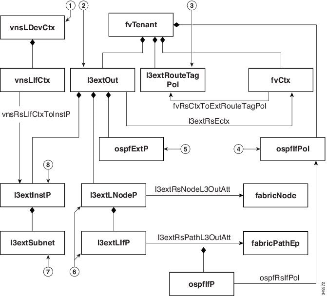
To configure route peering, you must first create one or more l3extOut policies and deploy them on the fabric leaf nodes where the service device is connected. These l3extOut policies specify the Open Shortest Path First (OSPF) parameters that you must enable on the fabric leaf. The policies are very similar to the l3extOut policies that are used for external communication. The following figure illustrates the route peering object relations.
-
vnsLDevCtx—Device selection policy.
-
l3extOut—Contains all OSPF policies for a single area.
-
l3extRouteTagPol—Every context used by route peering needs a unique route tag to avoid OSPF loops. The OSPF routes that are learned from one leg will not be learned on the other leg unless the route tags are different.
-
ospfIfPol—OSPF per interface policy.
-
ospfExtP—OSPF per area policy.
-
l3extLNodeP/l3extLIfP—The nodes or ports on which this l3extOut is deployed.
-
l3extSubnet—Subnets to export from or import into the fabric.
-
l3extInstP—Prefix-based EPG.
Two example l3extOut policies, OspfExternal and OspfInternal, are shown below. These policies are deployed on the external and internal legs of the firewall device in Figure 1. The l3extOut policy specifies one or more prefix-based EPGs (l3extInstP), which control how traffic is classified by the fabric leaf and also how routes are imported from and exported to the service device. The l3extOut policy contains the OSPF per-area policy (ospfExtP) and one or more OSPF interface policies (ospfIfPol) that are specified under it.
The following example shows an OSPF area with area-Id being configured with a value of "100":
<ospfExtP areaId="100" areaType="regular" areaCtrl="redistribute"/>
The area type is set to "regular" and the area control attribute is set to "redistribute".
The OSPF interface policy specifies one or more OSPF interface timers:
<ospfIfPol name="ospfIfPol" ctrl="mtu-ignore" nwT="bcast" xmitDelay="1" helloIntvl="10"
  deadIntvl="40" status="created,modified"/>
If default timers are fine, then you do not need to specify this policy. This policy allows certain timers to be modified from default values and is associated with one or more interfaces by using the following relation:
<13extRsPathL3OutAtt tDn="topology/pod-l/paths-101/pathep-[eth1/25]" ifInstT="ext-svi"
  encap="vlan-3844" addr="30.30.30.100/28" mtu="1500"/>
The attributes of the 13extRsPathL3OutAtt relation are as follows:
-
ifInstT—The logical interface type, which is typically "ext-svi".
-
encap—You must specify a VLAN encapsulation when creating this interface. The encapsulation is pushed to the service device.
-
addr— The IP address of the SVI interface that was created on the fabric leaf where this l3extOut is deployed.
The following policy controls where the l3extOut policy is deployed:
<13extNodeP name="bLeaf-101">
  <13extRsNodeL30utAtt tDn="topology/pod-l/node-101" rtrId="180.0.0.11"/>
  <13extLIfP name="portlf">
    <13extRsPathL30utAtt tDn="topology/pod-1/paths-101/pathep-teth1/251"
      ifInstT="ext-svi" encap="vlan-3844" addr="30.30.30.100/28" mtu="1500"/>
    <ospfIfP authKey="tecom" authType="md5" authKeyId='1'>
      <ospfRslfPol tnOspfIfPolName="ospfIfPol"/>
    </ospflfP>
  </13extLIfP>
</13extLNodeP>
The l3extOut policy must be deployed to the same leaf ports to which the service device is connected.
The scope=import-security attribute does the following things:
-
Controls the flow of traffic in the data plane
-
Acts as a directive to the external device to advertise this route
Note | For route peering to work correctly, the l3extRsPathL3OutAtt relation must point to the same fabric destination as the RsCIfPathAtt relation under the vnsCDev that represents the device. |
OspfExternal Policy
<polUni>
  <fvTenant name="common">
    <fvCtx name="commonctx">
      <fvRsCtxToExtRouteTagPol tnL3extRouteTagPolName="myTagPol"/>
    </fvCtx>
    <l3extRouteTagPol tag="212" name="myTagPol"/>
    <l3extOut name="OspfExternal" status="created,modified">
      <l3extLNodeP name="bLeaf-101">
        <l3extRsNodeL3OutAtt tDn="topology/pod-1/node-101" rtrId="180.0.0.8/28"/>
        <l3extLIfP name="portIf">
          <l3extRsPathL3OutAtt tDn="topology/pod-1/paths-101/pathep-[eth1/23]"
            ifInstT="ext-svi" encap="vlan-3843" addr="40.40.40.100/28" mtu="1500"/>
          <ospfIfP authKey="tecom" authType="md5" authKeyId='1'>
            <ospfRsIfPol tnOspfIfPolName="ospfIfPol"/>
          </ospfIfP>
        </l3extLIfP>
      </l3extLNodeP>
      <ospfExtP areaId="100" areaType="regular" areaCtrl="redistribute"/>
      <l3extInstP name="ExtInstP">
        <l3extSubnet ip="40.40.40.100/28" scope="import-security"/>
        <l3extSubnet ip="10.10.10.0/24" scope="import-security"/>
      </l3extInstP>
      <l3extRsEctx tnFvCtxName="commonctx"/>
    </l3extOut>
    <ospfIfPol name="ospfIfPol" ctrl="mtu-ignore" nwT="bcast" xmitDelay="1" helloIntvl="10"
      deadIntvl="40" status="created,modified"/>
  </fvTenant>
</polUni>
<polUni>
  <fvTenant name="tenant1">
    <l3extRouteTagPol tag="213" name="myTagPol"/>
    <fvCtx name="tenant1ctx1">
      <fvRsCtxToExtRouteTagPol tnL3extRouteTagPolName="myTagPol"/>
    </fvCtx>
    <l3extOut name="OspfInternal" status="created,modified">
      <l3extLNodeP name="bLeaf-101">
        <l3extRsNodeL3OutAtt tDn="topology/pod-1/node-101" rtrId="180.0.0.11"/>
        <l3extLIfP name="portIf">
          <l3extRsPathL3OutAtt tDn="topology/pod-1/paths-101/pathep-[eth1/25]"
            ifInstT="ext-svi" encap="vlan-3844" addr="30.30.30.100/28" mtu="1500"/>
          <ospfIfP authKey="tecom" authType="md5" authKeyId='1'>
            <ospfRsIfPol tnOspfIfPolName="ospfIfPol"/>
          </ospfIfP>
        </l3extLIfP>
      </l3extLNodeP>
      <ospfExtP areaId="100" areaType="regular" areaCtrl="redistribute"/>
      <l3extInstP name="IntInstP">
        <l3extSubnet ip="30.30.30.100/28" scope="import-security"/>
        <l3extSubnet ip="20.20.20.0/24" scope="import-security"/>
      </l3extInstP>
      <l3extRsEctx tnFvCtxName="tenant1ctx1"/>
    </l3extOut>
    <ospfIfPol name="ospfIfPol" ctrl="mtu-ignore" nwT="bcast" xmitDelay="1" helloIntvl="10"
      deadIntvl="40" status="created,modified"/>
  </fvTenant>
</polUni>
The OspfExternalInstP policy specifies that prefixes 40.40.40.100/28 and 10.10.10.0/24 must be used for prefix-based endpoint association. The policy also instructs the fabric to export prefix 20.20.20.0/24 to the service device.
      <13extInstP name="OspfExternalInstP">
        <13extSubnet ip="40.40.40.100/28" scope="import-security"/>
        <13extSubnet ip="10.10.10.0/24" scope="import-security"/>
        <13extSubnet ip="20.20.20.0/24" scope="export"/>
      </13extInstP>
The bleaf-101 policy controls where this l3extOut policy is deployed.
      <l3extLNodeP name="bLeaf-101">
        <l3extRsNodeL3OutAtt tDn="topology/pod-1/node-101" rtrId="180.0.0.8/28"/>
        <l3extLIfP name="portIf">
          <l3extRsPathL3OutAtt tDn="topology/pod-1/paths-101/pathep-[eth1/23]"
            ifInstT="ext-svi" encap="vlan-3843" addr="40.40.40.100/28" mtu="1500"/>
          <!-- <ospfIfP authKey="tecom" authType="md5" authKeyId='1'> -->
          <ospfIfP>
            <ospfRsIfPol tnOspfIfPolName="ospfIfPol"/>
          </ospfIfP>
        </l3extLIfP>
      </l3extLNodeP>
You can deploy virtual services with route peering, although the l3extRsPathL3OutAtt validation with the vnsCIf object is not performed. The datapath will work only if the l3extOut object is deployed to the correct leaf to which the virtual service device is connected.
Border Gateway Protocol Policies
You can configure route peering using internal Border Gateway Protocol (iBGP) on the device’s external interface and static routes on the internal interface. You cannot configure iBGP on both the internal and external interfaces of the device without extra configuration, as the interfaces must be in different autonomous systems and inter-autonomous system redistribute policies do not get pushed down.
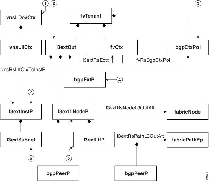
The following figure illustrates the route peering object relations:
-
vnsLDevCtx—Device selection policy.
-
l3extOut—Contains all BGP policies for a single autonomous system.
-
bgpCtxPol—Per-context BGP timers.
-
bgpExtP—BGP per ASN policy.
-
l3extLIfP/l3extLNodeP—Controls to which nodes or ports these endpoint groups (EPGs) are deployed.
-
l3extSubnet—Subnets to export from and import into the fabric.
-
l3extInstP—Prefix-based EPG.
The following policy configures iBGPv4/v6 on the external interface:
<polUni>
  <fvTenant name="common">
    <fvCtx name="commonctx">
      <fvRsBgpCtxPol tnBgpCtxPolName="timer-3-9"/>
      <fvRsCtxToExtRouteTagPol tnL3extRouteTagPolName="myTagPol"/>
    </fvCtx>
    <l3extRouteTagPol tag="212" name="myTagPol"/>
    <bgpCtxPol grCtrl="helper" holdIntvl="9" kaIntvl="3" name="timer-3-9" staleIntvl="30"/>
    <l3extOut name="BgpExternal" status="created,modified">
      <l3extLNodeP name="bLeaf-101">
        <!-- <bgpPeerP addr="40.40.40.102/32 "ctrl="send-com"/> -->
        <l3extRsNodeL3OutAtt tDn="topology/pod-1/node-101" rtrId="180.0.0.8/28>"
          <l3extLoopBackIfP addr="50.50.50.100/32"/>
        </l3extRsNodeL3OutAtt>
        <l3extLIfP name="portIf">
          <l3extRsPathL3OutAtt tDn="topology/pod-1/paths-101/pathep-[eth1/23]"
            ifInstT="ext-svi" encap="vlan-3843" addr="40.40.40.100/28 "mtu="1500">
            <bgpPeerP addr="40.40.40.102/32 "ctrl="send-com"/>
          </l3extRsPathL3OutAtt>
        </l3extLIfP>
      </l3extLNodeP>
      <bgpExtP/>
      <l3extInstP name="ExtInstP">
        <l3extSubnet ip="40.40.40.100/28 "scope="import-security"/>
        <l3extSubnet ip="10.10.10.0/24 "scope="import-security"/>
        <l3extSubnet ip="20.20.20.0/24 "scope="export-rtctrl"/>
      </l3extInstP>
      <l3extRsEctx tnFvCtxName="commonctx"/>
    </l3extOut>
  </fvTenant>
</polUni>
iBGP peers can be configured at the physical interface level or the loopback level. The following example shows a iBGP peer configured at the physical interface level:
<l3extLIfP name="portIf">
          <l3extRsPathL3OutAtt tDn="topology/pod-1/paths-101/pathep-[eth1/23]"
            ifInstT="ext-svi" encap="vlan-3843" addr="40.40.40.100/28 "mtu="1500">
            <bgpPeerP addr="40.40.40.102/32 "ctrl="send-com"/>
          </l3extRsPathL3OutAtt>
</l3extLIfP>
In this case, the iBGP process that is running on the fabric uses the switch virtual interface (SVI) IP address 40.40.40.100/28 to peer with its neighbor. The neighbor is the service device at IP address 40.40.40.102/32.
In the following example, the iBGP peer definition has been moved to the logical node level (under l3extLNodeP) and a loopback interface has been configured:
      <l3extLNodeP name="bLeaf-101">
        <bgpPeerP addr="40.40.40.102/32 "ctrl="send-com"/>
        <l3extRsNodeL3OutAtt tDn="topology/pod-1/node-101" rtrId="180.0.0.8/28>"
          <l3extLoopBackIfP addr="50.50.50.100/32"/>
        </l3extRsNodeL3OutAtt>
        <l3extLIfP name="portIf">
          <l3extRsPathL3OutAtt tDn="topology/pod-1/paths-101/pathep-[eth1/23]"
            ifInstT="ext-svi" encap="vlan-3843" addr="40.40.40.100/28 "mtu="1500">
          </l3extRsPathL3OutAtt>
        </l3extLIfP>
      </l3extLNodeP>
In this case, the iBGP process uses the loopback address to peer with its neighbor. If no loopback is configured, then the fabric uses the IP address that is specified by rtrId to peer with the neighbor.
In such cases, the device needs a route to reach the SVI. This is typically configured using graph parameters, as shown by the following example for ASA, where IP address 50.50.50.0 is reachable from IP address 40.40.40.100:
<vnsAbsFolder name="ExtRouteCfg" key="StaticRoute">
              <vnsAbsFolder name="route1" key="route">
                <vnsAbsParam name="network" key="network" value="50.50.50.0"/>
                <vnsAbsParam name="netmask" key="netmask" value="255.255.255.0"/>
                <vnsAbsParam name="gateway" key="gateway" value="40.40.40.100"/>
              </vnsAbsFolder>
              <vnsAbsFolder name="route2" key="ipv6_route">
                <vnsAbsParam name="prefix" key="prefix" value="2005::/64"/>
                <vnsAbsParam name="gateway" key="gateway" value="2004::2828:2866"/>
              </vnsAbsFolder>
</vnsAbsFolder>
The following example shows static route configuration on the fabric for the internal interface of the device:
<polUni>
  <fvTenant name="tenant11">
    <l3extOut name="StaticInternal" status="created,modified">
      <l3extLNodeP name="bLeaf-201">
        <l3extRsNodeL3OutAtt tDn="topology/pod-1/node-101" rtrId="180.0.0.11>"
          <ipRouteP ip="20.20.20.0/24>"
            <ipNexthopP nhAddr="30.30.30.102/32"/>
          </ipRouteP>
        </l3extRsNodeL3OutAtt>
        <l3extLIfP name="portIf">
          <l3extRsPathL3OutAtt tDn="topology/pod-1/paths-101/pathep-[eth1/25]"
            ifInstT="ext-svi" encap="vlan-3844" addr="30.30.30.100/28 "mtu="1500"/>
        </l3extLIfP>
      </l3extLNodeP>
      <l3extInstP name="IntInstP">
        <l3extSubnet ip="20.20.20.0/24 "scope="import-security"/>
      </l3extInstP>
      <l3extRsEctx tnFvCtxName="tenant1ctx1"/>
    </l3extOut>
  </fvTenant>
</polUni>
Selecting an L3extOut Policy for a Cluster
A specific l3extOut policy can be associated with a logical device's interface using its selection policy vnsLIfCtx. The following example shows how this is achieved:
<vnsLDevCtx ctrctNameOrLbl="webCtrct1" graphNameOrLbl="WebGraph" nodeNameOrLbl="FW">
  <vnsRsLDevCtxToLDev tDn="uni/tn-tenant1/lDevVip-Firewall"/>
  <vnsRsLDevCtxToRtrCfg tnVnsRtrCfgName="FwRtrCfg"/>
  <vnsLIfCtx connNameOrLbl="internal">
	   <vnsRsLIfCtxToInstP tDn="uni/tn-tenant1/out-OspfInternal/instP-IntInstP"
      status="created,modified"/>
  	 <vnsRsLIfCtxToLIf tDn="uni/tn-tenant1/lDevVip-Firewall/lIf-internal"/>
  </vnsLIfCtx>
  <vnsLIfCtx connNameOrLbl="external">
    <vnsRsLIfCtxToInstP tDn="uni/tn-common/out-OspfExternal/instP-ExtInstP"
      status="created,modified"/>
    <vnsRsLIfCtxToLIf tDn="uni/tn-tenant1/lDevVip-Firewall/lIf-external"/>
  </vnsLIfCtx>
</vnsLDevCtx>
The vnsRsLIfCtxToInstP relation is used to select a particular prefix-based EPG that (l3extInstP) is associated with this leg of the service device. You can specify the redistribute protocol redistribute property on this relation. The default value for the redistribute property is "ospf,bgp". Leaving redistribute at the default value causes the Application Policy Infrastructure Controller (APIC) to auto-detect the routing protocols that are configured on each leg and push the appropriate redistribute settings. The automatic settings always redistribute from an interior gateway protocol (OSPF) to an exterior gateway protocol (BGP).
If you want to use a specific redistribute setting, such as static or connected, then you can add those settings to this relation. For example, redistribute="ospf,bgp,static" causes the auto-detected settings and redistribute-static to be pushed to the service device.
Setting this property to a specific value that does not include the defaults, such as redistribute="ospf,static,connected", causes those exact settings to be pushed to the service device. This is useful in scenarios in which you want to override the defaults that are chosen by the APIC.
Note | The relation points to an EPG (l3extInstP) and not to the l3extOut itself, as there can be multiple such EPGs under an l3extOut policy, and different device selection policies could point to those EPGs. This allows for fine control of which prefixes are imported or exported by different service graphs. |
The vnsRsLDevCtxToRtrCfg relation is used to select a particular vnsRtrCfg policy for this device selector. vnsRtrCfg policies are needed to specify the router ID that is used by routing protocols, such as Open Shortest Path First (OSPF) or internal Border Gateway Protocol (iBGP), and must be supplied by the user. This router ID is sent to the device.
The following code is an example vnsRtrCfg policy:
<vnsRtrCfg name="FwRtrCfg" rtrId="180.0.0.10”/>
The associated concrete device must have a vnsRsCIfPathAtt object, which deploys the device to the same fabric leaf as shown below:
<vnsCDev name="ASA">
  <vnsCIf name="Gig0/0">
    <vnsRsCIfPathAtt tDn="topology/pod-1/paths-101/pathep-[eth1/23]"/>
  </vnsCIf>
  <vnsCIf name="Gig0/1">
    <vnsRsCIfPathAtt tDn="topology/pod-1/paths-101/pathep-[eth1/25]"/>
  </vnsCIf>
  <vnsCMgmt name="devMgmt" host="{{asaIp}}" port="443"/>
  <vnsCCred name="username" value="admin"/>
  <vnsCCredSecret name="password" value="insieme"/>
</vnsCDev>
Note | When route peering is configured, you do not need to configure bridge domains on the vnsLIfCtx selectors. Attempting to configure both bridge domain relations (vnsRsLIfCtxToBD) and l3extInstP relations (vnsRsLIfCtxToInstP) will result in a fault. |
Route Peering End-to-End Flow
The following figure shows how route peering works end-to-end.
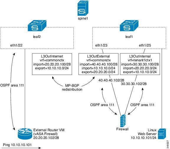
The figure shows an example two leaf, single spine topology where a Linux web server's IP address is advertised to an external router using route peering. The Linux web server is at IP address 10.10.10.101/24 and is hosted on an ESX server that is connected to leaf1. A regular bridge domain-based endpoint group (EPG) is deployed to represent traffic that originates from the web server.
You deploy a service graph that comprises a two-arm routable firewall, with both arms being connected to leaf1. There is a virtual routing and forwarding (VRF)-split on the firewall device, meaning that each arm of the firewall is connected to the leaf in a different VRF (context). The VRF-split is necessary to ensure that traffic is routed through the service device, rather than being short-circuited by the leaf. The external traffic is represented by an l3extOut (L3OutInternet) that is deployed on leaf2. leaf2 can be viewed as a fabric border-leaf in this scenario. You deploy a contract between L3OutInternet and the web server EPG. This contract is associated with a service graph that encompasses the firewall device.
To publish the web server route to the external world, you deploy two l3extOuts—L3OutExternal and L3OutInternal—to the leaf ports to which the service device is connected. As a result, Open Shortest Path First (OSPF) peering sessions are established between the leaf and the firewall in both of the contexts (commonctx and tenant1ctx1). The export attribute on these l3extOuts control how the routing information is advertised to the border leaf. Routes are exchanged internally between the fabric leaves using Multiprotocol Border Gateway Protocol (MP-BGP) redistribution.
Ultimately, the web server route is advertised to the external router (IP address 20.20.20.102) using a separate OSPF session. This results in the external router being able to ping the web server without any manual static route configuration.
Cisco Application Centric Infrastructure Fabric Serving As a Transit Routing Domain
You can deploy the Cisco Application Centric Infrastructure (ACI) fabric as a transit routing domain, which is useful when the ACI point of delivery (POD) serves as a transit routing domain between other PODs. In the following illustration, two external l3extOuts—L3OutInternet and L3OutInternet2—are deployed on two border leaves. There is a contract associated between these l3extOuts, and the contract is attached to a single node service graph containing a firewall service device.
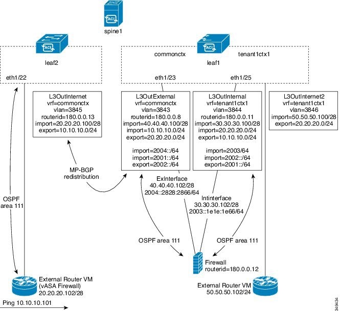
Two additional l3extOuts are deployed on the external and internal legs of the firewall device to establish Open Shortest Path First (OSPF) peering sessions between them. By appropriately configuring the import security control (the import-security attribute), you can control which routes are allowed to transit the ACI fabric to the border leaves.
Configuring Route Peering Using the GUI
You must perform the following tasks to configure route peering:
-
Create a static VLAN pool that will be used for the encapsulation VLAN between the device and the Cisco Application Centric Infrastructure (ACI) fabric.
-
Create an external routed domain that will tie together the location (leaf node/path) of the device and the VLAN pool.
-
Create an external routed network, which is used to specify the routing configuration in the ACI fabric for route peering.
-
Create a new router configuration to specify the router ID that will be used on the device.
-
Create a service graph association, which involves associating the external routed network policy and router configuration with a device selection policy.
- Creating a Static VLAN Pool Using the GUI
- Creating an External Routed Domain Using the GUI
- Creating an External Routed Network Using the GUI
- Creating a Router Configuration Using the GUI
- Creating a Service Graph Association Using the GUI
Creating a Static VLAN Pool Using the GUI
Before creating an external routed network configuration, you must create a static VLAN pool that will be used for the encapsulation VLAN between the device and the fabric.
Creating an External Routed Domain Using the GUI
You must create an external routed domain that ties together the location (leaf node/path) of the device and the static VLAN pool that you created for route peering.
Creating an External Routed Network Using the GUI
The external routed network specifies the routing configuration in the Cisco Application Centric Infrastructure (ACI) fabric for route peering.
| Step 1 | On the menu bar, choose . |
| Step 2 | In the Work pane, double click the tenant's name. |
| Step 3 | In the Navigation pane, choose . |
| Step 4 | In the Work pane, choose . |
| Step 5 | In the
Create
Routed Outside dialog box, fill in the fields as required, except as
specified below:
|
| Step 6 | In the Create Node Profile dialog box, fill in the fields as required, except as specified below: |
| Step 7 | In the
Select
Node dialog box, fill in the fields as required, except as specified
below:
|
| Step 8 | In the Create Static Route dialog box, fill in the fields as required, except as specified below: |
| Step 9 | Click OK. |
| Step 10 | In the Select Node dialog box, click OK. |
| Step 11 | If you are using BGP as the dynamic routing protocol with the device, in the BGP Peer Connectivity Profiles section, click +. Otherwise, go to step Step 14. |
| Step 12 | In the Create Peer Connectivity Profile dialog box, fill in the fields as required, except as specified below: |
| Step 13 | In the Create Peer Connectivity Profile dialog box, click OK. |
| Step 14 | In the Interface Profiles section, click +. |
| Step 15 | In the Create Interface Profile dialog box, fill in the fields as required. |
| Step 16 | In the Interface section, choose the SVI tab. |
| Step 17 | In the Interface section, click +. |
| Step 18 | In the
Select
SVI Interface dialog box, fill in the fields as required, except as
specified below:
|
| Step 19 | Click OK. |
| Step 20 | In the Create Interface Profile dialog box, click OK. |
| Step 21 | In the Create Node Profile dialog box, click OK. |
| Step 22 | In the Create Routed Outside dialog box, click Next. |
| Step 23 | In the External EPG Networks section, click +. |
| Step 24 | In the Create External Network dialog box, fill in the fields as required, except as specified below: |
| Step 25 | In the
Create
Subnet dialog box, fill in the fields as required, except as
specified below:
|
| Step 26 | Click OK. |
| Step 27 | (Optional) Create additional subnets as needed. |
| Step 28 | In the Create External Network dialog box, click OK. |
| Step 29 | In the Create Routed Outside dialog box, click Finish. |
Creating a Router Configuration Using the GUI
As part of the routing protocol configuration, you must specify the router ID that will be used on the device.
Creating a Service Graph Association Using the GUI
You must create a service graph association, which involves associating the external routed network policy and router configuration with a device selection policy.
The following changes occur:
-
The encapsulation VLAN for the interface that is associated with the external routed network is reprogrammed to match the VLAN that is configured as part of the external routed network interface profile
-
The external routed network interface and routing protocol configuration is pushed to the leaf switch
-
The routing protocol configuration is pushed to the device using the device package
Configuring Route Peering Using the NX-OS-Style CLI
This section provides example commands of using the NX-OS-style CLI to configure route peering.
For the complete configuration for Layer 3 external connectivity (Layer 3 outside) using the named mode, including routing protocols (BGP, OSPF) and route maps, see the Cisco APIC NX-OS Style CLI Command Reference document.
Note | The external Layer 3 configuration in the CLI is available in two modes: basic mode and named mode. For a given tenant or VRF, user only one of these modes for all external Layer 3 configuration. Route peering is supported only in the named mode. |
Troubleshooting Route Peering
If your Cisco Application Centric Infrastructure (ACI) fabric has a route peering or data traffic issue, there are several commands that you can run on ACI fabric leaves to troubleshoot the issue.
The following table provides troubleshooting commands that you can run in the switch shell on the fabric leaf.
|
Command |
Description |
|---|---|
|
show ip route vrf all |
Displays all of the routes in a particular context, including dynamically learned routes. |
|
show ip ospf neighbor vrf all |
Displays Open Shortest Path First (OSPF) peering sessions with neighboring devices. |
|
show ip ospf vrf all |
Displays the run-time OSPF configuration in each context. |
|
show ip ospf traffic vrf all |
Examines OSPF traffic on each virtual routing and forwarding (VRF) context. |
|
show system internal policymgr stats |
Displays the contract filter rules on a particular leaf and examines the packet hit counts on the rules. |
The following table provides a troubleshooting command that you can run in the vsh_lc shell.
|
Command |
Description |
|---|---|
|
show system internal aclqos prefix |
Examines the IPv4 prefix association rules on a particular leaf and the traffic hit counts on the rules. |
In addition to the shell commands, you can check the following things to help with troubleshooting:
Verifying the Leaf Switch Route Peering Functionality Using the CLI
You can use switch shell commands on the fabric leaf to verify the leaf switch configuration and route peering functionality.
 Feedback