- Preface
- New and Changed Information
- Overview
- Importing a Device Package
- Defining a Logical Device
- Configuring Connectivity to Devices
- Selecting a Layer 4 to Layer 7 Device to Render a Graph
- Configuring a Service Graph
- Configuring Route Peering
- Configuring Direct Server Return
- Configuring the Device and Chassis Manager
- Configuring Unmanaged Mode
- Configuration Parameters
- Using a Service Graph Template
- Monitoring a Service Graph
- Configuring Administrator Roles for Managing a Service Configuration
- Developing Automation
- Using the GUI
- About Direct Server Return
- Direct Server Return Architecture
- Example XML POST of Direct Server Return for Static Service Deployment
- Direct Server Return for Static Service Deployment
- Direct Server Return for Service Graph Insertion
- Configuring the Citrix Server Load Balancer for Direct Server Return
- Configuring a Linux Server for Direct Server Return
Configuring Direct
Server Return
About Direct Server Return
The direct server return feature enables a server to respond directly to clients without having to go through the load balancer, which eliminates a bottleneck in the server-to-client path. In traditional load balancer deployments, the load balancer is in the path of the client-to-server communication: both the client-to-server request path and the server-to-client response path. While the amount of data in the requests from the client-to-server direction are relatively small, the server-to-client response traffic is much higher: approximately 10 times that of client-to-server request data. The load balancer in the path of this high volume response traffic becomes a bottleneck and adversely affects the communication.
For direct server return deployments, a virtual IP address is shared by the load balancer and server. Clients always address their request to the virtual IP address that is intended to reach the load balancer, and the direct response from the server-to-client use this virtual IP address as the source address. Cisco Application Centric Infrastructure (ACI) enabled with data-path learning of the IP source address poses problems when it learns the virtual IP address from the server-to-client traffic, leading to the disruption of Client-to-load balancer request traffic. To allow for the proper operation of a direct server return deployment, the ACI fabric must ensure that the request-response traffic between the communicating endpoints are delivered to their intended destination correctly. This requires that the data-path IP address learning on the leafs must be controlled in such a way that there is no interruption to client-to-load balancer, load balancer-to-server, and server-to-client traffic.
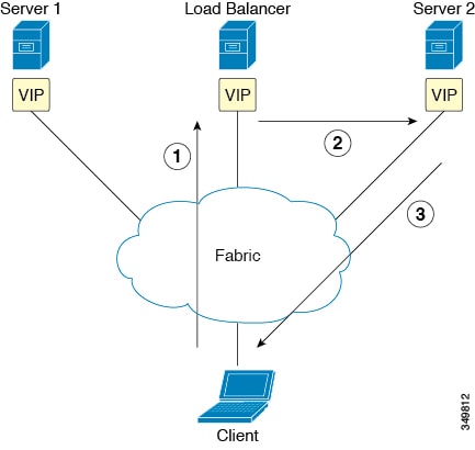
The following figure illustrates the data path in a direct server return deployment:
-
The load balancer and all of the back-end servers are configured with the virtual IP address. The load balancer alone responds to Address Resolution Protocol (ARP) requests for this virtual IP address. After load balancing the client request, the load balancer re-writes the destination MAC address in the packet and forwards the MAC address to one of the back-end servers.
-
The virtual IP address is configured on the back-end server, but ARP is disabled to prevent back-end servers from responding to ARP requests for this virtual IP address.
-
The server sends the return traffic directly to the client, by-passing the load-balancer.
- Layer 2 Direct Server Return
- About Deploying Layer 2 Direct Server Return with Cisco Application Centric Infrastructure
- Supported Direct Server Return Configuration
Layer 2 Direct Server Return
Layer 2 direct server return is the common or traditional deployment, also known as direct routing, SwitchBack, or nPath. In this deployment, the virtual IP address is shared by the load balancer and server. The load balancers and servers must be layer 2 adjacent. A layer 2 direct server return deployment has the following limitations:
-
You lose flexibility in server placement
-
You need an extra server configuration to suppress Address Resolution Protocol (ARP) responses to client virtual IP address requests
-
Port selection is layer 3 and protocol dependent; port selection cannot happen at layer 2 (load balancer to server communication)
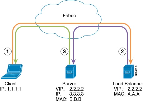
A layer 2 direct server return deployment has the following traffic flow:
-
Client to load balancer
Source IP Address
1.1.1.1
Destination IP Address
2.2.2.2
Destination MAC Address
A.A.A
-
Load balancer to server
Source IP Address
1.1.1.1
Destination IP Address
2.2.2.2
Destination MAC Address
B.B.B
-
Server to client
Source IP Address
2.2.2.2
Destination IP Address
1.1.1.1
Destination MAC Address
MAC address of the default gateway
About Deploying Layer 2 Direct Server Return with Cisco Application Centric Infrastructure
The following information applies to deploying layer 2 direct server return with Cisco Application Centric Infrastructure (ACI):
-
The virtual IP address (2.2.2.2) moves within the ACI fabric
-
The load balancer-to-server and server-to-client traffic with the same source virtual IP address (2.2.2.2)
-
The server-to-client traffic is routed; the traffic is addressed to the gateway MAC address in the fabric
-
The data-path learning of the source IP address from the server moves to the virtual IP address within the fabric
-
-
There are no issues for the client IP address (1.1.1.1) appearing from difference sources
-
The client IP address appears as the source IP address from both the client and the load balancer in the fabric
-
The load balancer and server are layer 2 adjacent and the load balancer-to-server traffic is layer 2 forwarded
-
There is no data-path IP address learning from layer 2 forwarded traffic in the fabric
-
Even if the client IP address appears as the source IP address from the load balancer in the fabric, the client IP address is not learned
-
Supported Direct Server Return Configuration
The following figure illustrates the supported direct server return configuration:
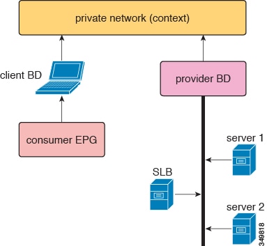
The following information applies to the supported configuration:
- The server load balancer and servers are in the same subnet and bridge domain
- The server load balancer should operate in 1 ARM mode; the inside and outside legs of server load balancer should point to the same bridge domain
- The consumer and provider endpoint groups should be under the same private network; no shared service configuration is supported
Direct Server Return Architecture
To enable layer 2 direct server return, the virtual IP address that is shared by the load balancer and server can be configured as static within the fabric on the tenant Virtual Routing and Forwarding (VRF). With the virtual IP address being static, the data-path learning of this virtual IP address is prevented. The switch side end-point-manager design handles the static configuration from the policy engine in the form of a {VRF, VIP, S-Class} tuple in the concrete model. While there are no architectural changes to the endpoint manager (EPM), endpoint manager client (EPMC), and forwarding silicon, there are changes in all of these layers to allow and maintain the virtual IP address static configuration. The architecture allows for both virtual IPv4 and virtual IPv6 static configurations. Other than the address parsing and initial setup, architecturally and design-wise, both virtual IPv4 and virtual IPv6 are handled with the same code paths.
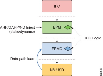
The direct server return design flow and configuration flow is part of the EPM/EPMC/USD flow. The flow for this exists only from Northbound-to-Southbound; that is, . The forwarding silicon in this case is North Star, as only the North Star local station table is touched for this purpose. The same endpoint create/modify/delete flow is used with the extra static IP address endpoint flag.
All of the learn requests for any new IP address endpoint goes through a static virtual IP address endpoint check. When the learning/processing request is for the already-existing {VRF, VIP, S-class} tuple, any modification pre-processing is handled by the direct server return pre-processing code and is handled back with the proper flags to generic endpoint processing.
The following list provides a high level view of the direct server return design points:
-
All virtual IPv4 and virtual IPv6 add/modify/delete configurations are handled by the endpoint manager
-
The EPM and EPMC install the full (32 or /128) virtual IP address in the North Star local station table source address
- The EPM allows for the discovery of a load balancer endpoint through ARP/GARP/ND IP-MAC binding and MAC learning
- The EPM and EPMC prevent spurious North Star data-path learning of the {VRF, VIP} tuple.
- The EPM and EPMC disallow IP-MAC binding association when the learned entry S-class mismatches with the {VRF, VIP, S-class} tuple that is configured in the policy engine; this is applicable to both the ARP/GARP/ND path and the data-path learning path
- The EPM does not alter the discovery dissemination of a load balancer (through ARP/GARP/ND) to COOP
- During configuration, the EPM and EPMC clean up the existing learned entry (ARP/GARP/ND) when the entry's S-class does not match
- When configuring the virtual IP address, the EPM and EPMC always clean up the existing entry for the same {VRF, VIP} tuple that was created through data-path learning
- ARP/ND/MAC aging is not touched by these changes, but the EPM and EPMC ensure that unless there is a configuration delete for the {VRF, VIP} tuple, the static entry maintained in the local station table is never deleted
- The implementation of this feature takes the approach of keeping the {VRF, VIP} tuple entry learned through ARP/GARP/ND when the same entry configuration comes from policy engine, rather than deleting the existing entry; this is only when the existing entry's S-class is same as the configured entry S-class. This approach is taken to avoid the fabric wide churn that would otherwise happen due to the deletion of the entry
- The S-class and other information related to the entry is kept as part of the IP address information; that is, the information is kept at the endpoint's IP address level, not at the endpoint level
-
When there is a overlap between the {BD, Prefix of virtual IP, S-class} tuple and the policy engine-configured {VRF, VIP, S-class} tuple, precedence is given to the {VRF, virtual IP, S-class} tuple
Example XML POST of Direct Server Return for Static Service Deployment
The following XML POST is an example of direct server return static service deployment:
<fvAp name="dev">
      <fvAEPg name="loadbalancer">
        <fvRsDomAtt tDn="uni/phys-{{tenantName}}"/>
        <fvRsBd tnFvBDName="lab"/>
        <fvVip addr="121.0.0.{{net}}" />
        <fvRsPathAtt tDn="topology/pod-1/paths-104/pathep-[eth1/1]" encap="vlan-33" />
        <fvRsProv tnVzBrCPName="loadBalancer"/>
        <fvRsCons tnVzBrCPName="webServer"/>
      </fvAEPg>
        <fvAEPg name="webServer">
          <fvRsDomAtt tDn="uni/phys-{{tenantName}}"/>
            <fvRsBd tnFvBDName="lab"/>
          <fvRsPathAtt tDn="topology/pod-1/paths-101/pathep-[eth1/1]" encap="vlan-34"/>
            <fvRsProv tnVzBrCPName="webServer"/>
        </fvAEPg>
      <fvAEPg name="client">
        <fvRsDomAtt tDn="uni/phys-{{tenantName}}"/>
        <fvRsBd tnFvBDName="lab"/>
        <fvRsPathAtt tDn="topology/pod-1/paths-103/pathep-[eth1/4]" encap="vlan-1114"/>
        <fvRsCons tnVzBrCPName="loadBalancer"/>
      </fvAEPg>
</fvAp>
The direct server return configuration is downloaded to all of the top-of-rack switches (ToR) where the toEPG contract exists for the Web server. In the example, the direct server return virtual IP address configuration will be downloaded to the ToR denoted "paths-101". You should not see a static configuration of the virtual IP address downloaded on ToR that is denoted by node-ID 104.
The direct server return configuration can be issued without the existence of the toEPG contract. Whenever the contract is created, the direct server return virtual IP address, if already configured, will be automatically downloaded to the ToR where the Web server toEPG contract exists.
Direct Server Return for Static Service Deployment
In the static service deployment mode, you configure the service flow by creating the appropriate application endpoint groups and contracts on a hop-by-hop basis.
Direct Server Return for Static Service Deployment Logical Model
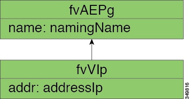
You can configure the virtual IP addresses that are used by the load balancers by using the fvVip object under an application endpoint group (fvAEPg).
The following figure illustrates the logical model for static service deployment:
Direct Server Return for Service Graph Insertion
The Cisco Application Centric Infrastructure (ACI) provides automated service insertion by using vendor packages and service graphs. In this mode, the endpoint groups that are created for the service device legs, such as inside and outside endpoint groups, are created by the ACI without the operator configuration.
For service graph insertion, you must configure the virtual IP addresses under the appropriate logical interface context for the service device, as shown in the following example XML POST:
      <vnsLDevCtx ctrctNameOrLbl="webCtrct"
                             graphNameOrLbl="G1"
                             nodeNameOrLbl="SLB">

           <vnsRsLDevCtxToLDev tDn="uni/tn-coke/lDevVip-InsiemeCluster"/>

           <vnsLIfCtx connNameOrLbl="inside">
               <vnsRsLIfCtxToBD tDn="uni/tn-coke/BD-cokeBD1"/>
               <vnsRsLIfCtxToLIf tDn="uni/tn-coke/lDevVip-InsiemeCluster/lIf-inside"/>
           </vnsLIfCtx>

           <vnsLIfCtx connNameOrLbl="outside">
               <vnsRsLIfCtxToBD tDn="uni/tn-coke/BD-cokeBD1"/>
               <vnsRsLIfCtxToLIf tDn="uni/tn-coke/lDevVip-InsiemeCluster/lIf-outside"/>
               <vnsSvcVip addr="9.9.9.9" />
               <vnsSvcVip addr="11.11.11.11" />
           </vnsLIfCtx>
       </vnsLDevCtx>
The sample request configures two virtual IP addresses (9.9.9.9 and 11.11.11.11) on the outside leg of the server load balancer. The virtual IP address definition is under LIfCtx instead of being under an endpoint group as it is with a static direct server return configuration. This is because in the service graph case, operators do not have direct access to an endpoint group for the device legs, unlike with a static service deployment.
Direct Server Return Shared Layer 4 to Layer 7 Service Configuration
When the service device is configured in the common tenant or management tenant, the implicit model differs slightly. Instead of vnsEPpInfo, the service virtual IP address update managed object is created as a child of vnsREPpInfo. One vnsSvcEpgCont managed object is created per vnsRsEPpInfo to keep track of shared SvcVips across tenants.
Configuring the Citrix Server Load Balancer for Direct Server Return
The following procedure provides an overview of how to configure the Citrix server load balancer for direct server return.
Configuring a Linux Server for Direct Server Return
The following procedure provides an overview of how to configure a Linux server for direct server return.
| Step 1 | Configure the
virtual IP addresses on the loopback interfaces by creating the
/etc/sysconfig/network-scripts/ifcfg-lo file in
Centos with the following contents:
DEVICE=lo:1
IPADDRESS=10.10.10.99
NETMASK=255.255.255.255
NETWORK=10.10.10.99
BROADCAST=10.10.10.99
ONBOOT=yes
NAME=loopback
In this example, 10.10.10.99 is the virtual IP address. |
| Step 2 | Set the
arp_ignore and
arp_announce settings in the server interface
that is used to reply to client request:
echo 1 > /proc/sys/net/ipv4/conf/eth1/arp_ignore
echo 2 > /proc/sys/net/ipv4/conf/eth1/arp_announce
In this example, eth1 is the server interface used to respond to client requests. For more information about the ARP settings, see the following Linux Virtual Server wiki page: http://kb.linuxvirtualserver.org/wiki/Using_arp_announce/arp_ignore_to_disable_ARP |
 Feedback