- Preface
- Overview
- Prerequisites
- Importing a Device Package
- Configuring a Device (Logical Device)
- Configuring Connectivity to Devices
- Using a Device
- Configuring a Service Graph
- Configuration Parameters
- Using a Service Graph Template
- Monitoring a Service Graph
- Configuring Administrator Roles for Managing a Service Configuration
- Developing Automation
- Using the GUI Wizards
- About Service Graphs
- About Function Nodes
- About Function Node Connectors
- About Service Graph Connections
- About Terminal Nodes
- About Service Graph Template Configuration Parameters
- Configuring Service Graph Templates Using the GUI
- Creating a Service Graph Template Using the REST APIs
- Configuring a Service Graph Using the NX-OS-Style CLI
Configuring a
Service Graph
- About Service Graphs
- About Function Nodes
- About Function Node Connectors
- About Service Graph Connections
- About Terminal Nodes
- About Service Graph Template Configuration Parameters
- Configuring Service Graph Templates Using the GUI
- Creating a Service Graph Template Using the REST APIs
- Configuring a Service Graph Using the NX-OS-Style CLI
About Service Graphs
The Cisco Application Centric Infrastructure (ACI) treats services as an integral part of an application. Any services that are required are treated as a service graph that is instantiated on the ACI fabric from the Cisco Application Policy Infrastructure Controller (APIC). Users define the service for the application, while service graphs identify the set of network or service functions that are needed by the application.
A service graph represents the network using the following elements:
-
Function node—A function node represents a function that is applied to the traffic, such as a transform (SSL termination, VPN gateway), filter (firewalls), or terminal (intrusion detection systems). A function within the service graph might require one or more parameters and have one or more connectors.
-
Terminal node—A terminal node enables input and output from the service graph.
-
Connector—A connector enables input and output from a node.
-
Connection—A connection determines how traffic is forwarded through the network.
After the graph is configured in the APIC, the APIC automatically configures the services according to the service function requirements that are specified in the service graph. The APIC also automatically configures the network according to the needs of the service function that is specified in the service graph, which does not require any change in the service device.
A service graph is represented as two or more tiers of an application with the appropriate service function inserted between.
A service appliance (device) performs a service function within the graph. One or more service appliances might be required to render the services required by a graph. One or more service functions can be performed by a single-service device.
Service graphs and service functions have the following characteristics:
-
Traffic sent or received by an endpoint group can be filtered based on a policy, and a subset of the traffic can be redirected to different edges in the graph.
-
Service graph edges are directional.
-
Taps (hardware-based packet copy service) can be attached to different points in the service graph.
-
Logical functions can be rendered on the appropriate (physical or virtual) device, based on the policy.
-
The service graph supports splits and joins of edges, and it does not restrict the administrator to linear service chains.
-
Traffic can be reclassified again in the network after a service appliance emits it.
-
Logical service functions can be scaled up or down or can be deployed in a cluster mode or 1:1 active-standby high-availability mode, depending on the requirements.
The following figure provides an example of a service graph deployment:
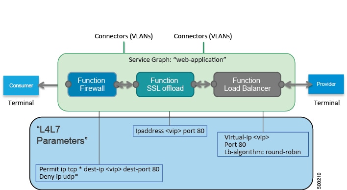
By using a service graph, you can install a service, such as an ASA firewall, once and deploy it multiple times in different logical topologies. Each time the graph is deployed, ACI takes care of changing the configuration on the firewall to enable the forwarding in the new logical topology.
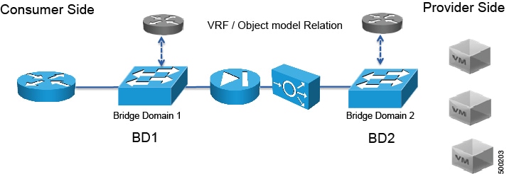
Deploying a service graph requires bridge domains and VRFs, as shown in the following figure:
 Note | If you have some of the legs of a service graph that are attached to endpoint groups in other tenants, when you use the Remove Related Objects of Graph Template function in the GUI, the APIC does not remove contracts that were imported from tenants other than where the service graph is located. The APIC also does not clean endpoint group contracts that are located in a different tenant than the service graph. You must manually remove these objects that are in different tenants. |
About Function Nodes
A function node represents a single service function. A function node has function node connectors, which represent the network requirement of a service function.
A function node within a service graph can require one or more parameters. The parameters can be specified by an endpoint group (EPG), an application profile, or a tenant VRF. Parameters can also be assigned at the time that you define a service graph. The parameter values can be locked to prevent any additional changes.
About Function Node Connectors
A function node connector connects a function node to the service graph and is associated with the appropriate bridge domain and connections based on the graph's connector's subset. Each connector is associated with a VLAN or Virtual Extensible LAN (VXLAN). Each side of a connector is treated as an endpoint group (EPG), and whitelists are downloaded to the switch to enable communication between the two function nodes.
About Service Graph Connections
A service graph connection connects one function node to another function node.
About Terminal Nodes
Terminal nodes connect a service graph with the contracts. You can insert a service graph for the traffic between two application endpoint groups (EPGs) by connecting the terminal node to a contract. Once connected, traffic between the consumer EPG and provider EPG of the contract is redirected to the service graph.
About Service Graph Template Configuration Parameters
A service graph template can have configuration parameters, which are specified by the device package. Configuration parameters can also be specified by an EPG, application profile, or tenant context. A function node within a service graph template can require one or more configuration parameters. The parameter values can be locked to prevent any additional changes.
When you configure a service graph template and specify the values of the configuration parameters, the Application Policy Infrastructure Controller (APIC) passes the parameters to the device script that is within the device package. The device script converts the parameter data to the configuration that is downloaded onto the device.
Configuring Service Graph Templates Using the GUI
You can configure the service graph templates using the GUI.
See Using the GUI for the procedure for configuring the service graph templates.
Creating a Service Graph Template Using the REST APIs
<polUni>
  <fvTenant name="acme">
    <vnsAbsGraph name="G1">
      <vnsAbsTermNodeCon name="Input1">
        <vnsAbsTermConn name="C1">
                </vnsAbsTermConn>
      </vnsAbsTermNodeCon>
      <vnsAbsNode name="Node" funcType="GoTo">
        <vnsRsDefaultScopeToTerm
          tDn="uni/tn-acme/AbsGraph-G1/AbsTermNodeProv-Output1/outtmnl"/>
        <vnsAbsFuncConn name="inside">
          <vnsRsMConnAtt
            tDn="uni/infra/mDev-Insieme-Generic-1.0/mFunc-SubnetFunc/mConn-external"/>
        </vnsAbsFuncConn>
        <vnsAbsFuncConn name="outside">
          <vnsRsMConnAtt
            tDn="uni/infra/mDev-Insieme-Generic-1.0/mFunc-SubnetFunc/mConn-internal"/>
        </vnsAbsFuncConn>
        <vnsAbsDevCfg>
          <vnsAbsFolder key="oneFolder" name="f1">
            <vnsAbsParam key="oneParam" name="p1" value="v1"/>
          </vnsAbsFolder>
        </vnsAbsDevCfg>
        <vnsAbsFuncCfg>
          <vnsAbsFolder key="folder" name="folder1" devCtxLbl="C1">
            <vnsAbsParam key="param" name="param" value="value"/>
          </vnsAbsFolder>
          <vnsAbsFolder key="folder" name="folder2" devCtxLbl="C2">
            <vnsAbsParam key="param" name="param" value="value"/>
          </vnsAbsFolder>
        </vnsAbsFuncCfg>
        <vnsRsNodeToMFunc tDn="uni/infra/mDev-Insieme-Generic-1.0/mFunc-SubnetFunc"/>
      </vnsAbsNode>
      <vnsAbsTermNodeProv name="Output1">
        <vnsAbsTermConn name="C6">
                </vnsAbsTermConn>
      </vnsAbsTermNodeProv>
      <vnsAbsConnection name="CON1">
        <vnsRsAbsConnectionConns
          tDn="uni/tn-acme/AbsGraph-G1/AbsTermNodeCon-Input1/AbsTConn"/>
        <vnsRsAbsConnectionConns tDn="uni/tn-acme/AbsGraph-G1/AbsNode-Node/AbsFConn-inside"/>
      </vnsAbsConnection>
      <vnsAbsConnection name="CON3">
        <vnsRsAbsConnectionConns tDn="uni/tn-acme/AbsGraph-G1/AbsNode-Node/AbsFConn-outside"/>
        <vnsRsAbsConnectionConns
          tDn="uni/tn-acme/AbsGraph-G1/AbsTermNodeProv-Output1/AbsTConn"/>
      </vnsAbsConnection>
    </vnsAbsGraph>
  </fvTenant>
</polUni>
Configuring a Service Graph Using the NX-OS-Style CLI
You can configure a service graph using the NX-OS-style CLI.
 Feedback