- Preface
- CPwE Parallel Redundancy Protocol Overview
- CPwE Parallel Redundancy Protocol Design Considerations
- CPwE Parallel Redundancy Protocol Configuration
- CPwE Parallel Redundancy Protocol Monitoring and Troubleshooting
- References
- Test Hardware and Software
- Acronyms
- About the Cisco Validated Design Program
CPwE Parallel Redundancy Protocol Design Considerations
This chapter describes design considerations and configuration recommendations when implementing Parallel Redundancy Protocol (PRP) in an IACS architecture. This includes guidelines for creating redundant EtherNet/IP network topologies in a Cell/Area Zone using PRP, and connecting PRP topologies to a larger plant-wide or site-wide network using redundant distribution and RedBox switches.
Parallel Redundancy Protocol Overview
PRP is defined in the international standard IEC 62439-3 and provides high availability in Ethernet networks. PRP implements redundancy by using PRP-enabled nodes (IACS devices) that send duplicate Ethernet frames to two fail-independent network infrastructures, known as LAN A and LAN B.
PRP technology is well suited for a variety of critical infrastructure IACS in process and heavy industries that require continuous, high availability operation. Advantages of using PRP over other network resiliency technologies include:
- No IACS data loss during a single fault in LAN A or LAN B
- Protection against extended infrastructure failures in a single LAN (e.g., maintenance work, prolonged power outages, multiple network faults)
- Recovery after multiple faults in certain situations depending on the LAN topologies
- Flexibility of allowing various network topologies, resiliency protocols, and IES platforms for each LAN
- Ease of migration from non-Ethernet redundant media technologies such as ControlNet ® Networks (not covered as part of CPwE PRP)
Important factors when planning to implement PRP technology are:
- Support of PRP by IACS devices
- Possibility of building two independent network topologies without common faults
- Connectivity to non-PRP parts of the plant-wide or site-wide infrastructure
- Configuration of other network services such as multicast management and time synchronization for optimal operation in the PRP network.
The following sections provide a brief overview of the PRP operation, components, and topologies. For more details refer to:
- EtherNet/IP Parallel Redundancy Protocol Application Technique
https://literature.rockwellautomation.com/idc/groups/literature/documents/at/enet-at006_-en-p.pdf
Parallel Redundancy Protocol Components
A PRP network includes the components shown in Table 2-1 .
Parallel Redundancy Protocol Operation
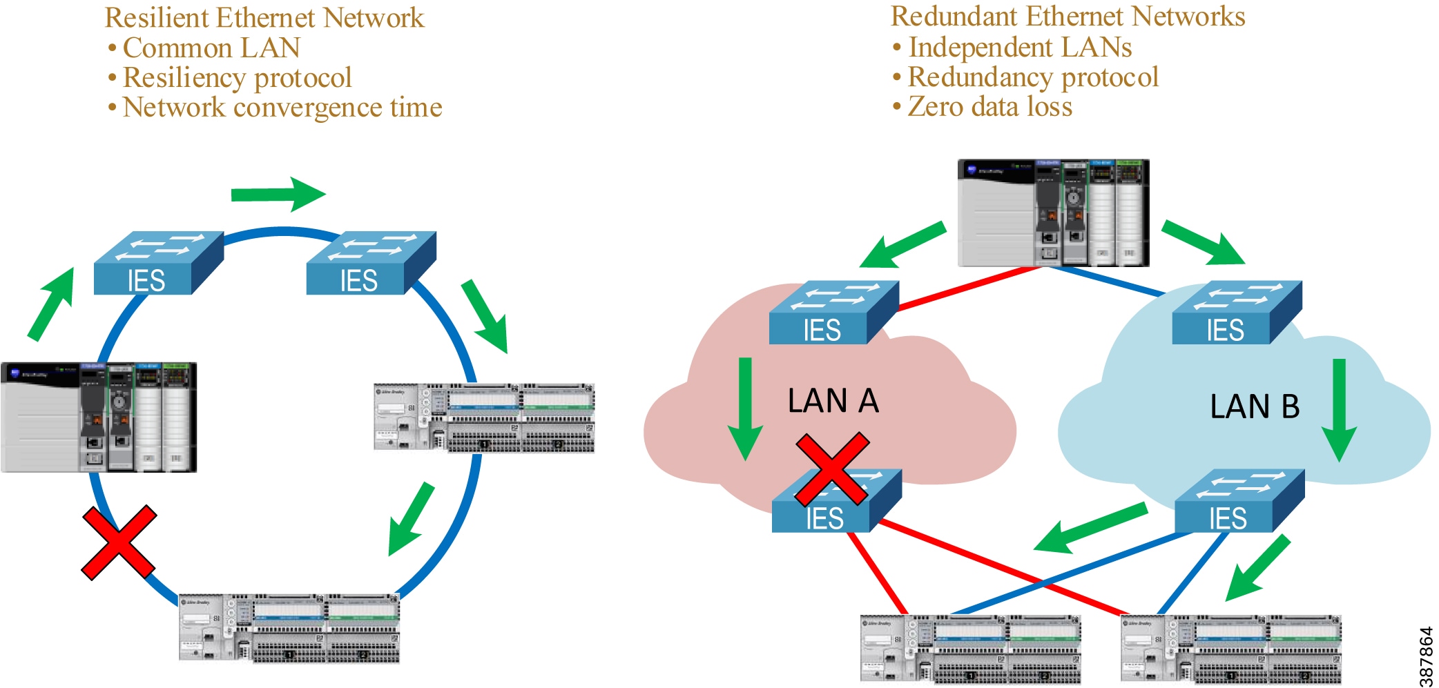
An IACS device with PRP technology (a DAN) has two Ethernet ports that operate in parallel and attach to independent LAN A and LAN B. During normal network operation, a DAN simultaneously sends and receives duplicate Ethernet frames through both ports.
The receiving node accepts whichever frame arrives first and discards the subsequent copy. If a failure occurs in one of the LANs, traffic continues to flow through the other LAN uninterrupted with no convergence time.
Unlike other resiliency protocols, such as Spanning Tree Protocol (STP) or DLR, PRP does not require reconfiguration in LAN A or B after the fault (e.g., unblocking the port). PRP provides redundancy by using duplicate network infrastructure rather than redundant paths in the same network.
Figure 2-1 Redundant Path versus Redundant Networks
DAN Operation
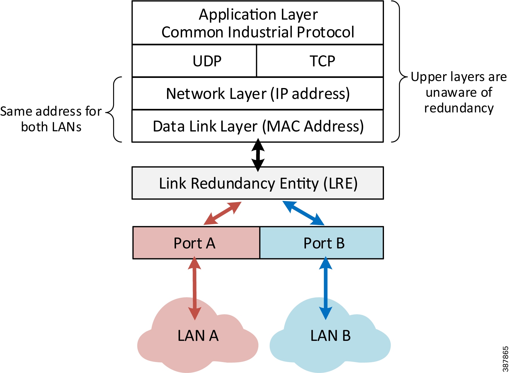
A DAN has two Ethernet ports that are attached to the upper communication layers of the IACS device through the Link Redundancy Entity (LRE). The LRE handles duplication of packets and management of redundancy (Figure 2-2). The upper layers are unaware of redundancy because the LRE provides to them the same interface as a non-redundant network adapter.

Note![]() A DAN uses the same MAC address and IP address to communicate on both LANs.
A DAN uses the same MAC address and IP address to communicate on both LANs.
Figure 2-2 PRP DAN Communication Layers
When a DAN sends a frame to another DAN:
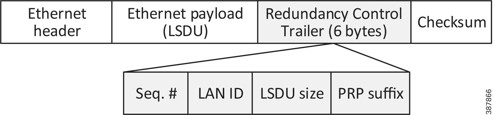
- The LRE creates two copies of the frame and sends them through LAN A and LAN B ports with a Redundancy Check Trailer (RCT) appended to each frame. The 6-byte trailer contains a sequence number, the LAN identifier, frame data size, and the PRP suffix that identifies the trailer type as PRP (Figure 2-3).
- The duplicate frames traverse the two LANs, perhaps under different network conditions and with slightly different delays, and arrive at the destination node.
- The LRE in the destination DAN forwards the first received copy of the frame to the upper layers (without the PRP trailer) and discards the second copy (if it arrives).
- PRP algorithm is designed in a way that it should never reject a legitimate frame, however in rare cases a duplicate frame can be accepted as a new one and passed to the upper layers. This could happen if the duplicate frame arrives with significant time difference. Upper layer protocols (TCP or EtherNet/IP) are able to handle occasional duplicate frames.
Figure 2-3 Ethernet Frame with RCT Appended
Note![]() The RCT trailer adds six bytes to an Ethernet frame. To accommodate a maximum size Ethernet frame (1500 bytes) with the PRP trailer attached, all LAN A and LAN B network devices should be configured with the maximum transmission unit (MTU) size of at least 1506 bytes. This is not required for a RedBox IES.
The RCT trailer adds six bytes to an Ethernet frame. To accommodate a maximum size Ethernet frame (1500 bytes) with the PRP trailer attached, all LAN A and LAN B network devices should be configured with the maximum transmission unit (MTU) size of at least 1506 bytes. This is not required for a RedBox IES.
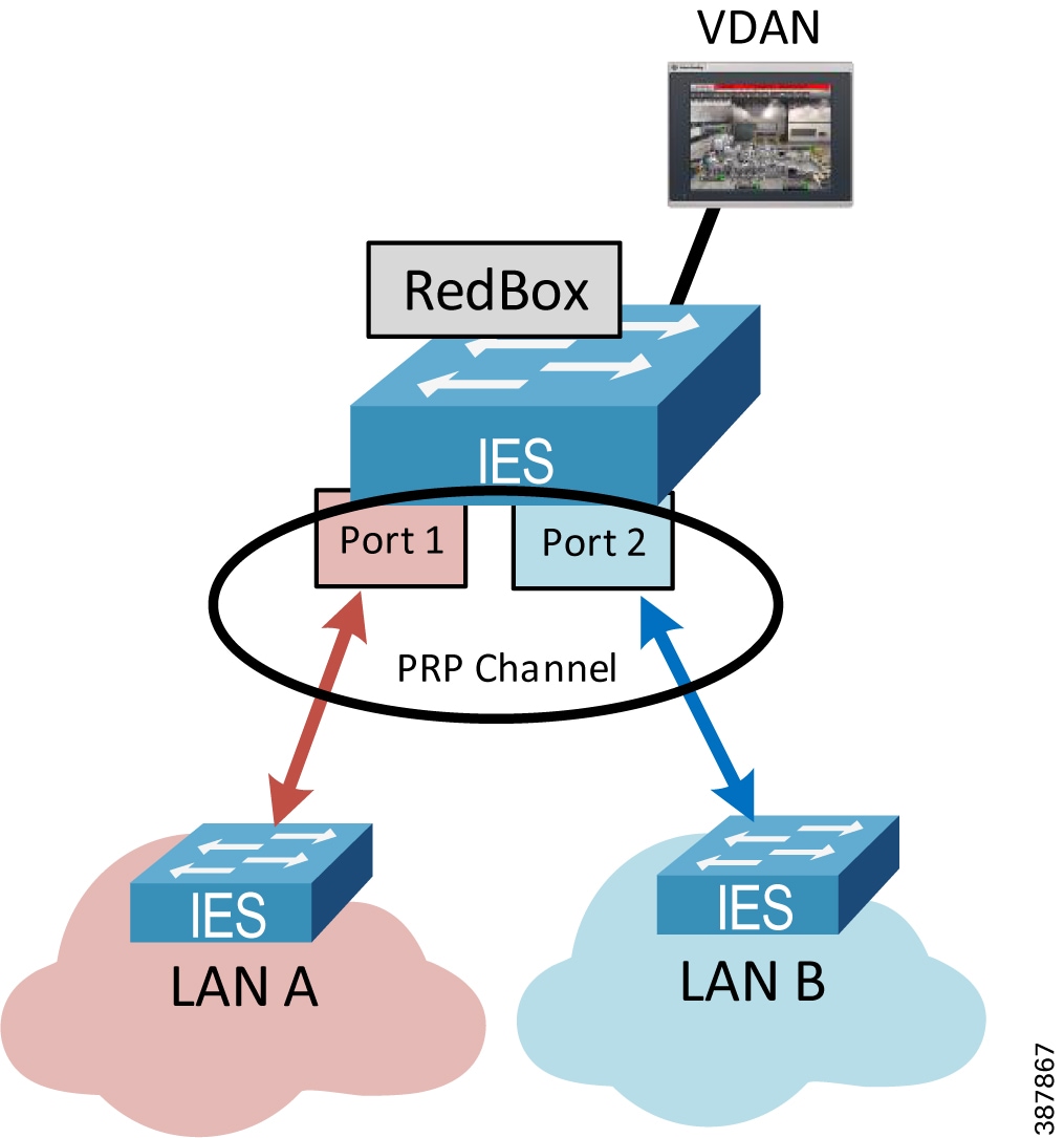
RedBox and VDAN Operation
The RedBox device acts as LRE for one or several connected VDANs or for a non-PRP bridged network segment. The RedBox keeps track of sequence numbers and handles duplicate received frames for multiple VDANs.
Two Gigabit Ethernet ports on the RedBox IES are configured as one logical interface—a PRP channel group (Figure 2-4). The PRP ports can be in access mode for single VLAN deployments, trunk mode to support multiple VLANs, or routed mode. In the channel group, the lower numbered member port is the primary port and connects to LAN A. The higher numbered port is the secondary port and connects to LAN B.
- The Stratix 5400 IES supports one PRP channel. The Stratix 5410 and Stratix 5800 IES support up to two PRP channels.
- Only certain pairs of ports can be used in a PRP channel, depending on the platform.
- A maximum of 512 VDAN entries are supported in the PRP VDAN table. If the VDAN table is full, the switch cannot send supervisory frames for new VDANs.
- The RedBox IES supports a maximum of 512 SAN and DAN entries in the Node table.
- Ports in the PRP channel group cannot be configured for other resiliency protocol, e.g., DLR or Resilient Ethernet Protocol (REP).
- Once the PRP ports are added to the group, individual port settings should not be changed unless the port is removed from the group.
In addition to connecting VDANs, a RedBox IES in the PRP network is necessary in following situations:
- Routing is enabled in the network.
- Connectivity to a non-PRP LAN is required, e.g., a DLR segment, a plant-wide or site-wide connectivity.
- Internet Group Management Protocol (IGMP) querier role is required for multicast management.
- Boundary clock role is required for plant-wide or site-wide time distribution using PTP.
Recommendations for configuring RedBox IES for these use cases are described in later sections of this Design and Implementation Guide.
For more information about Stratix switch PRP functionality and configuration, refer to:
- Stratix Managed Switches User Manual https://literature.rockwellautomation.com/idc/groups/literature/documents/um/1783-um007_-en-p.pdf
- Stratix 5800 Managed Switches User Manual
https://literature.rockwellautomation.com/idc/groups/literature/documents/um/1783-um012_-en-p.pdf
Note![]() A RedBox IES in a PRP system is a single point of failure. IACS availability requirements should be evaluated when connecting critical devices to a RedBox. Best network practices must be implemented, such as using redundant power supplies, installing proper cabling and grounding, and avoiding uncontrolled loops in the LAN A and LAN B topologies.
A RedBox IES in a PRP system is a single point of failure. IACS availability requirements should be evaluated when connecting critical devices to a RedBox. Best network practices must be implemented, such as using redundant power supplies, installing proper cabling and grounding, and avoiding uncontrolled loops in the LAN A and LAN B topologies.
SAN Operation
Devices without PRP support (SAN) can be included in the PRP topology as non-redundant devices connected to either LAN A or LAN B:
- A SAN can accept and process Ethernet frames with the RCT attached. The SAN simply ignores the PRP trailer as the Ethernet padding in the frame.
- To avoid duplication of packets for SANs, the DAN or the RedBox IES keeps track of learned MAC addresses in the PRP node table, identifies the device as attached to only one LAN, then sends the frame to that LAN only without the PRP trailer.
- The SAN traffic from one of the LANs can be received and processed by the destination DAN in a normal way.
Note![]() All SANs must have unique IP addresses across the PRP network. Address Conflict Detection (ACD) mechanisms may fail if duplicate addresses are assigned to SANs in different LANs. To avoid that, use RedBoxes and connect devices as VDANs.
All SANs must have unique IP addresses across the PRP network. Address Conflict Detection (ACD) mechanisms may fail if duplicate addresses are assigned to SANs in different LANs. To avoid that, use RedBoxes and connect devices as VDANs.
Network Management and Supervision
Benefits of network redundancy can only be realized if the network status and performance is monitored. This can be achieved with a Network Monitoring Tool (NMT) using Simple Network Management Protocol (SNMP) and other management protocols, EtherNet/IP diagnostic tools, and diagnostic information available in PRP-capable IACS devices and RedBox IES.
PRP nodes (DAN or RedBox) provide real-time PRP statistics and verify if frames from known DANs or VDANs are received via both PRP ports. For more information, refer to Chapter4, “CPwE Parallel Redundancy Protocol Monitoring and Troubleshooting”
Each DAN periodically sends a PRP supervision frame that announces its presence on the network and allows other nodes to check the health of the PRP network. The RedBox sends supervisory frames on behalf of connected VDANs. The supervisory frames are Layer 2 multicast Ethernet frames sent to a reserved multicast MAC address.
Note![]() An NMT should be connected to the PRP network via a RedBox to access IACS devices and IES in both LANs. While LAN A and LAN B are isolated on the network layer, all managed IES and IACS devices should have different IP addresses within and between each LAN for management purposes.
An NMT should be connected to the PRP network via a RedBox to access IACS devices and IES in both LANs. While LAN A and LAN B are isolated on the network layer, all managed IES and IACS devices should have different IP addresses within and between each LAN for management purposes.
Parallel Redundancy Protocol Network Design Recommendations
PRP technology is implemented in IACS devices, therefore network infrastructure devices (other than the RedBoxes) do not have to be PRP capable. PRP is not dependent on any particular LAN topology and should provide a single fault tolerance with zero data loss even with non-resilient topologies in each LAN such as star, linear, or a single switch.
When designing a PRP network, follow these recommendations:
- If possible, use resilient topologies (redundant star, ring) in each LAN for additional resiliency protection. In this case, an extended outage or maintenance in one of the LANs still should allow the IACS to recover from a subsequent fault in the other LAN (with convergence time depending on the resilient LAN protocol).
- Design the architecture to avoid or minimize architecture-wide faults that impact both LANs such as power failures or damage of both redundant cabling paths. Use redundant power sources and physically isolated cabling conduits for each LAN.
- Help protect the network from uncontrolled Ethernet loops that may cause broadcast or multicast storms. Follow best practices and use recommended topologies for resiliency protocols that may be used in LAN A and LAN B (e.g., Spanning Tree, DLR, REP). Do not disable loop prevention mechanisms on infrastructure IES.
- Use the same or similar topologies for both LANs with comparable network latency and number of hops in normal network conditions. Avoid using different types of connectivity between LAN A and LAN B, for example a high-speed wired network for LAN A and low bandwidth, high-latency wireless technology for LAN B.
- Do not connect IES (other than RedBoxes) to both LAN A and LAN B. Direct links between LAN A and LAN B IES are not allowed.
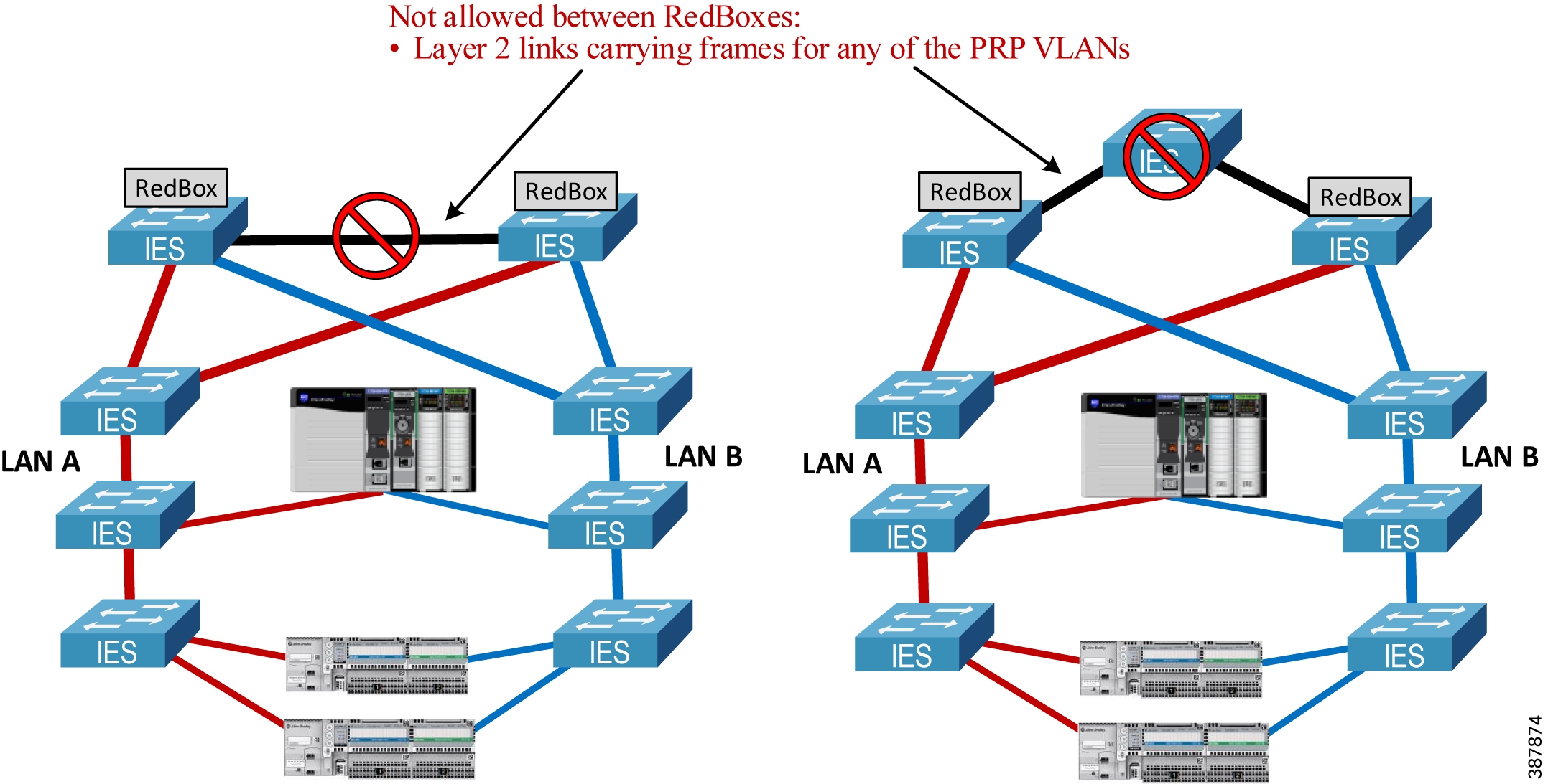
- Do not connect any RedBox IES to each other via a Layer 2 path that bridges any of the VLANs that exist in the PRP network. Such a connection creates a bridging loop in the network. Layer 3 routed paths are allowed.
- If routing is required in the PRP network, configure a RedBox IES as the router. Do not enable routing on the LAN A or LAN B IES. For recommendations on the routing redundancy design with PRP and how to connect to the Industrial Zone network, see Connectivity to the Industrial Zone Network.
- Apply the same recommended network and security practices as for a non-PRP network, such as using managed switches with diagnostic, loop prevention, multicast management and security features, minimizing broadcast domains with VLAN segmentation, hardening the network and the IACS applications against security threats, maintaining good change control practices, and IES configuration management.
Parallel Redundancy Protocol Topology Examples
This section provides some examples of PRP architectures and topologies.
Figure 2-5 shows an example of PRP deployment with two parallel fault-isolated physical paths. This could be useful in mining or transportation applications (e.g., parallel tunnels), marine applications (two sides of a ship), and other similar use cases.
In the example below, both LANs use a ring topology rather than linear topology for additional resiliency. In most greenfield installations, the cost of having a return cable path is insignificant when installing a cable bundle. The benefits of using a resilient LAN topology are greater than the additional effort of configuring and monitoring of a ring protocol.
The example architecture also implements redundant programmable automation controllers (PAC) with ControlLogix ® redundancy for greater availability and protection from controller faults.
Figure 2-5 PRP Topology Example with Parallel Paths
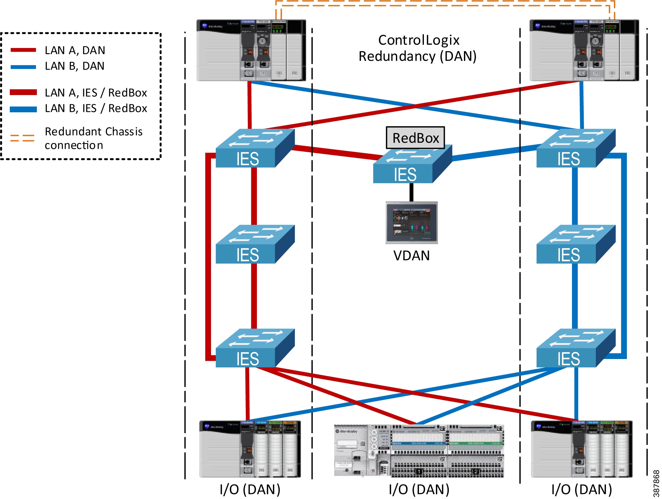
Figure 2-6 shows an example of a PRP topology with dual rings and a single (non-redundant) PAC. A dual-ring topology is common for water/wastewater, mining, oil and gas, and other industries that traditionally have used redundant dual-media topologies over large geographical areas.
Figure 2-6 PRP Topology Example with Dual Rings—Single PAC
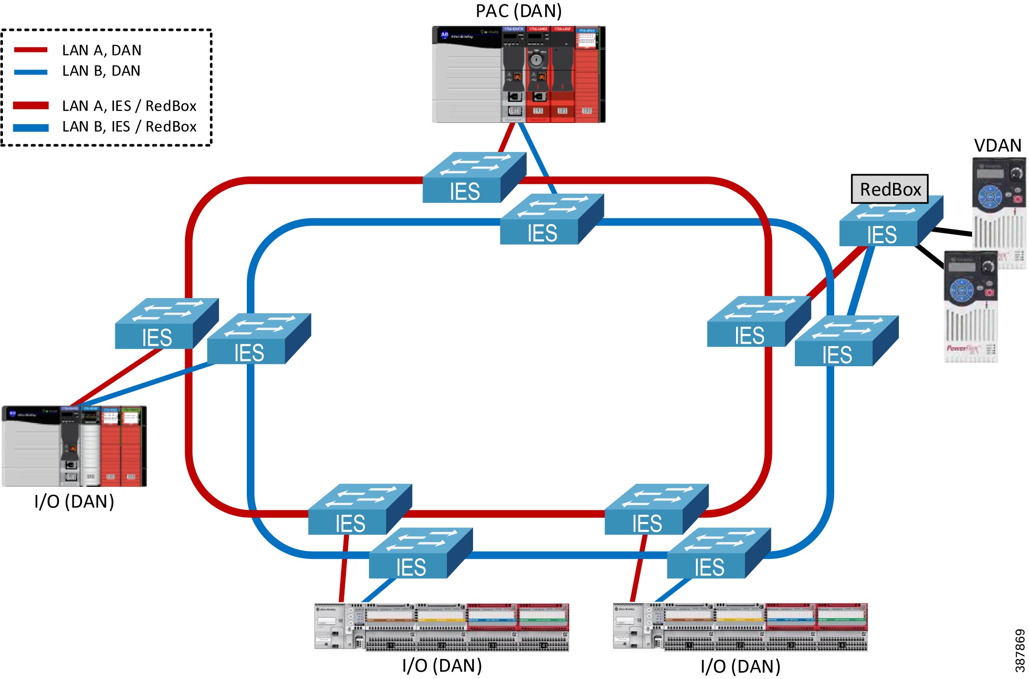
Figure 2-7 shows an example of a PRP topology with dual rings and ControlLogix redundant PACs.
Figure 2-7 PRP Topology Example with Dual Rings—Redundant Controllers
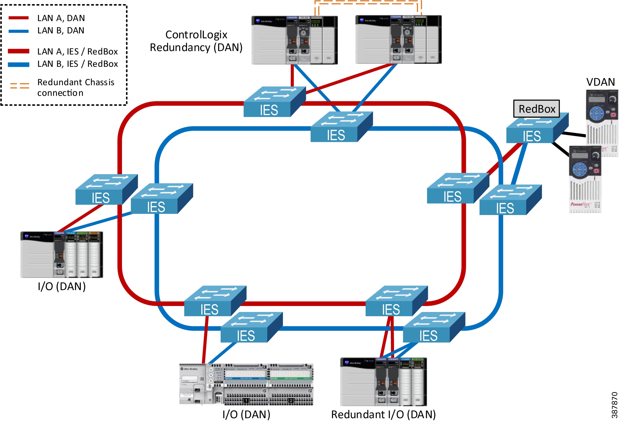
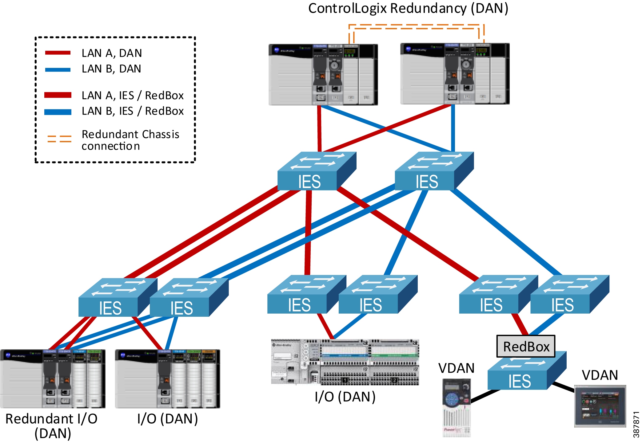
Figure 2-8 shows an example of the star topology in a PRP network.
Note that access IES could also be connected with redundant uplinks to the aggregation IES in the LAN A or B, for example using EtherChannel technology. The cost of additional cabling and available ports should be considered.
Figure 2-8 PRP Star Topology Example
Note![]() The CPwE PRP architecture has been tested and validated using a star, redundant star, and dual ring topology for LAN A and LAN B with a mix of redundant and non-redundant PACs.
The CPwE PRP architecture has been tested and validated using a star, redundant star, and dual ring topology for LAN A and LAN B with a mix of redundant and non-redundant PACs.
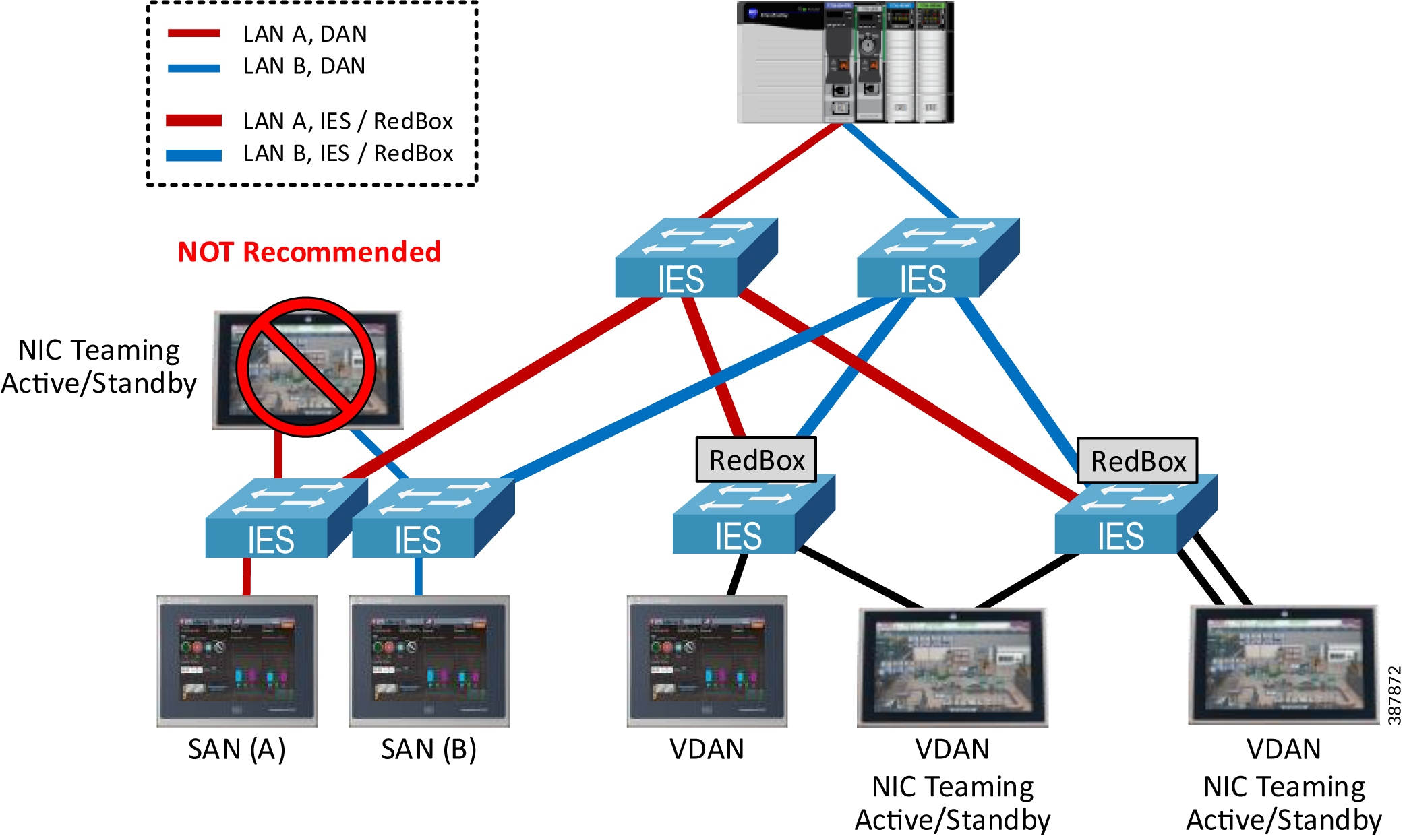
Connecting HMI and PCs to a PRP Network
PCs, HMI terminals and thin clients with a single Ethernet port can be connected to a PRP network:
- As a SAN to a LAN A or LAN B (two terminals with identical content can be connected to each LAN for redundancy)
- As a VDAN to a RedBox
PCs with NIC Teaming or thin clients with redundant Ethernet ports in the Active/Standby mode can be connected as a VDAN to one or two RedBoxes using two Ethernet links. See Figure 2-9 below.
- Do NOT connect devices with redundant NICs without native PRP support to LAN A and LAN B switches. Doing so may cause significant delays for HMI traffic during the switchover between the NICs.
Note![]() Validating third-party network adapters with native PRP support is out of scope for CPwE PRP.
Validating third-party network adapters with native PRP support is out of scope for CPwE PRP.
Figure 2-9 Connecting PC and HMI Terminals
Using Wireless Media with PRP
PRP over wireless can, in principle, be supported when:
- Both LANs use the same wireless technology with similar latency
- Separate wireless channels are used for LAN A and LAN B links
- Radios and other infrastructure equipment either support PRP as a feature or can forward Ethernet frames with PRP trailer without modification
It is highly recommended to validate PRP operation with the selected wireless equipment and verify compatibility with the vendor before deployment.
Note![]() PRP over wireless is out of scope for this release of CPwE PRP architecture.
PRP over wireless is out of scope for this release of CPwE PRP architecture.
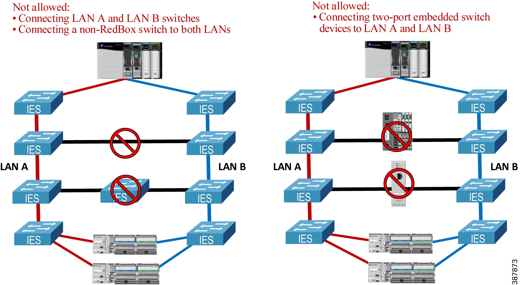
Unsupported Topologies
This section describes a number of invalid PRP topologies or topologies that are not recommended due to performance or availability concerns.
- LAN A and LAN B infrastructure cannot be bridged together using a direct link, a non-RedBox IES, or a 2-port embedded switch device that does not support PRP (e.g., a ControlLogix 1756-EN2TR module or a 1783-ETAP EtherNet/IP DLR tap module). See Figure 2-10 below.
Figure 2-10 Invalid Topology—Bridging LAN A and LAN B
- RedBox IES cannot be connected through non-PRP ports via a Layer 2 path that forwards traffic from any of the PRP VLANs, including IACS data VLANs, management VLAN, or the native VLAN. See Figure 2-11 below.
Figure 2-11 Invalid Topology—Bridging PRP VLAN via RedBox non-PRP Ports
- LAN A and LAN B topologies should not contain 2-port embedded switch devices, including 1783-ETAP modules, in the data path. Embedded switch devices cannot be configured for the larger MTU sizes to accommodate the PRP trailer in the frame. As a result, maximum size Ethernet frames may be dropped. This also applies to any IES without the option to increase the MTU size (Figure 2-12).
Figure 2-12 Unsupported Topology—Traversing 2-port Embedded Switch Devices
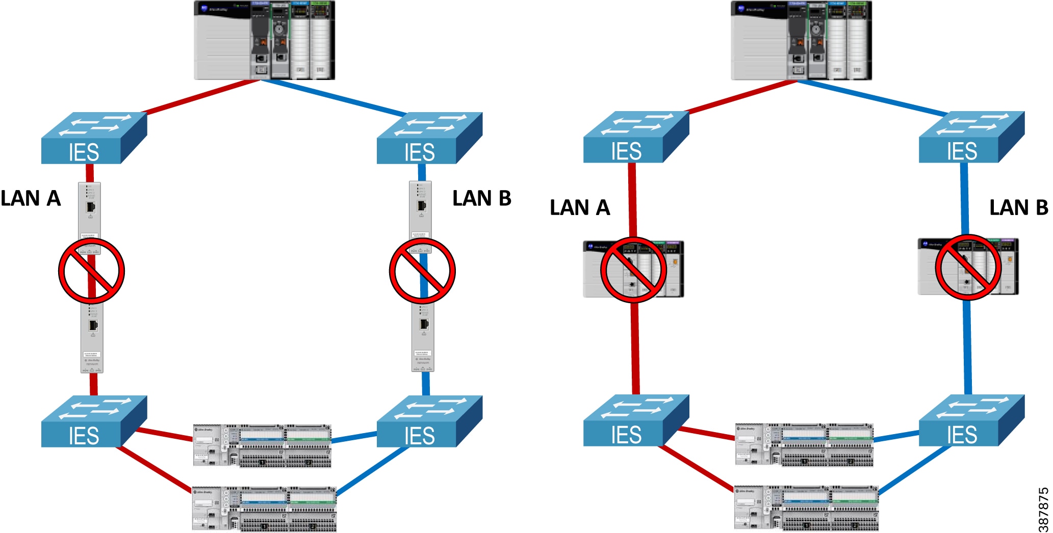
- It is not recommended to combine high-bandwidth low-latency LAN as the primary LAN and low-bandwidth high-latency WAN or wireless technology as the secondary LAN. One of the possible issues could be increased chance of duplicate frames arriving late and being wrongly accepted as non-duplicate (Figure 2-13).
Figure 2-13 Unsupported Topology—Using High-latency Connection as Secondary
Connectivity to the Industrial Zone Network
The CPwE PRP architecture provides guidelines for connecting a PRP-enabled Cell/Area Zone to the plant-wide or site-wide network in the Industrial Zone.
Although IACS applications may exist when a PRP network is deployed as a standalone network (e.g., an isolated I/O network), having plant-wide or site-wide connectivity to the IACS network with PRP technology allows many benefits of the converged network model:
- Remote access for diagnostics and troubleshooting
- Distributed network applications using virtual server environment in the Level 3 Site Operations
- Access to IACS device data and analytics from the Enterprise Zone and / or the cloud as part of the Connected Enterprise® system™.
When connecting a PRP topology with two redundant and isolated LANs to a non-PRP resilient topology, these rules should be followed to avoid bridging loops:
- Only RedBox IES can be used as gateways from a PRP to a non-PRP part of the network.
- Any non-PRP enabled path between RedBox IES should only include Layer 3 (routed) connections.
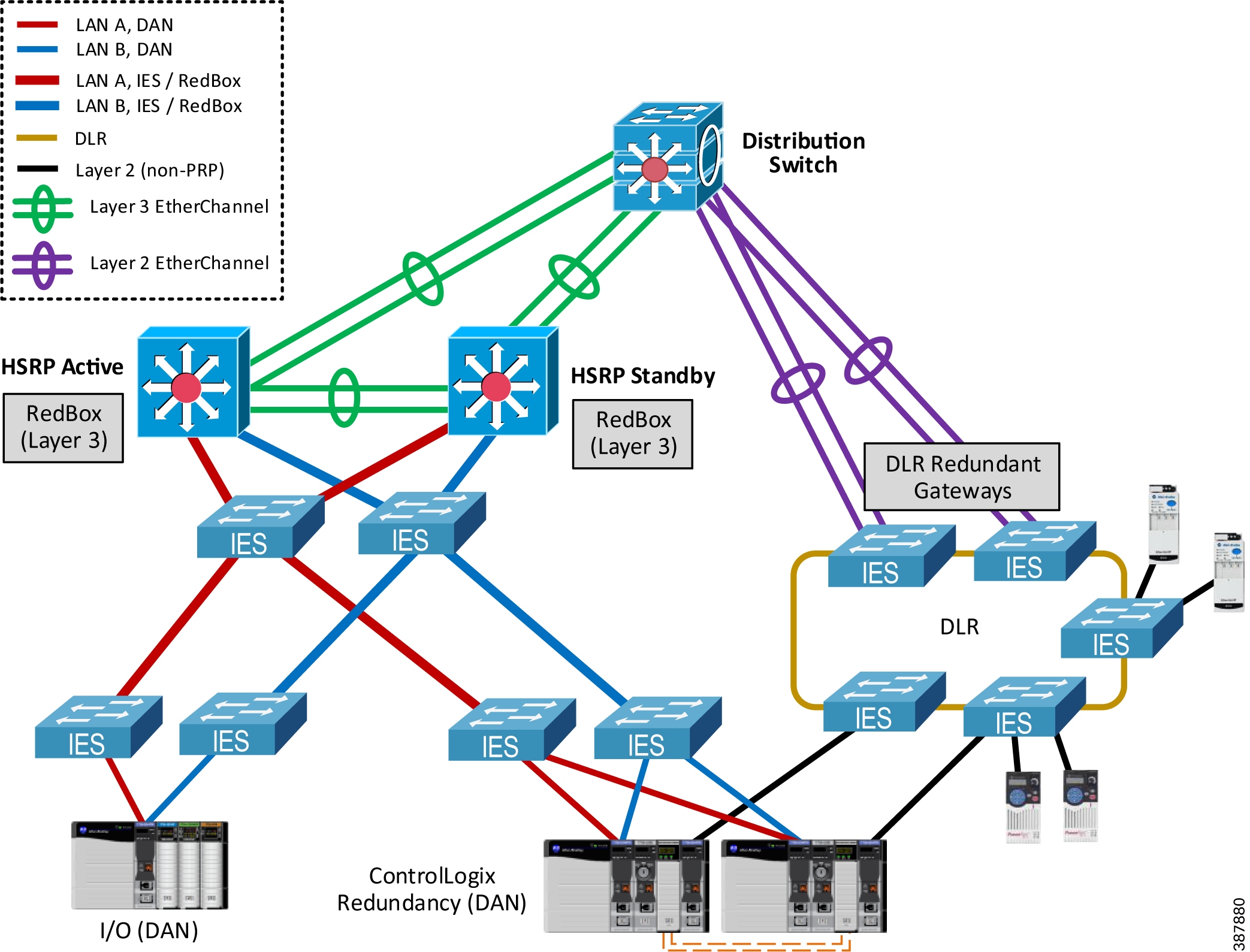
Figure 2-14 shows the CPwE PRP architecture that provides redundant connectivity from a resilient distribution layer in the Industrial Zone to a pair of distribution Layer 3 RedBox IES connected to the PRP Cell/ Area Zone with a star LAN topology.
Figure 2-14 Connectivity to the Industrial Zone
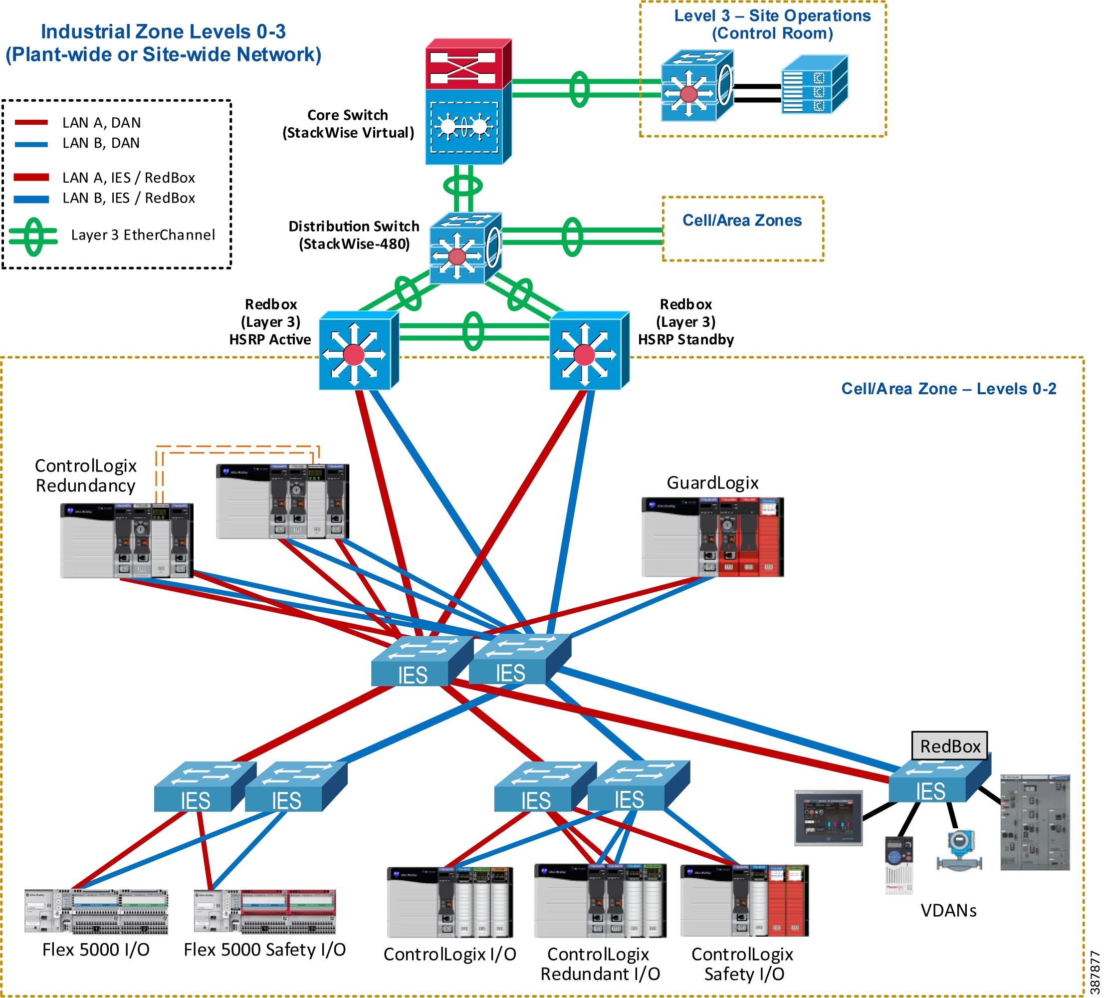
- Redundant Layer 3 RedBox IES are configured with Hot Standby Router Protocol (HSRP) as active/standby default gateways for IP subnets in the PRP topology.
–![]() Layer 3 RedBox IES use PRP channel ports to send HSRP hello packets and monitor redundancy state.
Layer 3 RedBox IES use PRP channel ports to send HSRP hello packets and monitor redundancy state.
- Redundant links between Layer 3 RedBox IES and uplinks to the distribution stack are configured as Layer 3 EtherChannels (routed ports).
- Dynamic routing protocol is configured between the distribution Layer 3 RedBox IES with HSRP pair and the distribution switch stack.
–![]() Enhanced Interior Gateway Routing Protocol (EIGRP) has been validated as part of the CPwE PRP.
Enhanced Interior Gateway Routing Protocol (EIGRP) has been validated as part of the CPwE PRP.
–![]() Open Shortest Path First (OSPF) routing protocol can also be used depending on the existing infrastructure and requirements. CPwE PRP has not been validated with OSPF.
Open Shortest Path First (OSPF) routing protocol can also be used depending on the existing infrastructure and requirements. CPwE PRP has not been validated with OSPF.
–![]() Static routes between RedBox IES and the distribution / core layer are allowed but not recommended due to anincreased complexity of configuration and maintenance in large environments. CPwE PRP has not been validated with static routing.
Static routes between RedBox IES and the distribution / core layer are allowed but not recommended due to anincreased complexity of configuration and maintenance in large environments. CPwE PRP has not been validated with static routing.
–![]() Other resiliency protocols and technologies can be used as outlined in the CPwE Resiliency DIG but have not been tested and validated as part of this CPwE PRP.
Other resiliency protocols and technologies can be used as outlined in the CPwE Resiliency DIG but have not been tested and validated as part of this CPwE PRP.
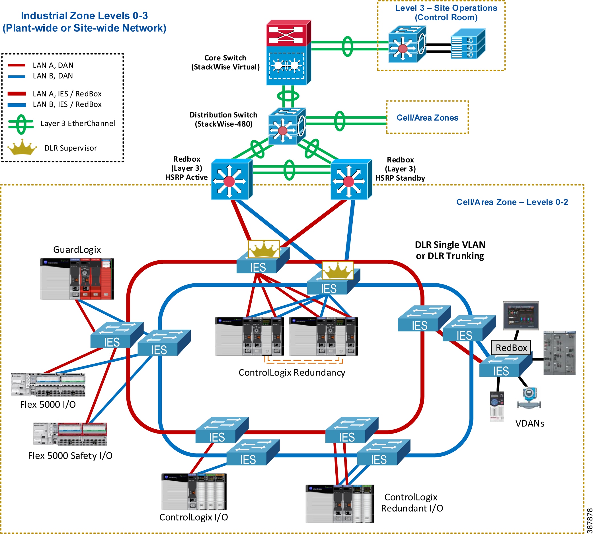
Figure 2-15 shows a similar CPwE PRP architecture with redundant connectivity via a pair of Layer 3 RedBox IES where DLR is used in the PRP Cell/Area Zone as a ring LAN topology.
Figure 2-15 Connectivity to the Industrial Zone (DLR LAN Topology)
EtherChannel, HSRP, and Routing Protocol Considerations
General EtherChannel and HSRP recommendations and configuration guidelines are provided in the CPwE Resiliency Design and Implementation Guide:
- Deploying a Resilient Converged Plantwide Ethernet Architecture
https://literature.rockwellautomation.com/idc/groups/literature/documents/td/enet-td010_-en-p.pdf
For information about EIGRP design and configuration, refer to:
- Enhanced Interior Gateway Routing Protocol
http://www.cisco.com/c/en/us/support/docs/ip/enhanced-interior-gateway-routing-protocol-eigrp/16406-eigrp-toc.html
For information about OSPF, refer to:
- OSPF Design Guide
http://www.cisco.com/c/en/us/support/docs/ip/open-shortest-path-first-ospf/7039-1.html
Note![]() HSRP and EIGRP features require Layer 3 firmware level for Stratix IES and Network Advantage license type for Cisco Catalyst 9300 switches.
HSRP and EIGRP features require Layer 3 firmware level for Stratix IES and Network Advantage license type for Cisco Catalyst 9300 switches.
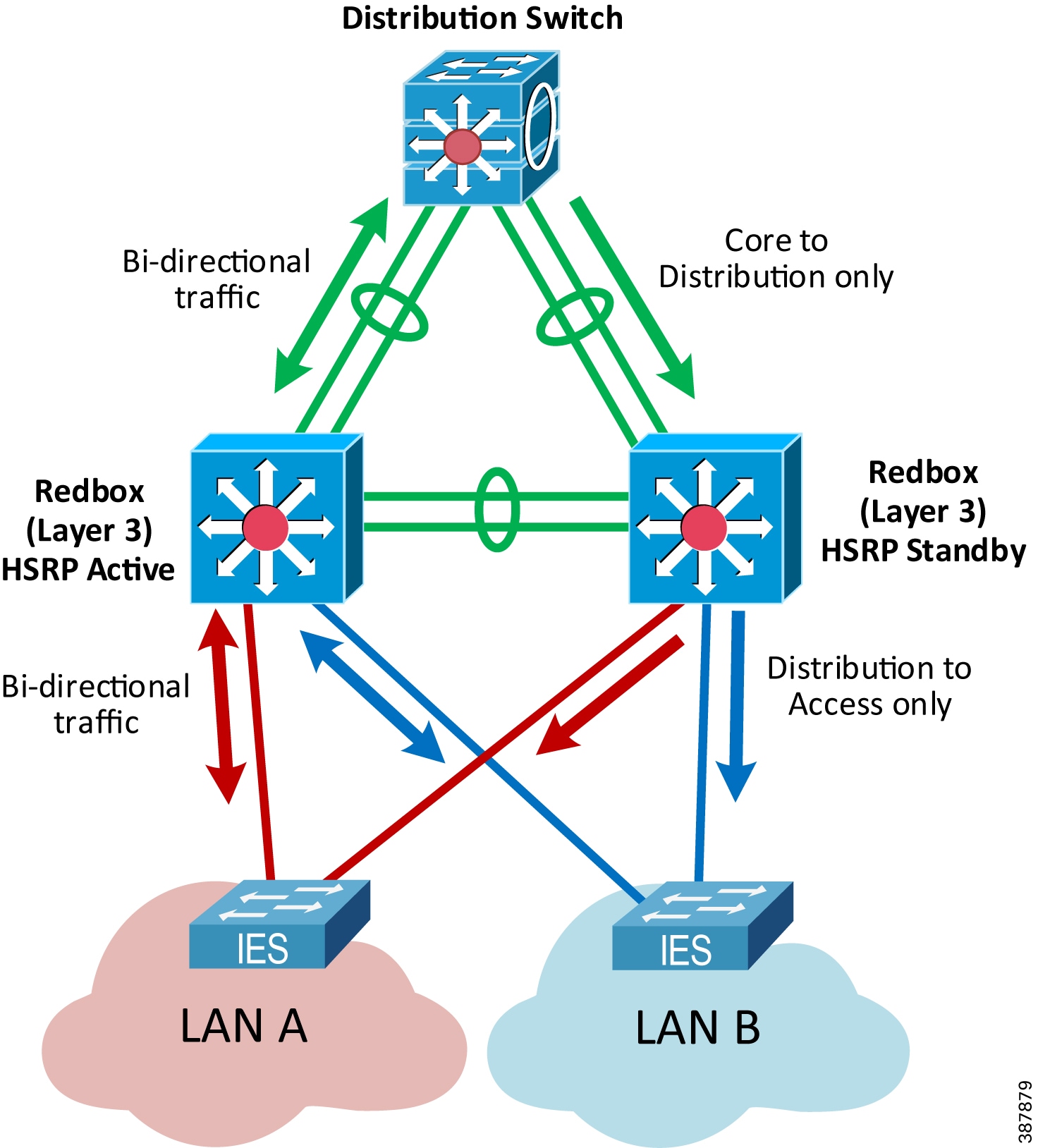
An important consideration for the CPwE PRP routed design is that both Layer 3 RedBox IES carry traffic from the Industrial Zone core network to the Cell/Area Zone, e.g., from an HMI server to an HMI client or a controller (Figure 2-16).
This is due to the equal cost routing in EIGRP or OSPF on the distribution switch where downstream traffic is split roughly evenly between the links to the RedBoxes. As a result, a failure of either the active or the standby HSRP RedBox IES may impact the IACS traffic from Level 3 Site Operation. Similarly, restoring a RedBox IES as the standby HSRP gateway may lead to comparatively small convergence times as the traffic is restored on the second path.
Figure 2-16 Routed Traffic with PRP
The recommended and validated EtherChannel, HSRP, and EIGRP configuration for CPwE PRP is provided in Chapter3, “CPwE Parallel Redundancy Protocol Configuration”
Routed Traffic Convergence
PRP provides zero-loss redundancy and single-fault tolerance for Layer 2 (Ethernet) traffic in the PRP network, including protection against a LAN switch fault or a link fault affecting a DAN, a LAN switch or a PRP channel port on a RedBox.
Layer 3 (routed) traffic traverses a Layer 3 switch (the default gateway) which must be a RedBox IES. CPwE PRP architecture includes two redundant Layer 3 RedBox IES to provide resiliency for the routed traffic.
Note![]() PRP does not provide zero-loss redundancy for routed traffic when a Layer 3 RedBox fails. Routed traffic is interrupted and reconverges during faults impacting the Layer 3 RedBox IES or routed uplinks connected to the RedBoxes.
PRP does not provide zero-loss redundancy for routed traffic when a Layer 3 RedBox fails. Routed traffic is interrupted and reconverges during faults impacting the Layer 3 RedBox IES or routed uplinks connected to the RedBoxes.
Depending on the fault type, convergence time for routed IACS data may include:
- HSRP failover time between Layer 3 RedBox IES
- Dynamic routing protocol convergence
- EtherChannel failover
- Layer 2 switched network convergence (e.g., MAC table updates)
Different routing configurations, protocols and distribution switch platforms may provide different results. Table 2-2 summarizes various faults and the observed impact on the routed traffic in the CPwE PRP testing.
|
1.With HSRP hold timers 750 ms, EIGRP routing protocol and LACP Active EtherChannel mode. |
Note![]() It is important to evaluate IACS application requirements for the routed traffic and compare with the expected convergence times. For example, timeout period with typical Requested Packet Interval (RPI) values for routed CIP Class 1 data (Produced/Consumed tags) may be lower than the HSRP convergence. As a result, Produced/Consumed connections may be dropped during a Layer 3 RedBox failure.
It is important to evaluate IACS application requirements for the routed traffic and compare with the expected convergence times. For example, timeout period with typical Requested Packet Interval (RPI) values for routed CIP Class 1 data (Produced/Consumed tags) may be lower than the HSRP convergence. As a result, Produced/Consumed connections may be dropped during a Layer 3 RedBox failure.
Connectivity to Device Level Ring
The ODVA, Inc. Device Level Ring (DLR) resilient LAN technology is designed to provide ring topology resiliency for critical IACS applications. DLR supports fast ring convergence (single-fault tolerant) in the event of an IACS device or link failure.
For more information on DLR in CPwE, refer to:
- Deploying Device Level Ring within a Converged Plantwide Ethernet Architecture
https://literature.rockwellautomation.com/idc/groups/literature/documents/td/enet-td015_-en-p.pdf
This section describes recommendations for connecting an existing DLR topology without PRP to a PRP architecture.
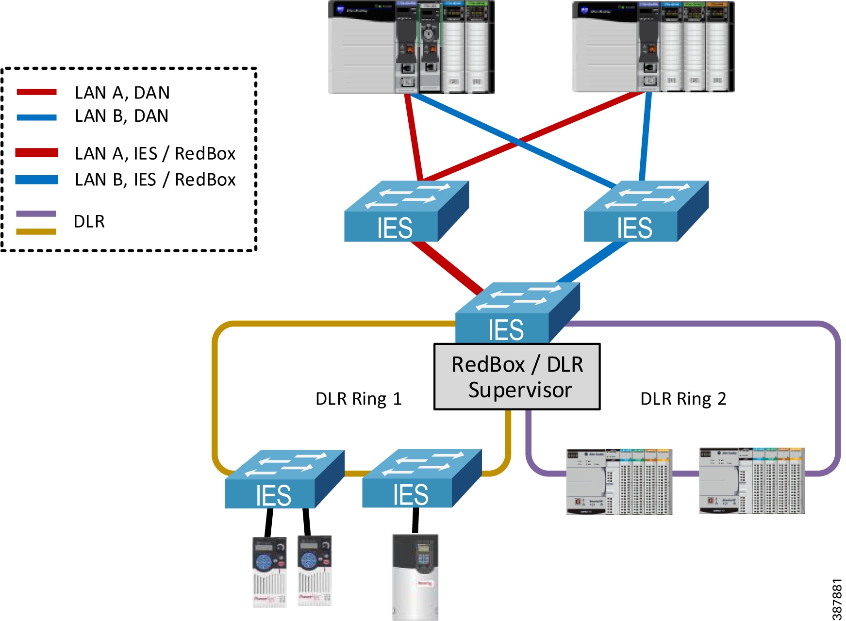
- The recommended resilient architecture is to connect the DLR topology via a separate distribution switch (Figure 2-17) below.
–![]() A controller chassis can be connected to both PRP and DLR networks using separate Ether-Net/IP modules in the chassis. In this example, a ControlLogix Redundancy chassis is con-nected to the PRP topology and the switch DLR topology.
A controller chassis can be connected to both PRP and DLR networks using separate Ether-Net/IP modules in the chassis. In this example, a ControlLogix Redundancy chassis is con-nected to the PRP topology and the switch DLR topology.
Figure 2-17 Connecting Controller Chassis to both PRP and DLR
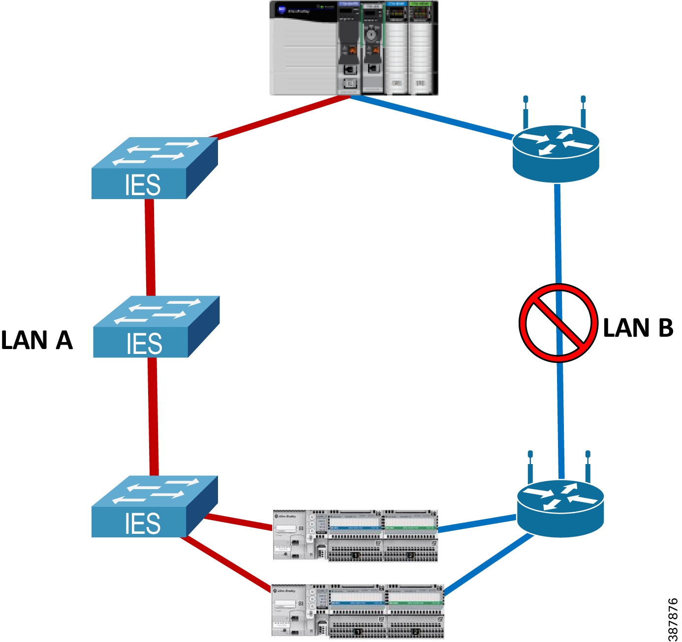
- An alternative non-redundant option is to use a RedBox IES as the DLR supervisor for one or multiple rings (Figure 2-18) below. DLR ports cannot be the same as the PRP channel ports.
Note![]() In this case the RedBox is a single point of failure for the traffic between the DLR and the PRP topologies. This architecture is not recommended for critical IACS data traversing the RedBox and has not been validated for performance or scalability in this CPwE PRP.
In this case the RedBox is a single point of failure for the traffic between the DLR and the PRP topologies. This architecture is not recommended for critical IACS data traversing the RedBox and has not been validated for performance or scalability in this CPwE PRP.
Figure 2-18 PRP to DLR Connectivity via a Single RedBox
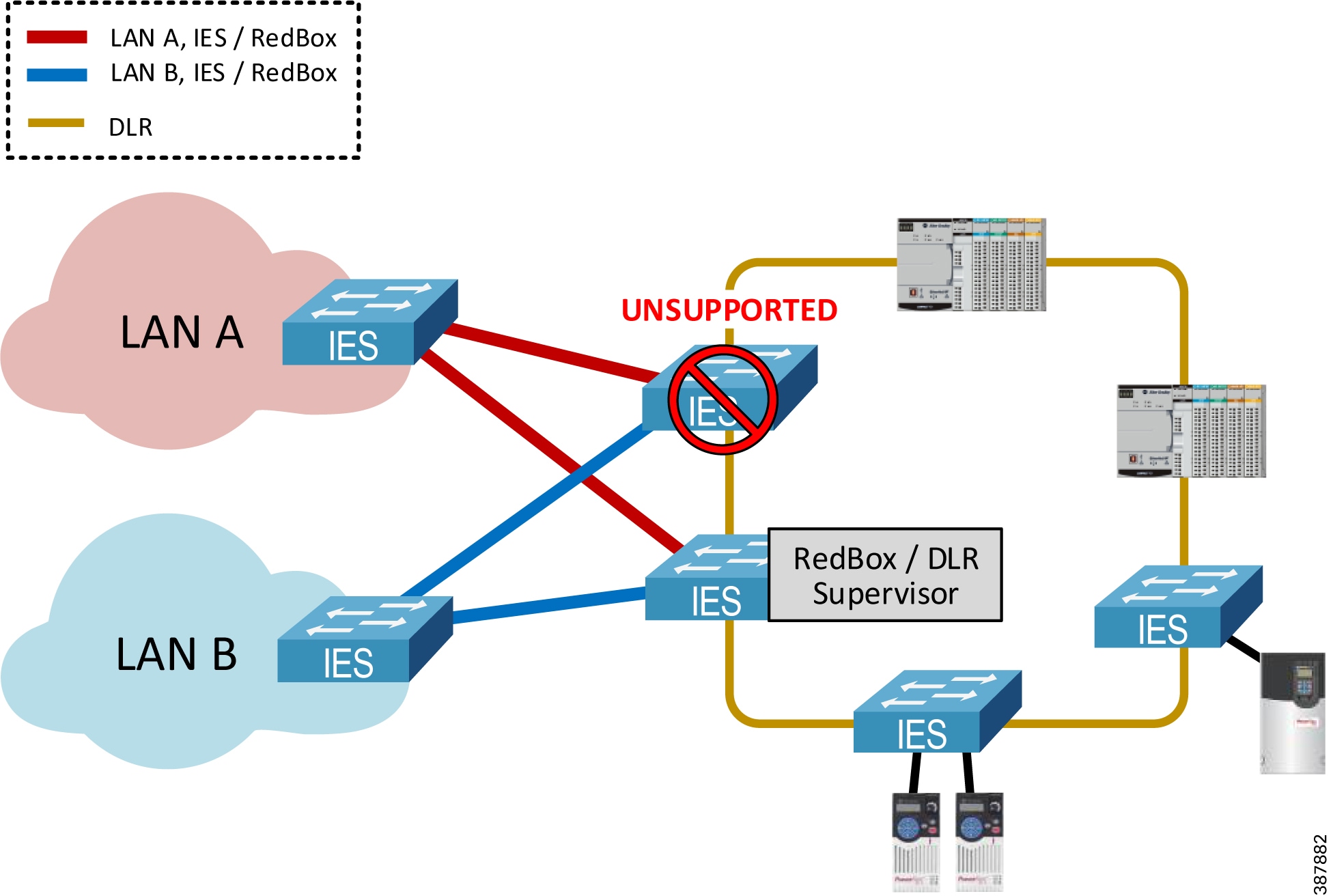
- Using two RedBox IES as redundant DLR gateways is not supported due to increased convergence time for traffic traversing the gateways during certain faults, which exceeded requirements for IACS applications (Figure 2-19) below.
Figure 2-19 Unsupported Topology—PRP to DLR Redundant Gateways
Note![]() An EtherNet/IP module in the PRP mode cannot be used as part of the DLR or a linear topology. PRP-enabled modules do not implement the embedded switch technology and traffic cannot traverse from port A to port B. Similarly, an Ethernet module in the DLR mode cannot be connected to both LAN A and LAN B.
An EtherNet/IP module in the PRP mode cannot be used as part of the DLR or a linear topology. PRP-enabled modules do not implement the embedded switch technology and traffic cannot traverse from port A to port B. Similarly, an Ethernet module in the DLR mode cannot be connected to both LAN A and LAN B.
Network Services Recommendations
This section provides recommendations for network services and IES features that could be required in the PRP-enabled IACS network, such as VLAN segmentation and trunking, multicast traffic management, time synchronization, and Network Address Translation (NAT).
VLAN Segmentation and Trunking
PRP technology can be deployed in networks with VLAN segmentation. Links between IES can be configured with VLAN trunking to carry traffic from DANs and VDANs that belong to multiple VLANs (Figure 2-20) below.
Figure 2-20 VLAN Segmentation (Zoning) in PRP Network
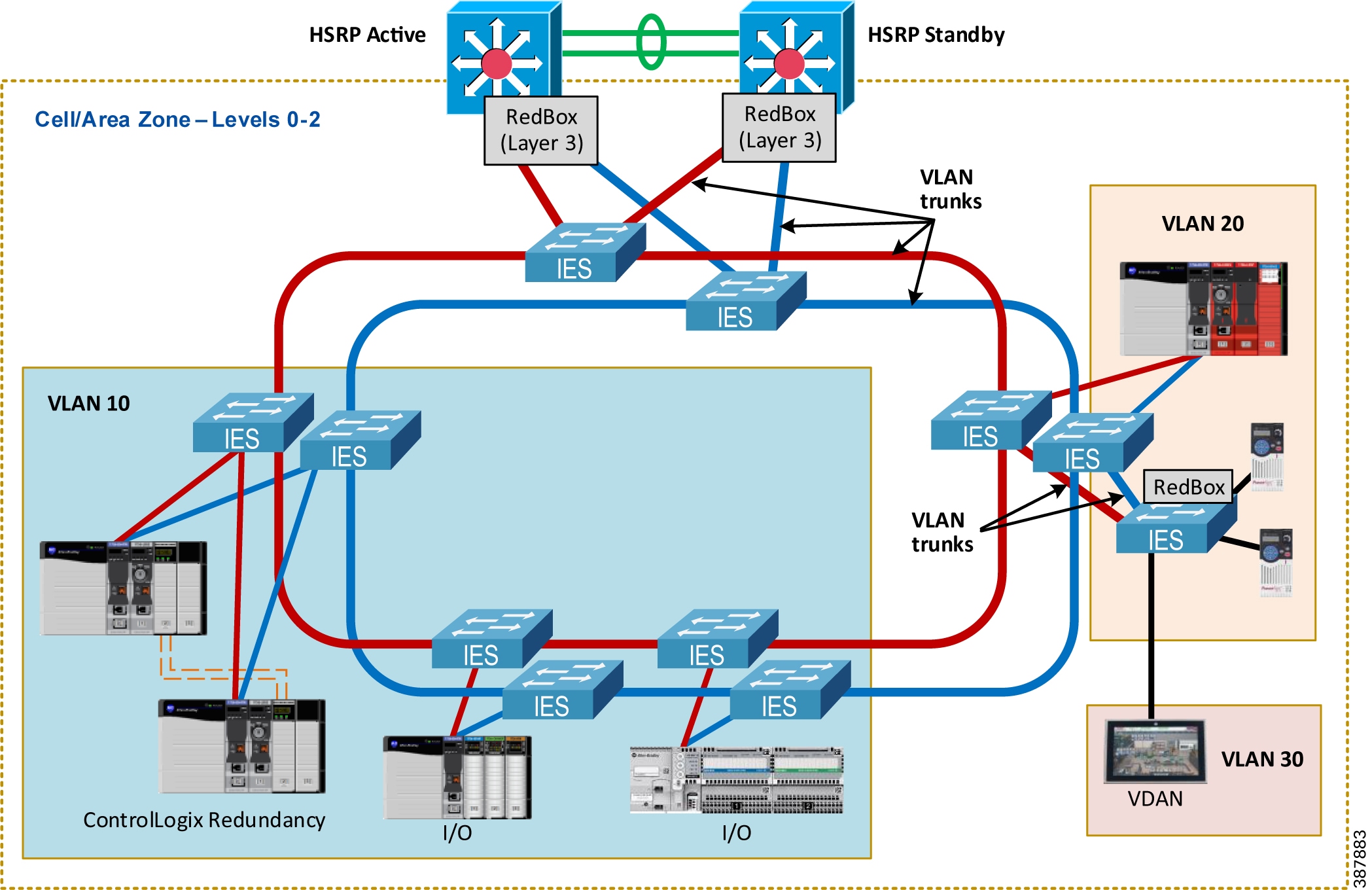
Follow these recommendations when using VLAN segmentation with PRP:
- Both PRP ports on a DAN should be connected to the same VLAN in LAN A and LAN B.
- The PRP channel ports on a RedBox IES can be configured as VLAN trunk ports (more common) or access mode ports (i.e., single VLAN). Trunk mode allows having VDANs in multiple VLANs or using a separate management VLAN for the RedBox IES.
- PRP channels on the redundant Layer 3 RedBox IES in CPwE PRP should be configured as VLAN trunks. The architecture has been validated with inter-VLAN IACS traffic which is routed through the Layer 3 RedBox with HSRP.
–![]() Traffic between VLANs (Layer 3) is impacted if the active HSRP gateway fails. Convergence time depends on the HSRP parameters.
Traffic between VLANs (Layer 3) is impacted if the active HSRP gateway fails. Convergence time depends on the HSRP parameters.
- Links between IES in each PRP LAN should be configured as VLAN trunks. Per CPwE best practice, the native VLAN should be different from any of the IACS VLANs
Note![]() PRP supervisory frames are Layer 2 multicast Ethernet frames that cannot be routed between VLANs. As a result, DANs can only report diagnostic information about PRP devices in their VLANs.
PRP supervisory frames are Layer 2 multicast Ethernet frames that cannot be routed between VLANs. As a result, DANs can only report diagnostic information about PRP devices in their VLANs.
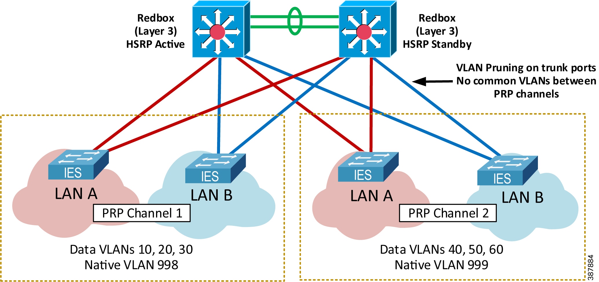
For network architectures with two PRP channels configured on the same pair of Layer 3 RedBox IES, configure VLANs as follows to avoid network loops (Figure 2-21) below.
- Use separate sets of data, management and native VLANs in Cell/Area Zones connected to each PRP channels
- Configure the allowed VLAN list on the trunk ports in the PRP channel group (VLAN pruning), making sure that VLANs from the other PRP channel are not allowed.
Figure 2-21 Two PRP Channels with VLAN Pruning
Spanning Tree Protocol
Design and configuration of the Spanning Tree Protocol (STP) in PRP LAN A and LAN B should follow general recommendations in the CPwE Resiliency Design and Implementation Guide. Special considerations exist for STP operation between a RedBox IES and infrastructure IES (Figure 2-22) below.
- A RedBox IES serves as a boundary between separate STP instances in LAN A and LAN B. There should be no common STP domain bridging two redundant LAN A and LAN B.
- Bridge Protocol Data Unit (BPDU) frames from STP are filtered on the PRP channel ports. As a result, LAN A and LAN B switches exclude the RedBox IES in the STP operation.
- STP is running on the RedBox IES by default and should be kept enabled for loop prevention on the non-PRP ports.
–![]() Two RedBox IES cannot be connected to each other via non-PRP ports. Doing so will cause a bridging loop.
Two RedBox IES cannot be connected to each other via non-PRP ports. Doing so will cause a bridging loop.
- PortFast Trunk mode should be configured for the PRP channel group on all RedBox IES, including redundant Layer 3 RedBox IES, and on the LAN A and LAN B IES ports connected to the RedBox. This is necessary to minimize port recovery time during network faults.
- Best practices for STP should be followed within each LAN, such as explicitly configuring the primary and secondary STP root bridge, using recommended redundant star topologies, and avoiding complex meshed topologies.
Figure 2-22 Spanning Tree Operation in the PRP Network

Note![]() Other resiliency protocols such as DLR and REP, if present in the PRP LAN topologies, may have their own considerations for STP interoperability, separate from the PRP considerations. Refer to the corresponding CPwE DLR Design Guide and CPwE Resiliency Design and Implementation Guide for more information.
Other resiliency protocols such as DLR and REP, if present in the PRP LAN topologies, may have their own considerations for STP interoperability, separate from the PRP considerations. Refer to the corresponding CPwE DLR Design Guide and CPwE Resiliency Design and Implementation Guide for more information.
Multicast Management
Multicast EtherNet/IP traffic is required for I/O and consumed data in ControlLogix Redundancy and for CIP Sync communication using Precision Time Protocol (PTP). Both types of multicast data could be used in IACS applications where PRP technology is deployed.
It is critical to follow design and configuration guidelines for multicast traffic management in CPwE PRP to make sure that high availability is achieved:
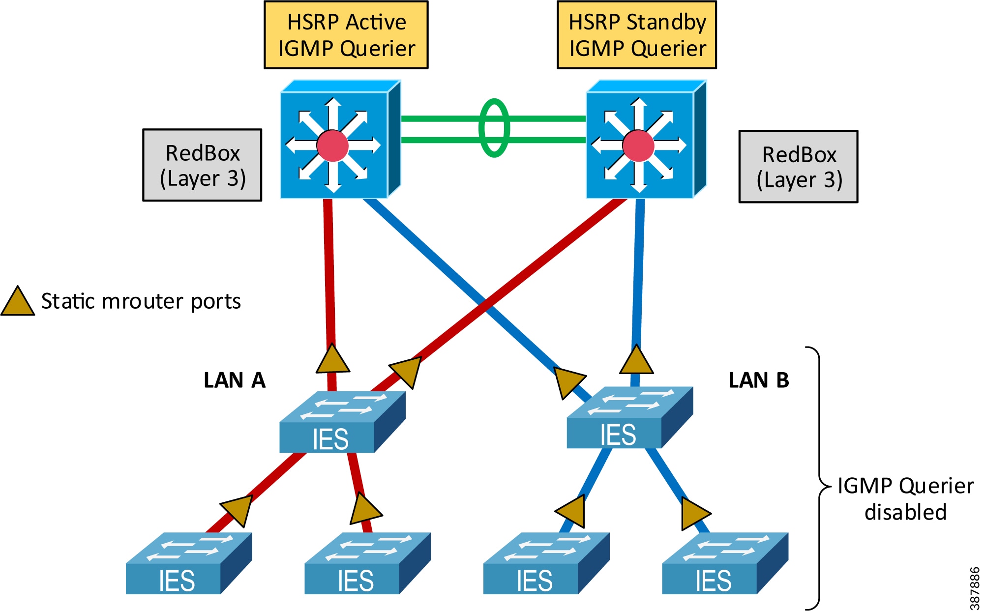
- Enable Internet Group Management Protocol (IGMP) snooping on all IES to reduce the amount of unnecessary multicast traffic to end nodes. IGMP snooping is enabled by default after Express Setup on Stratix managed switches.
- Configure IGMP querier on the redundant Layer 3 RedBox IES with HSRP. Make sure that at least two IGMP queriers are present.
–![]() In order to win the querier election, switches should have the lowest IP addresses in the subnet.
In order to win the querier election, switches should have the lowest IP addresses in the subnet.
–![]() For networks without routing (not common), a Layer 2 RedBox can be used as a querier
For networks without routing (not common), a Layer 2 RedBox can be used as a querier
- Disable IGMP querier on each IES in LAN A and LAN B.
- Configure uplink ports on the LAN IES as static multicast router (mrouter) ports, specifically the ports that could be in the path to the IGMP querier (distribution RedBox IES). This configuration enables multicast traffic flow in the topology when the IGMP querier changes (for example when the active HSRP gateway reboots).
Figure 2-23 below illustrates IGMP snooping configuration in the PRP topology. For details on how to configure these settings, refer to Chapter3, “CPwE Parallel Redundancy Protocol Configuration”
Figure 2-23 Multicast Management with PRP
Note![]() After a LAN in a PRP network encounters a fault and is then repaired, there could be a delay until the IGMP querier reinstates the multicast traffic in the recovered LAN (typically within 2 minutes after the LAN is repaired). During that time, the other LAN will continue forwarding multicast traffic, however, PRP redundancy is not provided for multicast data for a short period of time.
After a LAN in a PRP network encounters a fault and is then repaired, there could be a delay until the IGMP querier reinstates the multicast traffic in the recovered LAN (typically within 2 minutes after the LAN is repaired). During that time, the other LAN will continue forwarding multicast traffic, however, PRP redundancy is not provided for multicast data for a short period of time.
Network Address Translation
Network Address Translation (NAT) feature in IES provides benefits to OEM machine or process skid builders, such as IP address reuse and commissioning of “cookie cutter” machines without reprogramming, easier maintenance of machine configurations and controller programs, and better traffic control and additional security by limiting access only to selected devices on a machine or skid. It may also help plant or site engineers with integrating legacy stand-alone equipment into the plant-wide or site-wide network.
PRP technology is compatible with NAT since PRP operates in Layer 2 and is transparent to the higher layers of the network stack where IP addresses are used.
There are two possible implementations of NAT in a PRP topology (Figure 2-24) below:
–![]() NAT configurations must match exactly between switches
NAT configurations must match exactly between switches
Figure 2-24 Network Address Translation with PRP
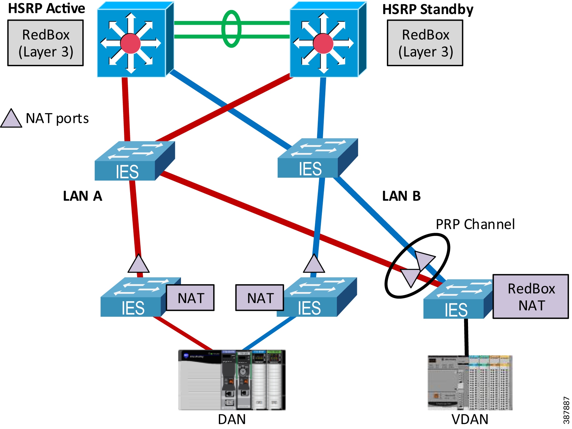
Since CPwE PRP implements HSRP for router (default gateway) redundancy, the following translation rules need to be added to the NAT configuration:
- Gateway translation for the virtual IP address of the HSRP gateways
- Public-to-Private translation for the physical IP addresses of both active and standby HSRP gateways (RedBox IES)
Other general NAT recommendations and limitations may apply, for example topology considerations, multicast restrictions, or application restrictions. For more information on NAT with Stratix IES, refer to:
- Deploying Network Address Translation (NAT) within a CPwE Architecture
https://literature.rockwellautomation.com/idc/groups/literature/documents/td/enet-td007_-en-p.pdf - Stratix Managed Switches User Manual
https://literature.rockwellautomation.com/idc/groups/literature/documents/um/1783-um007_-en-p.pdf - Stratix 5800 Managed Switches User Manual
https://literature.rockwellautomation.com/idc/groups/literature/documents/um/1783-um012_-en-p.pdf
Dynamic Host Configuration Protocol
Dynamic Host Configuration Protocol (DHCP) assigns IP address information from a pool of available addresses to newly connected devices (DHCP clients) in the network. In industrial networks that use DHCP, managed IES are typically configured with DHCP persistence to assign IP addresses to IACS devices based on a specific port.
DHCP is supported in the PRP topology, including DHCP Persistence.
- DHCP Persistence can be configured on the Layer 2 RedBox IES to automatically assign IP addresses to VDANs based on the port.
- DHCP Persistence can be enabled on the infrastructure IES to assign IP addresses to DANs based on the port, as long as:
–![]() DHCP configuration on LAN A and LAN B switches matches exactly including the DHCP pool range and the reserved addresses per port
DHCP configuration on LAN A and LAN B switches matches exactly including the DHCP pool range and the reserved addresses per port
–![]() A DAN is connected to the same port number on each LAN IES.
A DAN is connected to the same port number on each LAN IES.
–![]() Reserved Only setting is enabled for the DHCP scope.
Reserved Only setting is enabled for the DHCP scope.
- DHCP configuration on the infrastructure IES without DHCP Persistence is not supported. The risk exists of assigning duplicate IP addresses for DANs.
- Using DHCP for SANs is not recommended. If such configuration is required, DHCP scopes in each LAN should not overlap.
- DHCP Snooping should be enabled for the DHCP scope configured on the infrastructure and RedBox IES
Time Distribution in CPwE PRP
This section provides recommendations for plant-wide or site-wide time distribution in the CPwE PRP architecture.
IACS devices use ODVA, Inc. CIP Sync technology based on the IEEE 1588™ Precision Time Protocol (PTP) to synchronize clocks in the control system. CIP Sync is designed for local and plant-wide or site-wide IACS applications requiring very high accuracies.
Industrial computers, application servers, managed IES and other network devices use Network Time Protocol (NTP) for timestamping Factory Talk® Alarms and Events.
For more information on CIP Sync, refer to: https://www.odva.org/technology-standards/distinct-cip-services/cip-sync
For general information on designing and configuring time distribution using CIP Sync (PTP) and NTP in the plant-wide or site-wide network, refer to:
- Deploying Scalable Time Distribution within a Converged Plantwide Ethernet Architecture https://literature.rockwellautomation.com/idc/groups/literature/documents/td/enet-td016_-en-p.pdf
Precision Time Protocol (CIP Sync) with PRP
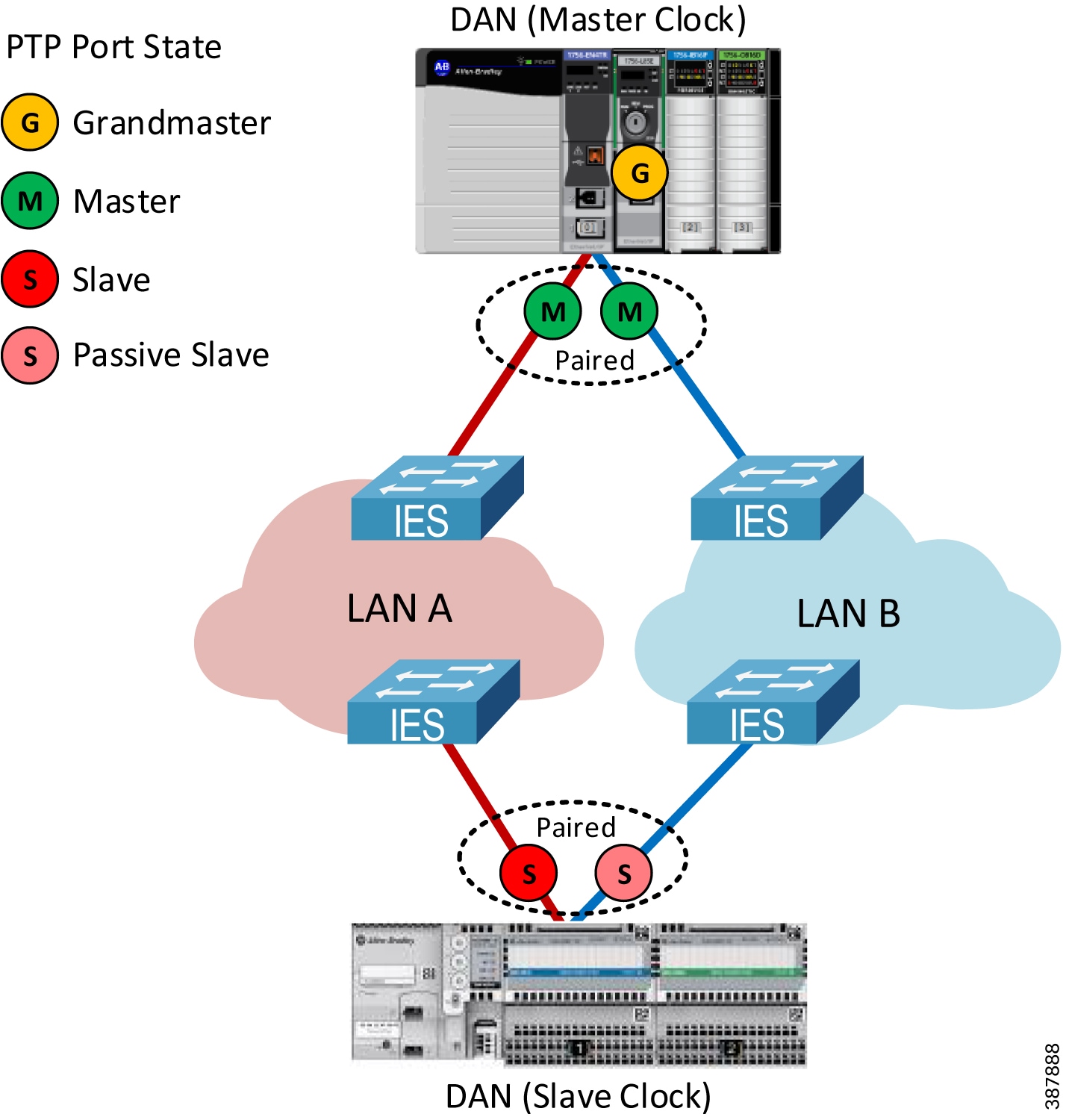
PRP networks support CIP Sync by implementing the doubly-attached clock model as specified in IEC 62439-3 standard (Figure 2-25):
- In a DAN or a RedBox with the master clock role, both ports A and B operate as CIP Sync master ports in their LAN segments.
- In a DAN or a RedBox with a slave clock role, both ports A and B are paired and function as CIP Sync slave ports.
–![]() One port is the active slave port that synchronizes to the master clock, measures path delay, and tunes the clock. This port reports its state as SLAVE.
One port is the active slave port that synchronizes to the master clock, measures path delay, and tunes the clock. This port reports its state as SLAVE.
–![]() The other port is passive and reports its state as PASSIVE_SLAVE or PASSIVE. The passive slave port also measures path delay and maintains close synchronization to the master clock. In case of a network failure on the active slave port, the passive slave port clock transitions smoothly to the active state.
The other port is passive and reports its state as PASSIVE_SLAVE or PASSIVE. The passive slave port also measures path delay and maintains close synchronization to the master clock. In case of a network failure on the active slave port, the passive slave port clock transitions smoothly to the active state.
–![]() Either LAN A or LAN B port can be chosen as active slave port depending on the Best Master Clock Algorithm (BMCA) of the PTP protocol. As a result, some DANs can be syncing over LAN A and some over LAN B infrastructure.
Either LAN A or LAN B port can be chosen as active slave port depending on the Best Master Clock Algorithm (BMCA) of the PTP protocol. As a result, some DANs can be syncing over LAN A and some over LAN B infrastructure.
–![]() Ethernet frames that carry PTP information are not duplicated and exclude the redundancy trailer.
Ethernet frames that carry PTP information are not duplicated and exclude the redundancy trailer.
–![]() PTP packets from DANs, such as Sync, Delay Request and Delay Response, are generated independently for LAN A and LAN B ports.
PTP packets from DANs, such as Sync, Delay Request and Delay Response, are generated independently for LAN A and LAN B ports.
Figure 2-25 PRP Doubly Attached Clock Model
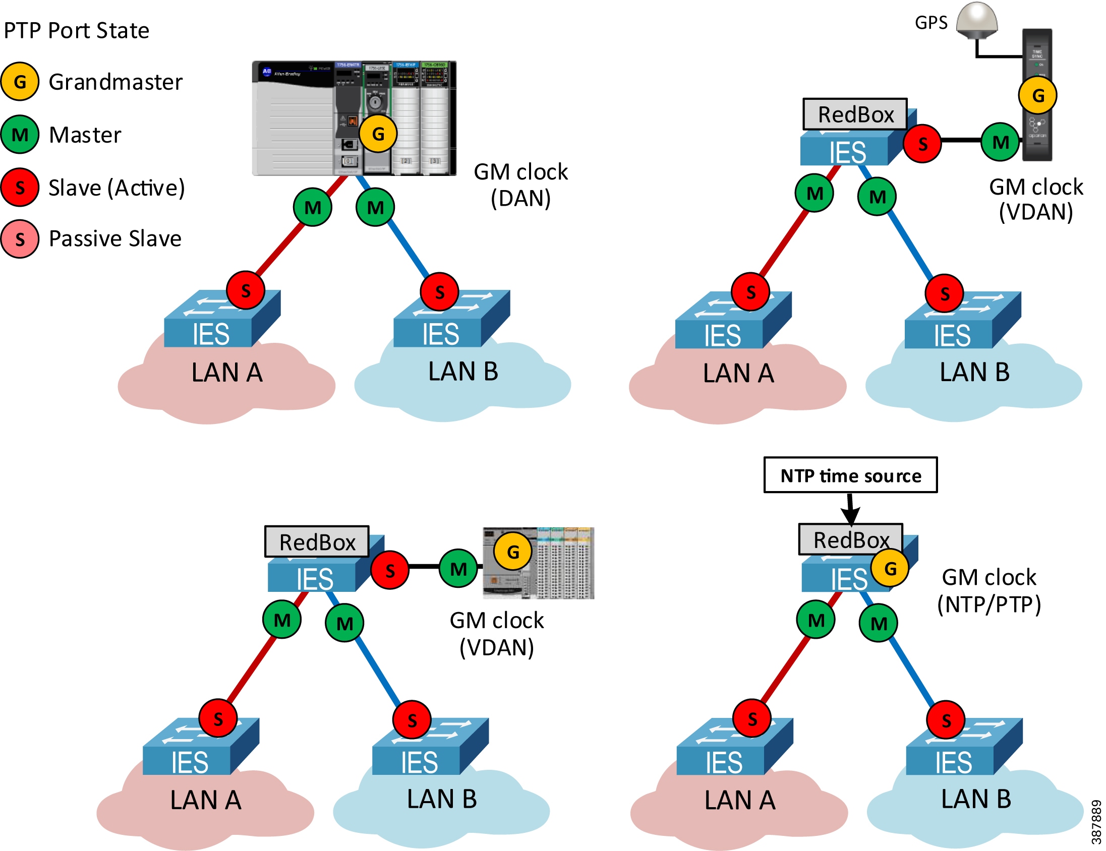
In the PTP architecture, all clocks are synchronized to a Grandmaster clock (GM). The GM must be a DAN or a VDAN and cannot be a SAN attached to LAN A or LAN B. Figure 2-26 shows some of the options for a GM in the PRP topology:
- A PAC in a chassis with an EtherNet/IP PRP module (DAN)
- A PAC (VDAN) connected to a RedBox IES
- A Global Positioning System (GPS) time module (VDAN) connected to a RedBox IES
- A RedBox IES configured as a GM in the NTP/PTP mode
Figure 2-26 Grandmaster Clock in a PRP Topology
For critical applications using time synchronization:
- Use primary and secondary grandmasters for resiliency
- Do not connect grandmasters as SANs (one in LAN A, another in LAN B).
- Implement measures to reduce the risk of grandmasters failing such as providing backup power to the grandmasters and network infrastructure
- Reduce the risk of simultaneous failures for the primary and secondary grandmasters by using separate network switches, redundant power supplies, and using multiple reference time sources.
Note![]() Switchover from a primary GM to a backup GM is a system-wide event and may cause disruptions to time synchronization.
Switchover from a primary GM to a backup GM is a system-wide event and may cause disruptions to time synchronization.
PTP Recommendations for IES
Use these guidelines for configuring IES in the CPwE PRP architecture with PTP:
- Configure Layer 2 RedBox IES as boundary clocks (BC).
- Configure Layer 3 RedBox IES as boundary clocks or as NTP/PTP clock (if RedBox IES are used as the active and backup GM).
Note![]() Transparent clock (TC) mode or forward mode are not supported on a RedBox IES.
Transparent clock (TC) mode or forward mode are not supported on a RedBox IES.
- Configure infrastructure IES in LAN A and LAN B as boundary clocks if time synchronization is required in multiple VLANs across PRP Cell/Area Zone
–![]() Use VLAN trunking for Layer 2 links between IES and make sure that the Native VLAN matches on each end of the trunk link.
Use VLAN trunking for Layer 2 links between IES and make sure that the Native VLAN matches on each end of the trunk link.
- Transparent clock mode can be used on infrastructure IES in LAN A and LAN B when only one VLAN is used for time synchronization between IACS devices connected to TC switches.
–![]() Transparent clock IES do not propagate PTP information between VLANs.
Transparent clock IES do not propagate PTP information between VLANs.
–![]() PTP VLAN ID should be configured on the boundary clock IES for ports connected to the transparent clock IES.
PTP VLAN ID should be configured on the boundary clock IES for ports connected to the transparent clock IES.
Note![]() Infrastructure IES without PTP support, or in the PTP forward mode, are allowed but not recommended due to lower time synchronization accuracy in the PRP architecture.
Infrastructure IES without PTP support, or in the PTP forward mode, are allowed but not recommended due to lower time synchronization accuracy in the PRP architecture.
CPwE PRP architecture with GPS Reference Clock
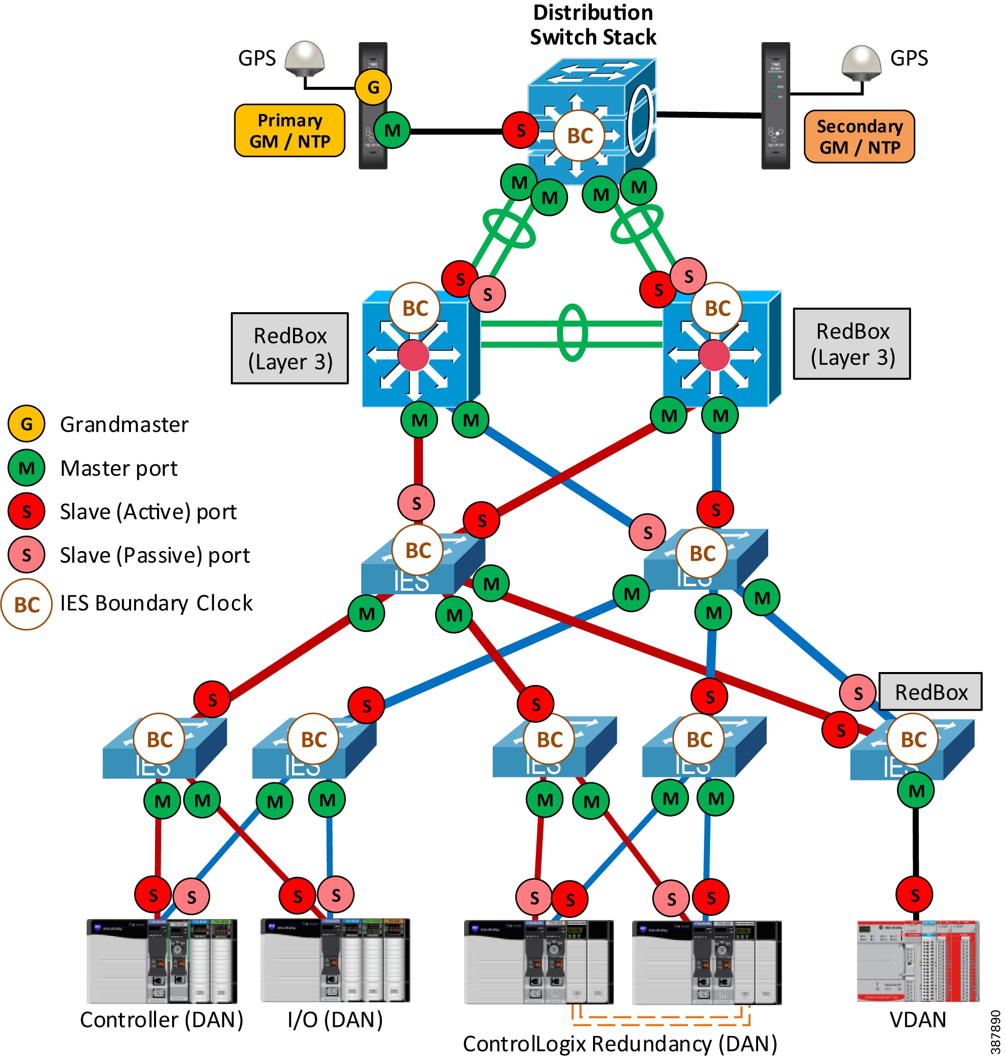
Figure 2-27 shows an example of the recommended and validated CPwE PRP architecture with redundant GPS time modules connected to the distribution switch stack.
- Time modules synchronize to GPS satellites as reference clocks and distribute time information via PTP and NTP to the plant-wide or site-wide network.
- One of the time modules is the primary GM and the primary NTP server. The second module serves as a secondary GM / NTP server in case the first module becomes unreachable.
–![]() Time modules should be connected to different switches in the distribution stack and should use separate power supplies and preferably separate GPS antennas.
Time modules should be connected to different switches in the distribution stack and should use separate power supplies and preferably separate GPS antennas.
- Cisco Catalyst 9300 switches in the distribution stack and Layer 3 RedBox IES are configured in the BC mode.
Note![]() PTP BC mode is supported with EtherChannels on the Cisco Catalyst 9300 starting with IOS XE 17.2.1 and on Stratix IES starting with IOS 15.2(7)E3
PTP BC mode is supported with EtherChannels on the Cisco Catalyst 9300 starting with IOS XE 17.2.1 and on Stratix IES starting with IOS 15.2(7)E3
- Infrastructure IES in LAN A and LAN B are configured in the BC mode to enable time synchronization in multiple VLAN.
Figure 2-27 Example of CPwE PRP architecture with PTP CIP Sync - Redundant GPS Modules
Note![]() Managed IES and other network devices use NTP for timestamping network events in logs. Both NTP and PTP must be configured in IES to correlate all events logged by the network infrastructure devices with IACS events.
Managed IES and other network devices use NTP for timestamping network events in logs. Both NTP and PTP must be configured in IES to correlate all events logged by the network infrastructure devices with IACS events.
Below are considerations and recommendations based on the CPwE PRP testing:
- In steady state with no network faults, time synchronization between IACS devices was maintained within the resolution of the CIP Sync modules used in the testing (< 8 microseconds).
- Switchover from the primary to secondary GM may cause temporary degradation of time accuracy for IACS devices. Time skew as much as 2 milliseconds between IACS devices was observed for a period of several seconds.
- Network events that change master clock for BC switches (LAN or RedBox) or change the active slave port on a DAN can cause similar PTP disturbances. This may include HSRP failover between Layer 3 RedBox IES, LAN A or LAN B switch faults, and various link faults in the network.
- It is recommended to use latest hardware series and firmware revisions for IACS devices and IES.
- 1756-EN4TR ControlLogix Ethernet modules (firmware 4.001 and later) and FLEX 5000 EtherNet/IP adapters are recommended for better CIP Sync performance during network faults.
Examples of PRP Architectures using NTP/PTP mode
If GPS time source is not available, time modules or Layer 3 RedBox IES can be configured as Grandmaster clocks in the NTP/PTP mode. In this case, time modules or RedBoxes use NTP servers in the Industrial or Enterprise Zone as reference clocks and provide PTP synchronization for the IACS devices in one or multiple Cell/Area Zones.
Figure 2-28 below shows an example of a PRP architecture with redundant time modules in NTP/PTP mode (without GPS) connected to the distribution switch stack. In this example, the time modules are the primary and secondary PTP GM and are the NTP servers for infrastructure devices in the Cell/Area Zone.
Figure 2-28 Example of PRP Architecture with Redundant NTP/PTP Module
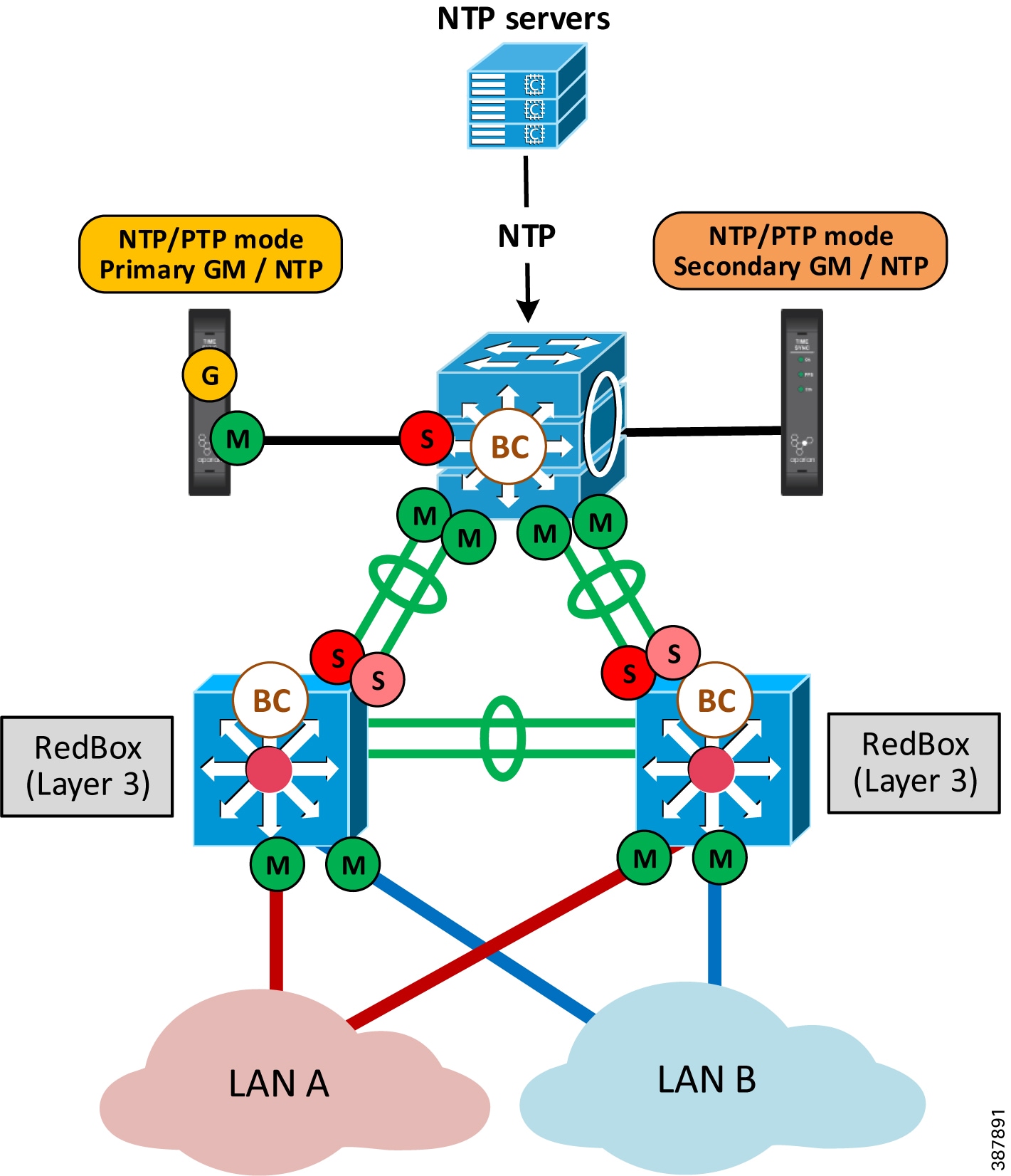
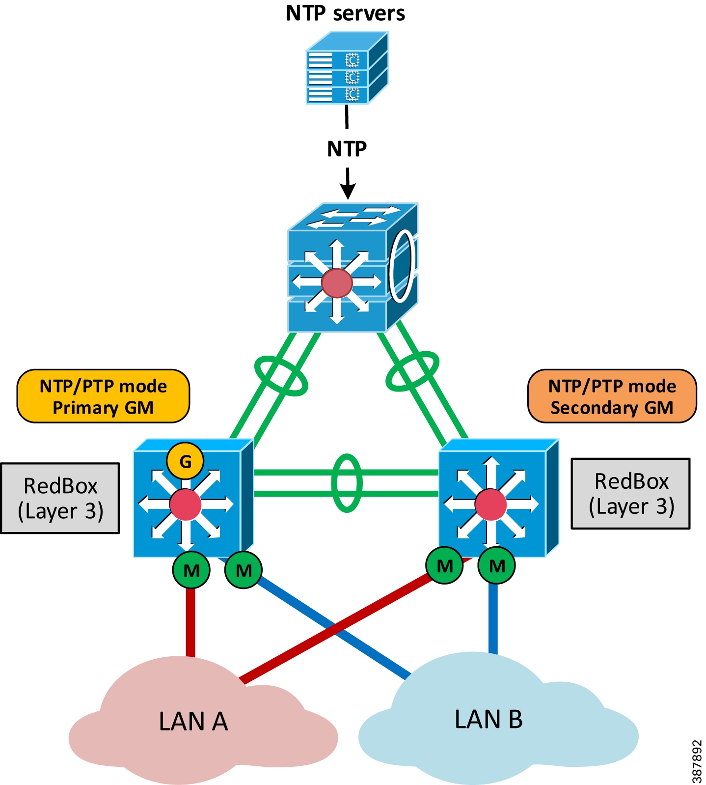
Figure 2-29 shows an example of a PRP architecture with Layer 3 RedBox IES in NTP/PTP mode. In this case, NTP is used for time distribution in the plant-wide or site-wide network, and PTP is used in each Cell/Area Zone with NTP/PTP configuration on IES.
Multiple Cell/Area Zones with PRP use separate pairs of Layer 3 RedBox IEs for NTP to PTP transition. As a result, time synchronization accuracy between IACS devices in different Cell/Area Zones depends on the accuracy that NTP can provide.
Figure 2-29 Example of PRP Architecture with NTP/PTP on RedBox IES
In both NTP/PTP architectures above, using NTP servers as reference clocks instead of GPS limits the accuracy of time synchronization. The system behavior can be impacted by network performance and availability of the NTP time sources. For example, a fault of the active NTP server and switchover to another NTP server may impact PTP time synchronization for IACS devices.
Applying PRP with IACS Applications
PRP technology is independent from the network layer or IACS application layer and therefore can be used with different types of IACS applications that require high availability. The following IACS applications and data types have been tested and validated within the CPwE PRP:
- CIP Class 1 I/O and Produced Consumed tags (unicast and multicast)
- ControlLogix Redundancy (requires version 31.052 or higher)
- CIP Class 3 messaging
- CIP Safety™
- CIP Sync and IEEE 1588 Precision Time Protocol (PTP)
- FactoryTalk View Site Edition
- FactoryTalk View Machine Edition
- FactoryTalk Linx
- Studio 5000 Logix Designer®
ControlLogix Redundancy with PRP
A ControlLogix redundancy system provides greater availability by establishing redundancy between a pair of controller chassis with identical components. ControlLogix redundancy is further enhanced by using high availability networks, such as PRP, to provide fault tolerance in the infrastructure.
CPwE PRP architecture has been tested with 5570 and 5580 ControlLogix Redundancy including redundant PAC chassis with EtherNet/IP modules (DAN) communicating to DAN or VDAN I/O devices, other PACs, and FactoryTalk applications. ControlLogix Redundancy system configuration included the following:
- EtherNet/IP PRP modules for I/O and Produced Consumed data configured for IP address swapping during a chassis switchover
- Dedicated EtherNet/IP PRP modules for HMI data that do not swap IP addresses
- Redundant ControlLogix Controller shortcut type in FactoryTalk Linx that provides paths to the Primary and Secondary controllers through the PRP modules with no IP address swapping.
- ControlLogix Redundancy firmware revision 31.052 or later; FactoryTalk Linx 6.11 or later.
- Infrastructure and RedBox IES configured for IGMP snooping as described earlier
Note![]() Routed traffic to and from the ControlLogix Redundancy (e.g., FactoryTalk data or CIP Class 3 messages between VLANs) can be affected by Layer 3 switch faults, HSRP and routing protocol convergence. These types of faults are not covered by the PRP zero data loss mechanism and should be considered independently in the PRP architecture design calculations.
Routed traffic to and from the ControlLogix Redundancy (e.g., FactoryTalk data or CIP Class 3 messages between VLANs) can be affected by Layer 3 switch faults, HSRP and routing protocol convergence. These types of faults are not covered by the PRP zero data loss mechanism and should be considered independently in the PRP architecture design calculations.
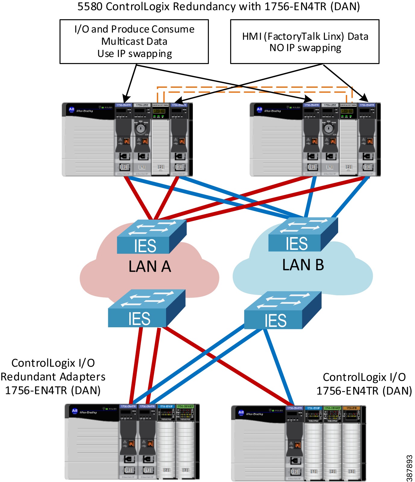
Figure 2-30 shows an example of a 5580 ControlLogix Redundancy system using PRP:
- 1756-EN4TR modules with PRP (firmware 4.001 or later) in the ControlLogix redundant controller chassis (version 34 or later)
- One pair of modules is dedicated for FactoryTalk Linx communication (no IP swapping)
- The second pair of modules is configured with IP swapping to support multicast I/O and Produce Consume traffic
- Single or redundant 1756-EN4TR modules with PRP in the remote I/O chassis
Figure 2-30 Example of 5580 ControlLogix Redundancy with PRP
For more information on using PRP with ControlLogix Redundancy, refer to:
- High Availability Systems Reference Manual https://literature.rockwellautomation.com/idc/groups/literature/documents/rm/highav-rm002_-en-p.pdf
PlantPAx Distributed Control System with PRP
The PlantPAx® Distributed Control System is an integrated control and information solution that provides Plantwide Optimization for a wide range of industries. This single-platform system is built on open industry standards to help support the seamless integration of system components, and to provide connectivity to high-level business systems.
PRP is the recommended redundancy technology for a PlantPAx system where the highest level of availability is required. A PlantPAx system design uses a CPwE PRP architecture to build a redundant network topology with infrastructure duplication, fault tolerance capability, zero recovery time within the PRP zone, and minimal recovery time for traffic leaving the PRP zone.
For more information on PlantPAx system infrastructures with PRP, refer to:
- PlantPAx Distributed Control System Configuration and Implementation User Manual https://literature.rockwellautomation.com/idc/groups/literature/documents/um/proces-um100_-en-p.pdf
- PlantPAx Distributed Control System Selection Guide https://literature.rockwellautomation.com/idc/groups/literature/documents/sg/proces-sg001_-en-p.pdf
 Feedback