About the Server Switch Module
This chapter describes the Cisco 4x InfiniBand Switch module for IBM BladeCenter. This chapter contains the following sections:
•![]() LEDs
LEDs
Introduction
The Cisco 4x InfiniBand Switch module for IBM BladeCenter (hereafter "Server Switch Module") adds InfiniBand (IB) switching capability to hosts in your IBM BladeCenter H chassis. When you add one or two Server Switch Modules to your BladeCenter chassis and add HCA expansion cards to your BladeCenter hosts, your hosts can communicate to one another over IB within the chassis. When you connect the Server Switch Module to an outside IB fabric, BladeCenter hosts can communicate with all nodes that connect to the IB network. Figure 1-1 shows the Server Switch Module.
Figure 1-1 Cisco 4x InfiniBand Switch Module for IBM BladeCenter
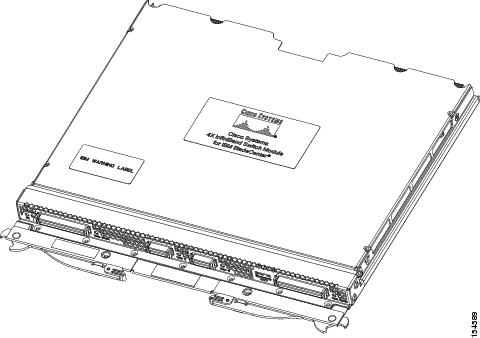
Each Server Switch Module includes 16 4x ports to the backplane and 8 4x ports (in the form of 2 4x connectors and 2 12x connectors) on the front panel. The Server Switch Module provides full non-blocking switching for all 24 ports. On the backplane, 14 of the internal 4x ports provide 10 Gbps connections to the HCA expansion cards on server blades. The two remaining internal 4x ports provide connections to the chassis expansion modules. All external 4x connectors provide 10 Gbps connections to the outside IB network and can autonegotiate connection speed.
Server Switch Modules transmit information to and from BladeCenter Management Modules over Ethernet (through an internal Ethernet switch) to facilitate setup and management. After you set up a Server Switch Module and bring it online, the on-board Cisco Subnet Manager brings distributed intelligence to the IB network.
Cisco Server Switch Modules allow you to perform a field upgrade to load the latest firmware on the Server Switch Module. You can perform a firmware upgrade even following a failed upgrade. CLI and GUI interfaces both support upgrades. For details, see the Command Line Interface Reference Guide or the Element Manager User Guide.
Server Switch Module and HCA Expansion Cards
Within the BladeCenter unit, Server Switch Modules manage traffic to and from HCA expansion cards on the BladeCenter hosts. Each HCA expansion card adds two IB ports to a BladeCenter host. Each HCA port connects through the unit backplane to a particular Server Switch Module slot. The first IB port of each HCA card (ib0) connects to the Server Switch Module in I/O slot 7, and the second IB port of each HCA card (ib1) connects to I/O slot 9. For detailed information about the HCA expansion card, see the Cisco 4x InfiniBand HCA Expansion Card for IBM BladeCenter User Guide.
Topologies
With the Server Switch Module and HCA expansion cards, you can create a non-redundant, single-switch topology or a redundant, dual-switch topology.

Note ![]() There are four I/O module bays in the switch, labelled 7-10. Bay 7 is for the first InfiniBand interface, and bay 9 is for the second InfiniBand interface. Bays 8 and 10 are not supported.
There are four I/O module bays in the switch, labelled 7-10. Bay 7 is for the first InfiniBand interface, and bay 9 is for the second InfiniBand interface. Bays 8 and 10 are not supported.
Single-Switch Topology
When you populate just one BladeCenter module slot with a Server Switch Module, you create a simple topology which provides full bandwidth between ports. However, this topology does not provide redundant links from the HCA expansion cards to the Server Switch Module. We strongly recommend that you implement a "Dual-Switch Topology" to avoid single points of failure.
Dual-Switch Topology
To enable IB redundancy on the BladeCenter chassis, you must install one Server Switch Module in each available slot. HCA expansion cards do not support redundant links to a single Server Switch Module slot. When you add a second Server Switch Module to the BladeCenter chassis, each port of each HCA expansion card connects to a Server Switch Module.
Note ![]() The Server Switch Modules do not connect to each other within the BladeCenter chassis. To connect the modules to enable features such as subnet manager failover, connect the modules with an IB cable through the external connectors. Before you connect the two Server Switch Modules in your chassis, configure the priority of the subnet managers on the modules. For step by step instructions, see the "Connecting Beyond BladeCenter" section on page 2-5.
The Server Switch Modules do not connect to each other within the BladeCenter chassis. To connect the modules to enable features such as subnet manager failover, connect the modules with an IB cable through the external connectors. Before you connect the two Server Switch Modules in your chassis, configure the priority of the subnet managers on the modules. For step by step instructions, see the "Connecting Beyond BladeCenter" section on page 2-5.
Module Management
You can manage your Server Switch Module with any of the following interfaces:
•![]() Simple Network Management Protocol (SNMP) versions 1, 2, and 3 with Cisco's Management Information Base (MIBs)
Simple Network Management Protocol (SNMP) versions 1, 2, and 3 with Cisco's Management Information Base (MIBs)
•![]() TopspinOS command line interface (CLI)
TopspinOS command line interface (CLI)
•![]() Chassis Manager Web-based GUI
Chassis Manager Web-based GUI
•![]() Element Manager Java-based GUI
Element Manager Java-based GUI
•![]() APIs (through SNMP)
APIs (through SNMP)
For instructions that show how to configure your Server Switch Module with the CLI, see the Command Line Interface Reference Guide. For instructions that show how to configure your Server Switch Module with Chassis Manager, see the Chassis Manager User Guide. For instructions that show how to configure your Server Switch Module with Element Manager, see the Element Manager User Guide.
LEDs
The Server Switch Module provides module status LEDs and port status LEDs. Table 1-1provides more information about the LEDs.
Note ![]() External port numbers begin at 17 because ports 1 through 16 are internal.
External port numbers begin at 17 because ports 1 through 16 are internal.
Table 1-1 Server Switch Module LED Status
Server Switch Module Status LEDs
Module Status LEDs provide an at-a-glance indication of the health of the Server Switch Module. The tables list and describe the states of the Module Status LEDs.
Port Status LEDs
The port LEDs on the Server Switch Module indicate connection and transmission status (see tables below). Link LEDs indicate connection status. Traffic LEDs indicate transmission status.
Table 1-2 IB 4x Port LED Status Indicators
Table 1-3 IB 12x Port LED Status Indicators
External InfiniBand Ports
The Server Switch Module has both 4x IB and 12x IB external connectors. The 12x IB connectors support three 4x connections using an "octopus cable." This cable begins as one 12x connector (which connects to your Server Switch Module), then branches into three 4x connectors that you can attach to 4x IB interfaces. The external ports are numbered 17 - 24. Ports 19 / 20 /21 and ports 22 / 23 / 24 are on 12x connectors and can be set up as 12x or three 4x connections.
 Feedback