- Preface
-
- Getting Started with Security Manager
- Preparing Devices for Management
- Managing the Device Inventory
- Managing Activities
- Managing Policies
- Managing Policy Objects
- Managing FlexConfigs
- Managing Deployment
- Troubleshooting Device Communication and Deployment
- Managing the Security Manager Server
- Configuring Security Manager Administrative Settings
-
- Introduction to Firewall Services
- Managing Identity-Aware Firewall Policies
- Managing TrustSec Firewall Policies
- Managing Firewall AAA Rules
- Managing Firewall Access Rules
- Managing Firewall Inspection Rules
- Managing Firewall Web Filter Rules
- Managing Firewall Botnet Traffic Filter Rules
- Working with ScanSafe Web Security
- Managing Zone-based Firewall Rules
- Managing Traffic Zones
- Managing Transparent Firewall Rules
- Configuring Network Address Translation
-
- Managing Site-to-Site VPNs: The Basics
- Configuring IKE and IPsec Policies
- GRE and DM VPNs
- Easy VPN
- Group Encrypted Transport (GET) VPNs
- Managing Remote Access VPNs: The Basics
- Managing Remote Access VPNs on ASA and PIX 7.0+ Devices
- Managing Dynamic Access Policies for Remote Access VPNs (ASA 8.0+ Devices)
- Managing Remote Access VPNs on IOS and PIX 6.3 Devices
- Configuring Policy Objects for Remote Access VPNs
- Using Map View
- Getting Started with IPS Configuration
- Managing IPS Device Interfaces
- Configuring Virtual Sensors
- Defining IPS Signatures
- Configuring Event Action Rules
- Managing IPS Anomaly Detection
- Configuring Global Correlation
- Configuring Attack Response Controller for Blocking and Rate Limiting
- Managing IPS Sensors
- Configuring IOS IPS Routers
-
- Managing Firewall Devices
- Configuring Bridging Policies on Firewall Devices
- Configuring Device Administration Policies on Firewall Devices
- Configuring Device Access Settings on Firewall Devices
- Configuring Failover
- Configuring Hostname, Resources, User Accounts, and SLAs
- Configuring Server Access Settings on Firewall Devices
- Configuring FXOS Server Access Settings on Firepower 2100 Series Devices
- Configuring Logging Policies on Firewall Devices
- Configuring Multicast Policies on Firewall Devices
- Configuring Routing Policies on Firewall Devices
- Configuring Security Policies on Firewall Devices
- Configuring Service Policy Rules on Firewall Devices
- Configuring Security Contexts on Firewall Devices
- User Preferences
- Index
Router Device Administration

Note![]() From version 4.17, though Cisco Security Manager continues to support IOS features/functionality, it does not support any bug fixes or enhancements.
From version 4.17, though Cisco Security Manager continues to support IOS features/functionality, it does not support any bug fixes or enhancements.
This chapter contains the following topics:
- AAA on Cisco IOS Routers
- AAA Policy Page
- User Accounts and Device Credentials on Cisco IOS Routers
- Accounts and Credential s Policy Page
- Bridging on Cisco IOS Routers
- Bridging Policy Page
- Time Zone Settings on Cisco IOS Routers
- Clock Policy Page
- CPU Utilization Settings on Cisco IOS Routers
- CPU Policy Page
- HTTP and HTTPS on Cisco IOS Routers
- HTTP Policy Page
- Line Access on Cisco IOS Routers
- Console Policy Page
- VTY Policy Page
- Optional SSH Settings on Cisco IOS Routers
- Secure Shell Policy Page
- SNMP on Cisco IOS Routers
- SNMP Policy Page
- DNS on Cisco IOS Routers
- DNS Policy Page
- Hostnames and Domain Names on Cisco IOS Routers
- Hostname Policy Page
- Memory Settings on Cisco IOS Routers
- Memory Policy Page
- Secure Device Provisioning on Cisco IOS Routers
- Secure Device Provisioning Policy Page
- DHCP on Cisco IOS Routers
- DHCP Policy Page
- NTP on Cisco IOS Routers
- NTP Policy Page
AAA on Cisco IOS Routers
Note![]() From version 4.17, though Cisco Security Manager continues to support IOS features/functionality, it does not support any bug fixes or enhancements.
From version 4.17, though Cisco Security Manager continues to support IOS features/functionality, it does not support any bug fixes or enhancements.
Authentication, authorization, and accounting (AAA) network security services provide the primary framework through which you set up access control on your Cisco IOS router. Use the AAA policy in Security Manager to enable AAA functionality on Cisco IOS routers and to configure default AAA settings. The default settings that you define in this policy can be used in other policies, such as HTTP and line access (console and VTY) policies. Enabling AAA functionality is a prerequisite for any device policy that makes use of AAA, including NAC, SDP, and 802.1x.
For more information about AAA, see:
To configure a AAA policy, see:
Supported Authorization Types
AAA authorization enables you to limit the services available to an authenticated user. Security Manager supports the following types of authorization:
- Network—Authorizes various types of network connections, such as PPP, SLIP, and ARAP.
- EXEC—Authorizes the launching of EXEC (CLI) sessions.
- Command—Authorizes the use of all EXEC mode commands that are associated with specific privilege levels.
When authorization is enabled, the router uses information retrieved from the user’s profile to configure the user session. The profiles are located either in the local user database or on a security server. Users are granted access to a requested service only if the profile allows it.
Supported Accounting Types
AAA accounting enables you to track the services the users are accessing and the amount of network resources that they are consuming. Security Manager supports the following accounting types:
- Connection—Records information about all outbound connections made from this device, such as Telnet, local-area transport (LAT), TN3270, packet assembler/disassembler (PAD), and rlogin connections.
For example, a RADIUS connection accounting record for an outbound Telnet connection includes such information as the port and IP address of the network access server (NAS), the start and end times of the connection, the identity of the user, and the number of packets that were transmitted during the session.
- EXEC—Records information about user EXEC (CLI) sessions on the devices, including the username, date, start and stop times, and the IP address of the NAS. For dial-in users, the record includes the telephone number from which the call originated.
- Command—Records information about the EXEC commands executed on the device by users with specific privilege levels. Each command accounting record includes a list of the commands executed for that privilege level, the date and time each command was executed, and the name of the user who executed it.
For each accounting type, you can choose whether you want to generate an accounting record at the start and end of each user session or only at the end.
When AAA accounting is enabled, the router sends accounting records of user activity to the TACACS+ or RADIUS security server. Each accounting record contains accounting attribute-value (AV) pairs and is stored on the security server. This data can later be analyzed for network management, client billing, and auditing purposes.
Understanding Method Lists
A method list is a sequential list describing the methods to use to perform a particular AAA function. In Security Manager, you define method lists by selecting AAA server groups, which are reusable objects that typically contain one or more AAA servers running the same protocol, such as RADIUS or TACACS+. Method lists enable you to designate one or more security protocols to be used for each AAA function, thus ensuring a backup system if the initial method fails.
Note![]() Security Manager also contains predefined AAA server group objects for using the enable password or a local database. See Predefined AAA Authentication Server Groups.
Security Manager also contains predefined AAA server group objects for using the enable password or a local database. See Predefined AAA Authentication Server Groups.
For each AAA function, the device initially uses the first method defined in the list. If that method fails to respond, the device selects the next method in the list. This process continues until there is successful communication with a listed method, or all methods defined in the method list are exhausted.
Note![]() The device attempts to communicate with the next listed method only when there is no response from the previous method. If the AAA service fails at any point in this cycle—meaning that the security server or local username database responds by denying the user access or services—the process stops and no other methods are attempted.
The device attempts to communicate with the next listed method only when there is no response from the previous method. If the AAA service fails at any point in this cycle—meaning that the security server or local username database responds by denying the user access or services—the process stops and no other methods are attempted.
Defining AAA Services
To define AAA services on a Cisco IOS router, you must first enable AAA functionality on the router. After you do this, you can define the kind of functionality (authentication, authorization, and accounting) that you want the device to implement. You must define a method list for each function, including lists for each type of authorization and accounting that you enable.
For example, if you want to configure EXEC authorization and command authorization, you must define one method list for EXEC authorization and other method lists for each privilege level on which command authorization is performed.
Note![]() If you use RADIUS for authentication, you must use the same RADIUS server group for authorization as well.
If you use RADIUS for authentication, you must use the same RADIUS server group for authorization as well.
- Understanding Method Lists
- AAA on Cisco IOS Routers
- Understanding AAA Server and Server Group Objects
Step 1![]() Do one of the following:
Do one of the following:
- (Device view) Select Platform > Device Admin > AAA from the Policy selector.
- (Policy view) Select Router Platform > Device Admin > AAA from the Policy Type selector. Select an existing policy or create a new one.
The AAA page is displayed. See AAA Policy Page for a description of the fields on this page.
Step 2![]() Define which login authentication methods to use on users who access the device:
Define which login authentication methods to use on users who access the device:
a.![]() On the Authentication tab (see AAA Page—Authentication Tab), select the Enable Device Login Authentication check box.
On the Authentication tab (see AAA Page—Authentication Tab), select the Enable Device Login Authentication check box.
b.![]() Enter the names of one or more AAA server group objects (up to four) in the Prioritized Method List field, or click Select select the object from a list or to create a new one. Use the up and down arrows in the object selector to define the order in which the selected server groups should be used.
Enter the names of one or more AAA server group objects (up to four) in the Prioritized Method List field, or click Select select the object from a list or to create a new one. Use the up and down arrows in the object selector to define the order in which the selected server groups should be used.
Note![]() If you select None as a method, it must appear as the last method in the list.
If you select None as a method, it must appear as the last method in the list.
Step 3![]() (Optional) In the Maximum Number of Attempts field, define the maximum number of unsuccessful authentication attempts to allow before a user is locked out.
(Optional) In the Maximum Number of Attempts field, define the maximum number of unsuccessful authentication attempts to allow before a user is locked out.
Step 4![]() (Optional) Define which authorization methods to use on users who have been successfully authenticated:
(Optional) Define which authorization methods to use on users who have been successfully authenticated:
a.![]() Click the Authorization tab on the AAA page. See Table 63-3 for a description of the fields on this tab.
Click the Authorization tab on the AAA page. See Table 63-3 for a description of the fields on this tab.
b.![]() Define method lists for one or more of the following types of authorization:
Define method lists for one or more of the following types of authorization:
- Network
- EXEC
- Command—Click the Add button to display the Command Authorization dialog box (see Command Authorization Dialog Box). From here, you can select a privilege level and the method list to apply to it.
For more information about these authorization types, see Supported Authorization Types.
Note![]() RADIUS uses the same server for authentication and authorization. Therefore, if you use define a RADIUS method list for authentication, you must define the same method list for authorization.
RADIUS uses the same server for authentication and authorization. Therefore, if you use define a RADIUS method list for authentication, you must define the same method list for authorization.
Step 5![]() (Optional) Define which accounting methods to use on the activities performed by users:
(Optional) Define which accounting methods to use on the activities performed by users:
a.![]() Click the Accounting tab on the AAA page. See Table 63-5 for a description of the fields on this tab.
Click the Accounting tab on the AAA page. See Table 63-5 for a description of the fields on this tab.
b.![]() Define method lists for one or more of the following types of accounting:
Define method lists for one or more of the following types of accounting:
- Connection
- EXEC
- Command—Click the Add button to display the Command Accounting dialog box (see Command Accounting Dialog Box). From here, you can select a privilege level and the method list to apply to it.
For more information about these accounting types, see Supported Accounting Types.
c.![]() For each accounting type defined above, select a value from the Accounting Process Notices list. This defines when to create an accounting record, at the beginning and end of the user process or only at the end.
For each accounting type defined above, select a value from the Accounting Process Notices list. This defines when to create an accounting record, at the beginning and end of the user process or only at the end.
d.![]() For each accounting type defined above, select the Enable broadcast to multiple servers check box if you want accounting information sent simultaneously to the first server in each AAA server group defined in the method list.
For each accounting type defined above, select the Enable broadcast to multiple servers check box if you want accounting information sent simultaneously to the first server in each AAA server group defined in the method list.
AAA Policy Page
Use the AAA page to define the default authentication, authorization, and accounting methods to use on the router. You do this by configuring method lists, which define which methods to use and the sequence in which to use them.
Note![]() You can use the method lists defined in this policy as default settings when you configure AAA on the router’s console port and VTY lines. See Console Policy Page and VTY Policy Page.
You can use the method lists defined in this policy as default settings when you configure AAA on the router’s console port and VTY lines. See Console Policy Page and VTY Policy Page.
- (Device view) Select Platform > Device Admin > AAA from the Policy selector.
- (Policy view) Select Router Platform > Device Admin > AAA from the Policy Type selector. Right-click AAA to create a policy, or select an existing policy from the Shared Policy selector.
- AAA on Cisco IOS Routers
- Understanding AAA Server and Server Group Objects
- Console Policy Page
- VTY Policy Page
|
|
|
|---|---|
Defines the login authentication methods to use and the sequence in which to use them. See AAA Page—Authentication Tab. |
|
Defines the types of network, EXEC, and command authorization to perform and the methods to use for each type. See AAA Page—Authorization Tab. |
|
Defines types of connection, EXEC, and command accounting to perform and the methods to use for each type. See AAA Page—Accounting Tab. |
AAA Page—Authentication Tab
Use the Authentication tab of the AAA page to define the methods used to authenticate users who access the device. Authentication methods are defined in a method list, which define the security protocols to use, such as LDAP, RADIUS, and TACACS+.
Note![]() You can use the method list defined in this policy on the console and VTY lines that are used to communicate with the device. See Console Policy Page and VTY Line Dialog Box—Authentication Tab.
You can use the method list defined in this policy on the console and VTY lines that are used to communicate with the device. See Console Policy Page and VTY Line Dialog Box—Authentication Tab.
Go to the AAA Policy Page, then click the Authentication tab.
- Defining AAA Services
- Understanding Method Lists
- AAA Server Group Dialog Box
- Predefined AAA Authentication Server Groups
AAA Page—Authorization Tab
Use the Authorization tab of the AAA page to define the type of authorization services to enable on the device and the methods to use for each type. Security Manager supports the following types of authorization:
- Network—Authorizes various types of network connections, such as PPP.
- EXEC—Authorizes the launching of EXEC sessions.
- Command—Authorizes the use of all EXEC mode commands that are associated with specific privilege levels.
Note![]() You can use the method lists defined in this policy on the console and VTY lines that are used to communicate with the device. See Console Policy Page and VTY Line Dialog Box—Authentication Tab.
You can use the method lists defined in this policy on the console and VTY lines that are used to communicate with the device. See Console Policy Page and VTY Line Dialog Box—Authentication Tab.
Go to the AAA Policy Page, then click the Authorization tab.
- Defining AAA Services
- Supported Authorization Types
- Understanding Method Lists
- AAA Server Group Dialog Box
- Filtering Tables
|
|
|
|---|---|
When selected, enables the authorization of network connections, such as PPP, SLIP, or ARAP connections, using the methods defined in the method list. |
|
Defines a sequential list of methods to be queried when authorizing a user. Enter the names of one or more AAA server group objects (up to four), or click Select to select them. Use the up and down arrows in the object selector to define the order in which the selected server groups should be used. If the object that you want is not listed, click the Create button to create it. The device tries initially to authorize users using the first method in the list. If that method fails to respond, the device tries the next method, and so on, until a response is received. Supported methods include LDAP, RADIUS, TACACS+, Local, and None. Note RADIUS uses the same server for authentication and authorization. Therefore, if you use define a RADIUS method list for authentication, you must define the same method list for authorization. Note If you select None as a method, it must appear as the last method in the list. |
|
When selected, this type of authorization determines whether the user is permitted to open an EXEC (CLI) session, using the methods defined in the method list. |
|
Defines a sequential list of methods to be queried when authorizing a user. Enter the names of one or more AAA server group objects (up to four), or click Select to select them. Use the up and down arrows in the object selector to define the order in which the selected server groups should be used. If the object that you want is not listed, click the Create button to create it. The device tries initially to authorize users using the first method in the list. If that method fails to respond, the device tries the next method, and so on, until a response is received. |
|
The privilege level to which the command authorization definition applies. |
|
The method list to use when authorizing users with this privilege level. |
|
Opens the Command Authorization Dialog Box. From here you can configure a command authorization definition. |
|
Opens the Command Authorization Dialog Box. From here you can edit the command authorization definition. |
|
Deletes the selected command authorization definitions from the table. |
|
Command Authorization Dialog Box
Use the Command Authorization dialog box to define which methods to use when authorizing the EXEC commands that are associated with a given privilege level. This enables you to authorize all commands associated with a specific privilege level, from 0 to 15.
From the AAA Page—Authorization Tab, click the Add button beneath the Command Authorization table.
AAA Page—Accounting Tab
Use the Accounting tab of the AAA page to define the type of accounting services to enable on the device and the methods to use for each type. Security Manager supports the following types of accounting:
- Connection—Records information about all outbound connections made from this device.
- EXEC—Records information about user EXEC sessions on the devices, including the username, date, start and stop times, and the IP address.
- Command—Records information about the EXEC commands executed on the device by users with specific privilege levels.
In addition, you use the Accounting page to determine when accounting records should be generated and whether they should be broadcast to more than one AAA server.
Note![]() You can use the method lists defined in this policy on the console and VTY lines that are used to communicate with the device. See Console Policy Page and VTY Line Dialog Box—Authentication Tab.
You can use the method lists defined in this policy on the console and VTY lines that are used to communicate with the device. See Console Policy Page and VTY Line Dialog Box—Authentication Tab.
Go to the AAA Policy Page, then click the Accounting tab.
- Defining AAA Services
- Supported Accounting Types
- Understanding Method Lists
- AAA Server Group Dialog Box
- Filtering Tables
|
|
|
|---|---|
|
|
|
When selected, enables the recording of information about outbound connections (such as Telnet) made over this device, using the methods defined in the method list. |
|
Defines when the device sends an accounting notice to the accounting server:
|
|
Defines a sequential list of methods to be queried when creating connection accounting records for a user. Enter the names of one or more AAA server group objects (up to 10 for IOS 12.4(22)T+, otherwise up to four), or click Select to select them. Use the up and down arrows in the object selector to define the order in which the selected server groups should be used. If the object that you want is not listed, click the Create button to create it. |
|
When selected, enables the sending of accounting records to multiple AAA servers. Accounting records are sent simultaneously to the first server in each AAA server group defined in the method list. If the first server is unavailable, failover occurs using the backup servers defined within that group. When deselected, accounting records are sent only to the first server in the first AAA server group defined in the method list. |
|
|
|
|
When selected, enables the recording of basic information about user EXEC sessions, using the methods defined in the method list. |
|
See description Table 43-7. |
|
Defines a sequential list of methods to be queried when creating connection accounting records for a user. Enter the names of one or more AAA server group objects (up to 10 for IOS 12.4(22)T+, otherwise up to four), or click Select to select them. Use the up and down arrows in the object selector to define the order in which the selected server groups should be used. If the object that you want is not listed, click the Create button to create it. |
|
When selected, enables the sending of accounting records to multiple AAA servers. Accounting records are sent simultaneously to the first server in each AAA server group defined in the method list. If the first server is unavailable, failover occurs using the backup servers defined within that group. |
|
|
|
|
The privilege level to which the command authorization definition applies. |
|
The points in the process where the device sends an accounting notice to the accounting server. |
|
Whether accounting records are broadcast to multiple servers simultaneously. |
|
The method list to use when authorizing users with this privilege level. |
|
Opens the Command Accounting Dialog Box. From here you can configure a command accounting definition. |
|
Opens the Command Accounting Dialog Box. From here you can edit the command accounting definition. |
|
Deletes the selected command accounting definitions from the table. |
|
Command Accounting Dialog Box
Use the Command Accounting dialog box to define which methods to use when recording information about the EXEC commands that are executed for a given privilege level. Each accounting record includes a list of the commands executed for that privilege level, as well as the date and time each command was executed, and the name of the user who executed it.
From the AAA Page—Accounting Tab, click the Add button beneath the Command Accounting table.
User Accounts and Device Credentials on Cisco IOS Routers
Accounts and credential policies define the contact information for accessing the router, including the privilege level provided to each user account. You can configure as many user accounts as required. However, the user account that Security Manager uses to connect to the router is always the one configured in the Device Properties page.
Additionally, you use device access policies to define the enable or enable secret password required to access privileged EXEC mode. This is the mode required to make any configuration changes on the router.
Note![]() If you use this policy to define a password, be careful later not to unassign this policy without assigning a replacement policy before your next deployment. If you deploy a device access policy that removes this password and the device contains a different type of password not known to Security Manager, such as a line console password, you will not be able to configure this device in the future. This is because the device reverts to this unknown password if Security Manager removes the enable password that it had previously configured.
If you use this policy to define a password, be careful later not to unassign this policy without assigning a replacement policy before your next deployment. If you deploy a device access policy that removes this password and the device contains a different type of password not known to Security Manager, such as a line console password, you will not be able to configure this device in the future. This is because the device reverts to this unknown password if Security Manager removes the enable password that it had previously configured.
Defining Accounts and Credential Policies
This procedure describes how to define a device access policy on a Cisco IOS router. If the username that you configured on the Device Properties page to connect to the router (see Viewing or Changing Device Properties) matches one of the user accounts you defined in this policy, Security Manager updates the device credentials according to your policy definition.
If you change the password for the user defined in the device properties, which Security Manager uses to deploy configurations to the device, or change the enable password, Security Manager uses the existing credentials defined in the device properties to log into the device and deploy changes. After successful deployment, the device properties are then changed to use your new settings. For more information on credentials in device properties, see Device Credentials Page.
Note![]() You can discover encrypted passwords, but any password you enter must be in clear text. If you discover an encrypted password and then modify it, the password is saved as clear text.
You can discover encrypted passwords, but any password you enter must be in clear text. If you discover an encrypted password and then modify it, the password is saved as clear text.
Step 1![]() Do one of the following:
Do one of the following:
- (Device view) Select Platform > Device Admin > Accounts and Credentials from the Policy selector.
- (Policy view) Select Router Platform > Device Admin > Accounts and Credentials from the Policy Type selector. Select an existing policy or create a new one.
The Accounts and Credentials page is displayed. See Table 63-7 for a description of the fields on this page.
Step 2![]() Enter the password for switching to privileged EXEC mode on the router:
Enter the password for switching to privileged EXEC mode on the router:
a.![]() Select Enable Password or Enable Secret Password. The Enable Secret Password option offers better security than the Enable Password option by storing the password using MD5 encryption. This option is useful in environments in which the password crosses the network or is stored on a TFTP server.
Select Enable Password or Enable Secret Password. The Enable Secret Password option offers better security than the Enable Password option by storing the password using MD5 encryption. This option is useful in environments in which the password crosses the network or is stored on a TFTP server.
Note![]() After you set an enable secret password, you can switch to an enable password only if the enable secret is disabled or an older version of Cisco IOS software is being used, such as when running an older rxboot image.
After you set an enable secret password, you can switch to an enable password only if the enable secret is disabled or an older version of Cisco IOS software is being used, such as when running an older rxboot image.
b.![]() Enter a password, then enter it again in the Confirm field. The password that you enter must be in clear text. If you are configuring the enable secret password, the password is encrypted on deployment.
Enter a password, then enter it again in the Confirm field. The password that you enter must be in clear text. If you are configuring the enable secret password, the password is encrypted on deployment.
Step 3![]() (Optional) Select the Enable Password Encryption Service check box to encrypt all passwords on the device. This includes, for example, the enable password, username passwords, authentication key passwords, console and VTY line access passwords, and BGP neighbor passwords.
(Optional) Select the Enable Password Encryption Service check box to encrypt all passwords on the device. This includes, for example, the enable password, username passwords, authentication key passwords, console and VTY line access passwords, and BGP neighbor passwords.
We recommend using this feature to help prevent unauthorized individuals from viewing the passwords in your configuration file.
Note![]() This option does not provide a high level of security and should not be used as a substitute for additional network security measures.
This option does not provide a high level of security and should not be used as a substitute for additional network security measures.
Step 4![]() To define new user accounts for the router:
To define new user accounts for the router:
a.![]() Click the Add button under the table to display the User Accounts dialog box.
Click the Add button under the table to display the User Accounts dialog box.
b.![]() Enter the details for the new user. See Table 63-8 for a description of the available fields.
Enter the details for the new user. See Table 63-8 for a description of the available fields.
c.![]() Click OK to save your definitions locally on the client and close the dialog box. Your definitions are displayed in the User Accounts table.
Click OK to save your definitions locally on the client and close the dialog box. Your definitions are displayed in the User Accounts table.
Note![]() To edit a user account, select it from the User Accounts table, then click Edit. To remove a user account, select it, then click Delete.
To edit a user account, select it from the User Accounts table, then click Edit. To remove a user account, select it, then click Delete.

Accounts and Credential s Policy Page
Use the Accounts and Credentials page to define the enable password or enable secret password assigned to the router. In addition, you can define a list of usernames that can be used to access the router.
For more information, see Defining Accounts and Credential Policies.
- (Device view) Select Platform > Device Admin > Accounts and Credentials from the Policy selector.
- (Policy view) Select Router Platform > Device Admin > Accounts and Credentials from the Policy Type selector. Right-click Accounts and Credentials to create a policy, or select an existing policy from the Shared Policy selector.
- User Accounts and Device Credentials on Cisco IOS Routers
- User Account Dialog Box
- Table Columns and Column Heading Features
- Filtering Tables
|
|
|
|---|---|
The enable secret password for entering privileged EXEC mode on the router. This option offers better security than the Enable Password option. The enable secret password can contain between 1-25 alphanumeric characters. The first character must be a letter. Spaces are allowed, but leading spaces are ignored. Question marks are also allowed. Note You can discover an encrypted password, but any password you enter must be in clear text. If you modify an encrypted password, it is saved as clear text. Note After you set an enable secret password, you can switch to an enable password only if the enable secret is disabled or an older version of Cisco IOS software is being used, such as when running an older rxboot image. |
|
The enable password for entering privileged EXEC mode on the router. The enable password can contain between 1-25 alphanumeric characters. The first character must be a letter. Spaces are allowed, but leading spaces are ignored. Question marks are also allowed. |
|
When selected, encrypts all passwords on the device, including the enable password (which is otherwise saved in clear text). For example, use this option to encrypt username passwords, authentication key passwords, console and VTY line access passwords, and BGP neighbor passwords. This command is primarily used for keeping unauthorized individuals from viewing your passwords in your configuration file. When deselected, device passwords are stored unencrypted in the configuration file. Note This option does not provide a high level of network security. You should also take additional network security measures. |
|
The username that can be used to access the router. The username must be a single word up to 64 characters in length. Spaces and quotation marks are not allowed. |
|
Indicates whether password information for the user is encrypted using MD5 encryption. |
|
Opens the User Account Dialog Box. From here you can define a user account. |
|
Opens the User Account Dialog Box. From here you can edit the selected user. |
|
User Account Dialog Box
Employ the User Account dialog box to define a username and password combination that can be used by Security Manager to access the router. You can also define the privilege level of the user account, which determines whether you can configure all commands on this router or only a subset of them.
Note![]() Remember—there may be additional user accounts defined on the router using other methods, such as the CLI.
Remember—there may be additional user accounts defined on the router using other methods, such as the CLI.
Go to the Accounts and Credential s Policy Page, then click the Add or Edit button beneath the table.
- Defining Accounts and Credential Policies
- User Accounts and Device Credentials on Cisco IOS Routers
- Understanding FlexConfig Policies and Policy Objects
Bridging on Cisco IOS Routers
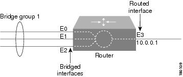
Bridging policies enable you to perform transparent bridging (as specified in RFC 1286) on selected interfaces that you have configured to function as a bridge group. Security Manager supports integrated routing and bridging, which makes it possible to route a specific protocol between routed interfaces and bridge groups, or route a specific protocol between bridge groups. Local or unroutable traffic can be bridged among the bridged interfaces in the same bridge group, while routable traffic can be routed to other routed interfaces or bridge groups, as shown in Figure 63-1.
Using integrated routing and bridging, you can:
- Switch packets from a bridged interface to a routed interface.
- Switch packets from a routed interface to a bridged interface.
- Switch packets within the same bridge group.
Figure 63-1 Transparent Bridging
Bridge-Group Virtual Interfaces
Because bridging takes places at the data link layer and routing takes place at the network layer, they have different protocol configuration models. With IP, for example, bridge group interfaces belong to the same network and have a collective IP network address. In contrast, each routed interface represents a distinct network and has its own IP network address. Integrated routing and bridging uses the concept of a bridge-group virtual interface (BVI) to enable these interfaces to exchange packets for a given protocol. As shown in Figure 63-2, the interface number assigned to the BVI corresponds to the bridge group that the BVI represents. This number serves as the link between the virtual interface and the bridge group.
Figure 63-2 Bridge-Group Virtual Interface
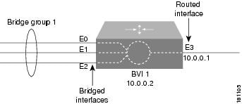
When you enable routing for a given protocol on the BVI, packets coming from a routed interface that are destined for a host in a bridged domain are routed to the BVI and then forwarded to the corresponding bridged interface. All traffic routed to the BVI is forwarded to the corresponding bridge group as bridged traffic. All routable traffic received on a bridged interface is routed to other routed interfaces as if it is coming directly from the BVI.
Note![]() BVI interfaces are configured using the Interfaces policy. See Defining Basic Router Interface Settings. The BVI interface must have a corresponding bridge group with the same number; otherwise, deployment will fail.
BVI interfaces are configured using the Interfaces policy. See Defining Basic Router Interface Settings. The BVI interface must have a corresponding bridge group with the same number; otherwise, deployment will fail.
Note![]() When the bridge group contains more than two interfaces, add a BVI interface to the group to help prevent unicast flooding, which is a potential security issue.
When the bridge group contains more than two interfaces, add a BVI interface to the group to help prevent unicast flooding, which is a potential security issue.
Defining Bridge Groups
You define a bridge group by selecting the L3 interfaces that are part of the bridge group and assigning the group a number. All bridge groups in Security Manager perform integrated routing and bridging on IP traffic only and use the standard Spanning Tree Protocol (IEEE 802.1D).
Note![]() Use CLI commands or FlexConfigs to bridge other protocols, such as AppleTalk or IPX, and to use other spanning tree protocols, such as VLAN-Bridge. Concurrent routing and bridging is not supported.
Use CLI commands or FlexConfigs to bridge other protocols, such as AppleTalk or IPX, and to use other spanning tree protocols, such as VLAN-Bridge. Concurrent routing and bridging is not supported.
Step 1![]() Do one of the following:
Do one of the following:
- (Device view) Select Platform > Device Admin > Bridging from the Policy selector.
- (Policy view) Select Router Platform > Device Admin > Bridging from the Policy Type selector. Select an existing policy or create a new one.
The Bridging page is displayed. See Table 63-9 for a description of the fields on this page.
Step 2![]() Click the Add button under the table to display the Bridge Group dialog box. See Table 63-10 for a description of the fields in this dialog box. From here you can define a bridge group.
Click the Add button under the table to display the Bridge Group dialog box. See Table 63-10 for a description of the fields in this dialog box. From here you can define a bridge group.
Step 3![]() Enter a number to identify the bridge group.
Enter a number to identify the bridge group.
Step 4![]() Enter the names of the interfaces and interface roles that are part of the bridge group, or click Select to select an interface role or to create a new one. For more information, see Specifying Interfaces During Policy Definition.
Enter the names of the interfaces and interface roles that are part of the bridge group, or click Select to select an interface role or to create a new one. For more information, see Specifying Interfaces During Policy Definition.
You can select most Layer 3 interfaces, except X.25 and Integrated Services Digital Network (ISDN) bridged interfaces and certain types of logical interfaces (such as loopback, tunnel, null, and BVI). Each interface can be included in only one bridge group.
You can select a LAN subinterface only if the parent interface is configured with Inter-Switch Link (ISL) or 802.1Q encapsulation.
Step 5![]() Click OK to save your definitions locally on the client and close the dialog box. The bridge group is displayed in the table on the Bridging page.
Click OK to save your definitions locally on the client and close the dialog box. The bridge group is displayed in the table on the Bridging page.
Note![]() To edit a bridge group, select it from the Groups table, then click Edit. To remove a bridge group, select it, then click Delete.
To edit a bridge group, select it from the Groups table, then click Edit. To remove a bridge group, select it, then click Delete.
Bridging Policy Page
Use the Bridging page to define bridge groups that can perform integrated routing and bridging on the router. For more information, see Defining Bridge Groups.
- (Device view) Select Platform > Device Admin > Bridging from the Policy selector.
- (Policy view) Select Router Platform > Device Admin > Bridging from the Policy Type selector. Right-click Bridging to create a policy, or select an existing policy from the Shared Policy selector.
|
|
|
|---|---|
The interfaces and interface roles that are included in the bridge group. |
|
Opens the Bridge Group Dialog Box. From here you can define a bridge group. |
|
Opens the Bridge Group Dialog Box. From here you can edit the bridge group. |
|
Bridge Group Dialog Box
Use the Bridge Group dialog box to define bridge groups on the router. Each bridge group can contain multiple Layer 3 interfaces of various types, including serial interfaces.
Note![]() All bridge groups use the standard Spanning Tree Protocol (IEEE 802.1D). Use CLI commands or FlexConfigs to bridge other protocols, such as AppleTalk or IPX, and to use other spanning tree protocols, such as VLAN-Bridge.
All bridge groups use the standard Spanning Tree Protocol (IEEE 802.1D). Use CLI commands or FlexConfigs to bridge other protocols, such as AppleTalk or IPX, and to use other spanning tree protocols, such as VLAN-Bridge.
Go to the Bridging Policy Page, then click the Add or Edit button beneath the table.
Time Zone Settings on Cisco IOS Routers
The local time on a Cisco IOS router is typically set using the clock set command in the CLI command or by dynamically deriving the time from an NTP server. You can adjust these time settings by defining the time zone in which the router resides and the start and end dates of Daylight Saving Time (DST) in that time zone.
Defining Time Zone and DST Settings
Security Manager enables you to define the time zone in which a Cisco IOS router is located. You can also define the start and end dates for Daylight Saving Time (DST).
Step 1![]() Do one of the following:
Do one of the following:
- (Device view) Select Platform > Device Admin > Clock from the Policy selector.
- (Policy view) Select Router Platform > Device Admin > Clock from the Policy Type selector. Select an existing policy or create a new one.
The Clock page is displayed. See Table 63-11 for a description of the fields on this page.
Step 2![]() Select the time zone in which the router is located. Time zones are listed according the number of hours behind or ahead of Greenwich Mean Time (GMT).
Select the time zone in which the router is located. Time zones are listed according the number of hours behind or ahead of Greenwich Mean Time (GMT).
Step 3![]() (Optional) Select the method for determining the start and end dates for DST:
(Optional) Select the method for determining the start and end dates for DST:
- Set by Date—Select this option when DST starts and ends on fixed dates. Continue with Step 4.
- Set by Day—Select this option when DST starts and ends on days whose specific dates vary from year to year. Continue with Step 5.
- None—Select this option when DST is not used.
Step 4![]() (When Set by Date is selected) Define the fixed dates when DST starts and ends:
(When Set by Date is selected) Define the fixed dates when DST starts and ends:
a.![]() Under Start, click the calendar icon, then click the appropriate date.
Under Start, click the calendar icon, then click the appropriate date.
b.![]() Select the hour and minute from the displayed lists.
Select the hour and minute from the displayed lists.
c.![]() Repeat steps a and b to configure the end date and time.
Repeat steps a and b to configure the end date and time.
Step 5![]() (When Set by Day is selected) Select the Specify Recurring Time check box if you want to define a DST period other than the default, which is the period used throughout most of the United States.
(When Set by Day is selected) Select the Specify Recurring Time check box if you want to define a DST period other than the default, which is the period used throughout most of the United States.
Step 6![]() (When Specify Recurring Time is selected) Define the start and end of DST:
(When Specify Recurring Time is selected) Define the start and end of DST:
a.![]() Under Start, select the month when DST begins.
Under Start, select the month when DST begins.
b.![]() Select the week of the month (1, 2, 3, 4, first, or last).
Select the week of the month (1, 2, 3, 4, first, or last).
c.![]() Select the day of the week.
Select the day of the week.
d.![]() Select the hour and minute from the displayed lists. For example, if DST begins at 1:00 a.m. on the last Sunday of each March, select March, last, Sunday, 1, and 00.
Select the hour and minute from the displayed lists. For example, if DST begins at 1:00 a.m. on the last Sunday of each March, select March, last, Sunday, 1, and 00.
e.![]() Repeat Steps a through d to configure the end date and time.
Repeat Steps a through d to configure the end date and time.
Clock Policy Page
Use the Clock page to configure the time zone in which the router is located and the settings for Daylight Saving Time (DST). For more information, see Time Zone Settings on Cisco IOS Routers.

Tip![]() You can configure the local time on the router by defining an NTP policy or by configuring the clock set command using the CLI.
You can configure the local time on the router by defining an NTP policy or by configuring the clock set command using the CLI.
- (Device view) Select Platform > Device Admin > Clock from the Policy selector.
- (Policy view) Select Router Platform > Device Admin > Clock from the Policy Type selector. Right-click Clock to create a policy, or select an existing policy from the Shared Policy selector.
|
|
|
|---|---|
The time zone in which the router is located, expressed in relation to GMT (Greenwich Mean Time), also known as UTC (Coordinated Universal Time).
|
|
The type of DST to apply to the local time on the router:
|
|
The date and time when DST ends:
Note Cisco IOS Software supports dates up to and including December 31st, 2035. |
|
When selected, the router implements DST according to the dates and times specified in this policy. When deselected, the router implements DST according to the schedule used throughout most of the United States. |
|
The relative date and time when daylight savings time begins:
For example, if DST begins at 1:00 a.m. on the last Sunday of each March, select March, last, Sunday, 1, and 00. |
|
CPU Utilization Settings on Cisco IOS Routers
The CPU policy configures settings relating to CPU utilization. This policy provides you with methods for monitoring CPU resources and tracking processes that exceed a predetermined level of utilization.
Note![]() The CPU policy is supported on routers running Cisco IOS Software Release 12.3(14)T or later.
The CPU policy is supported on routers running Cisco IOS Software Release 12.3(14)T or later.
Defining CPU Utilization Settings
You can use Security Manager to modify the following default CPU utilization settings:
- The size of the CPU history table.
- The size of the extended CPU load history table.
- Whether to enable the automatic CPU Hog profiling.
In addition, you can optionally define:
- The CPU utilization level that causes a process to be included in the history table.
- The types of CPU utilization thresholds to enable. For each type of threshold, you can determine the threshold values that trigger notifications.
Step 1![]() Do one of the following:
Do one of the following:
- (Device view) Select Platform > Device Admin > CPU from the Policy selector.
- (Policy view) Select Router Platform > Device Admin > CPU from the Policy Type selector. Select an existing policy or create a new one.
Step 2![]() (Optional) Define the CPU utilization settings of the router, as required. See Table 63-12 for a description of the available fields.
(Optional) Define the CPU utilization settings of the router, as required. See Table 63-12 for a description of the available fields.
CPU Policy Page
Use the CPU page to configure settings related to router CPU utilization, including the thresholds for sending log messages, the size of the CPU history table, and whether to enable automatic CPU Hog profiling.
For more information, see Defining CPU Utilization Settings.
- (Device view) Select Platform > Device Access > CPU from the Policy selector.
- (Policy view) Select Router Platform > Device Access > CPU from the Policy Type selector. Right-click CPU to create a policy, or select an existing policy from the Shared Policy selector.
HTTP and HTTPS on Cisco IOS Routers
Security Manager enables you to configure HTTP and HTTP over Secure Socket Layer (known as HTTP over SSL or HTTPS) server functionality on Cisco IOS routers. This feature provides SSL version 3.0 support for the HTTP 1.1 server.
A secure HTTP connection means that data sent to and received from an HTTP server are encrypted before being sent out over the internet. HTTP with SSL encryption provides a secure connection to allow such functions as configuring a router from a web browser.
In addition to providing access to the device via the Cisco web browser user interface, HTTP and HTTPS are used by device management applications, such as the Cisco Router and Security Device Manager (SDM), to communicate with the device.
Defining HTTP Policies
When you define an HTTP policy, you can:
- Enable and disable HTTP and SSL functionality on the router.
- Specify the ports used by each protocol.
- Optionally define a standard, numbered ACL that restricts access to the device using these protocols.
In addition, you can define the methods of AAA authentication and authorization methods to perform on users.
You must use caution when defining an HTTP policy, as your settings may affect communication between Security Manager (as well as other management applications that use these protocols) and the device.
Note![]() As a general rule, Cisco IOS routers that have been discovered by Security Manager already have HTTPS enabled because Security Manager uses SSL as the default protocol for communicating with them. See Setting Up SSL on Cisco IOS Routers.
As a general rule, Cisco IOS routers that have been discovered by Security Manager already have HTTPS enabled because Security Manager uses SSL as the default protocol for communicating with them. See Setting Up SSL on Cisco IOS Routers.
- Enable AAA services on the router. See Defining AAA Services.
Step 1![]() Do one of the following:
Do one of the following:
- (Device view) Select Platform > Device Admin > Device Access > HTTP from the Policy selector, then click the Setup tab in the work area.
- (Policy view) Select Router Platform > Device Admin > Device Access > HTTP from the Policy Type selector. Select an existing policy or create a new one.
The HTTP Setup tab is displayed. See Table 63-13 for a description of the fields on this tab.
Step 2![]() Select the check boxes to enable HTTP and SSL (HTTPS) server functionality on the router.
Select the check boxes to enable HTTP and SSL (HTTPS) server functionality on the router.
Note![]() If SSL is disabled (or if the HTTP policy as a whole is unassigned), Security Manager cannot communicate with the device after deployment unless you change the transport protocol for this device to SSH. This setting can be found in Device Properties. See Managing Device Communication Settings and Certificates.
If SSL is disabled (or if the HTTP policy as a whole is unassigned), Security Manager cannot communicate with the device after deployment unless you change the transport protocol for this device to SSH. This setting can be found in Device Properties. See Managing Device Communication Settings and Certificates.
Tip We recommend that you disable HTTP when SSL is enabled. This is required to ensure only secure connections to the server.
Step 3![]() (Optional) Modify the default ports used by HTTP (80) and HTTPS (443).
(Optional) Modify the default ports used by HTTP (80) and HTTPS (443).
Step 4![]() (Optional) In the Allow Connection From field, enter the name of the standard, numbered ACL object that specifies which addresses can use HTTP and HTTPS on this device, or click Select to select the ACL object from a list or to create a new one. Use this option to restrict access to these protocols. For more information about creating standard ACL objects, see Creating Standard Access Control List Objects
(Optional) In the Allow Connection From field, enter the name of the standard, numbered ACL object that specifies which addresses can use HTTP and HTTPS on this device, or click Select to select the ACL object from a list or to create a new one. Use this option to restrict access to these protocols. For more information about creating standard ACL objects, see Creating Standard Access Control List Objects
Note![]() Make sure that the ACL you select permits the Security Manager server; otherwise, communication with the device is lost.
Make sure that the ACL you select permits the Security Manager server; otherwise, communication with the device is lost.
Step 5![]() (Optional) On the AAA tab, modify the default type of authentication to perform on users who attempt to access the device using HTTP or HTTPS. Options include AAA, Enable Password (default), Local Database, and TACACS.
(Optional) On the AAA tab, modify the default type of authentication to perform on users who attempt to access the device using HTTP or HTTPS. Options include AAA, Enable Password (default), Local Database, and TACACS.
If you select AAA, continue with Step 6; otherwise, continue with Step 8.
Note![]() The TACACS option applies only to devices using an IOS software version prior to 12.3(8).
The TACACS option applies only to devices using an IOS software version prior to 12.3(8).
See Table 63-14 for a description of the fields on the AAA tab.
Step 6![]() Select the authentication method to perform on users:
Select the authentication method to perform on users:
- If you want to use the default AAA login authentication methods defined in the device’s AAA policy (see Defining AAA Services), do not select the Enable Device Login Authentication check box. Continue with Step 7.
- If you want to define a method list especially for this policy, do the following:
a.![]() Select the Enable Device Login Authentication check box.
Select the Enable Device Login Authentication check box.
b.![]() Under Prioritized Method List, enter the names of the AAA server groups to use for authentication, or click Select to select the AAA server groups from a list or to create new ones. Use the up and down arrows in the selector to define the order in which you want to apply these authentication methods.
Under Prioritized Method List, enter the names of the AAA server groups to use for authentication, or click Select to select the AAA server groups from a list or to create new ones. Use the up and down arrows in the selector to define the order in which you want to apply these authentication methods.
Note![]() Make sure that Security Manager users are defined on the AAA servers; otherwise communication with the device is lost.
Make sure that Security Manager users are defined on the AAA servers; otherwise communication with the device is lost.
Step 7![]() Select the authorization method to perform on users who use HTTP or HTTPS to begin an EXEC session:
Select the authorization method to perform on users who use HTTP or HTTPS to begin an EXEC session:
- If you want to use the default AAA authorization methods defined in the device’s AAA policy, do not select the Enable CLI/EXEC Operations Authorization check box. Continue with Step 8.
- If you want to define a method list especially for this policy, select the Enable CLI/EXEC Operations Authorization check box, then define the method list.
Note![]() If you leave this option deselected, make sure that EXEC authorization is enabled in the router’s AAA policy. Otherwise, you will be unable to connect to the device via HTTP or HTTPS (SSL). This applies to Security Manager as well as other applications, such as SDM. See Defining AAA Services.
If you leave this option deselected, make sure that EXEC authorization is enabled in the router’s AAA policy. Otherwise, you will be unable to connect to the device via HTTP or HTTPS (SSL). This applies to Security Manager as well as other applications, such as SDM. See Defining AAA Services.
Step 8![]() (Optional) Create command authorization definitions for specific privilege levels:
(Optional) Create command authorization definitions for specific privilege levels:
a.![]() Click the Add button under the Command Authorization Override table. The Command Authorization Override dialog box is displayed. See Table 63-15 for a description of the fields in this dialog box.
Click the Add button under the Command Authorization Override table. The Command Authorization Override dialog box is displayed. See Table 63-15 for a description of the fields in this dialog box.
b.![]() Configure the command authorization definition as required.
Configure the command authorization definition as required.
c.![]() Click OK. The dialog box closes and the authorization method is displayed in the Command Authorization Override table.
Click OK. The dialog box closes and the authorization method is displayed in the Command Authorization Override table.
d.![]() Repeat a. through c. to create additional command authorization definitions.
Repeat a. through c. to create additional command authorization definitions.
HTTP Policy Page
Use the HTTP page to configure HTTP and HTTPS access on the router. You can configure HTTP policies on a Cisco IOS router from the following tabs on the HTTP policy page:
For more information, see HTTP and HTTPS on Cisco IOS Routers.
- (Device view) Select Platform > Device Admin > Device Access > HTTP from the Policy selector.
- (Policy view) Select Router Platform > Device Admin > Device Access > HTTP from the Policy Type selector. Right-click HTTP to create a policy, or select an existing policy from the Shared Policy selector.
HTTP Page—Setup Tab
Use the Setup tab of the HTTP page to enable HTTP and HTTP over Secure Socket Layer (HTTP over SSL or HTTPS) on the router. You can optionally limit access to these protocols to the addresses defined in an access control list.
Note![]() As a general rule, Cisco IOS routers that have been discovered by Security Manager already have HTTPS enabled because Security Manager uses SSL as the default protocol for communicating with them. See Setting Up SSL on Cisco IOS Routers.
As a general rule, Cisco IOS routers that have been discovered by Security Manager already have HTTPS enabled because Security Manager uses SSL as the default protocol for communicating with them. See Setting Up SSL on Cisco IOS Routers.
Go to the HTTP Policy Page, then click the Setup tab.
HTTP Page—AAA Tab
Use the AAA tab of the HTTP page to define the authentication and authorization methods to perform on users who attempt to access the router using HTTP or HTTPS.
Go to the HTTP Policy Page, then click the AAA tab.
|
|
|
|---|---|
The type of authentication to use:
|
|
Applies only when AAA is selected as the authentication method. When selected, authentication is based on the methods defined in the Prioritized Method List field. When deselected, the default authentication list defined in the router’s AAA policy is used. See AAA Page—Authentication Tab. |
|
Applies only when the Enable Device Login Authentication check box is selected. Defines a sequential list of methods to be queried when authenticating a user. Enter the names of one or more AAA server group objects (up to four), or click Select to select them. Use the up and down arrows in the object selector to define the order in which the selected server groups should be used. If the object that you want is not listed, click the Create button to create it. The device tries initially to authenticate users using the first method in the list. If that method fails to respond, the device tries the next method, and so on, until a response is received. Note If you select None as a method, it must appear as the last method in the list. |
|
Applies only when AAA is selected as the authentication method. When selected, EXEC authorization is based on the methods defined in the Prioritized Method List field. This type of authorization determines whether the user is permitted to open an EXEC (CLI) session. When deselected, the default EXEC authorization list defined in the router’s AAA policy is used. See AAA Page—Authorization Tab. Note If you leave this option deselected, make sure that EXEC authorization is enabled in the router’s AAA policy. Otherwise, you will be unable to connect to the device via HTTP or HTTPS (SSL). This applies to Security Manager as well as other applications, such as SDM and the device’s web interface. |
|
Applies only when the Enable CLI/EXEC Operations Authorization check box is selected. Defines a sequential list of methods to be queried when authorizing a user to open an EXEC (CLI) session. Enter the names of one or more AAA server group objects (up to four), or click Select to select them. Use the up and down arrows in the object selector to define the order in which the selected server groups should be used. If the object that you want is not listed, click the Create button to create it. The device tries initially to authorize users using the first method in the list. If that method fails to respond, the device tries the next method, and so on, until a response is received. Note If you select None as a method, it must appear as the last method in the list. |
|
The privilege level to which the command authorization definition applies. |
|
The method list to use when authorizing users with this privilege level. |
|
Opens the Command Authorization Override Dialog Box. From here you can configure a command authorization definition. |
|
Opens the Command Authorization Override Dialog Box. From here you can edit the command authorization definition. |
|
Deletes the selected command authorization definitions from the table. |
|
Command Authorization Override Dialog Box
Use the Command Authorization Override dialog box to define which methods to use when authorizing the EXEC commands that are associated with a given privilege. This enables you to authorize all commands associated with a specific privilege level, from 0 to 15.
From the HTTP Page—AAA Tab, click the Add button beneath the Command Authorization Override table.
Line Access on Cisco IOS Routers
Security Manager enables you to configure command line access (also called EXEC access) to a router using the following methods:
- Console port—Physical connection via a standard RS232 cable for local access. For more information, see:
–![]() Defining Console Port Setup Parameters
Defining Console Port Setup Parameters
–![]() Defining Console Port AAA Settings
Defining Console Port AAA Settings
- VTY lines—Virtual terminal lines for remote access, typically using protocols such as Telnet, SSH, or rlogin. For more information, see:
–![]() Defining VTY Line Setup Parameters
Defining VTY Line Setup Parameters
–![]() Defining VTY Line AAA Settings
Defining VTY Line AAA Settings
After you configure and deploy these policies, you can use these lines to communicate with individual devices directly when you want to configure or diagnose them using the CLI.
Defining Console Port Setup Parameters
The console port on a router is generally used for local system access by an administrator with physical access to the device. By default, the console port is set up as follows:
- All permitted users have privileged access to the router, including all configuration commands (privilege level 15).
- The line is disconnected after 10 minutes without user input.
- Incoming connections are not permitted.
- Outgoing connections support Telnet only.
In addition to modifying any of the default settings, you can optionally define the following settings:
- The password for accessing the console.
- Whether to disable all EXEC sessions on the console.
- Incoming and outgoing ACLs that restrict the connections that are permitted on the console.
- Whether VRF connections are permitted on the console.
Step 1![]() Do one of the following:
Do one of the following:
- (Device view) Select Platform > Device Admin > Device Access > Line Access > Console from the Policy selector, then click the Setup tab in the work area.
- (Policy view) Select Router Platform > Device Admin > Device Access > Line Access > Console from the Policy Type selector. Select an existing policy or create a new one, and then click the Setup tab.
The Console Setup tab is displayed. See Table 63-16 for a description of the fields on this tab.
Step 2![]() (Optional) Enter the password for accessing the console port, then enter it again in the Confirm field.
(Optional) Enter the password for accessing the console port, then enter it again in the Confirm field.
Step 3![]() (Optional) Modify the default (15) granted to users of the console port. See Console Page—Authorization Tab.
(Optional) Modify the default (15) granted to users of the console port. See Console Page—Authorization Tab.
Step 4![]() (Optional) Select the Disable all the EXEC sessions to the router via this line check box to prevent any incoming connections via the console.
(Optional) Select the Disable all the EXEC sessions to the router via this line check box to prevent any incoming connections via the console.
Note![]() Selecting this option blocks all access to the device via the console port.
Selecting this option blocks all access to the device via the console port.
Step 5![]() (Optional) Modify the default timeout after which the line is disconnected if no user input is detected.
(Optional) Modify the default timeout after which the line is disconnected if no user input is detected.
Note![]() Setting this value to 0 disables the timeout. Disabling the timeout could compromise the security of your network.
Setting this value to 0 disables the timeout. Disabling the timeout could compromise the security of your network.
Step 6![]() (Optional) Specify which protocols can be used for outbound connections on the console port:
(Optional) Specify which protocols can be used for outbound connections on the console port:
- All—All supported protocols are permitted.
- None—No protocols are permitted.
- Protocol—Enables one or more of the following protocols: SSH, Telnet, and rlogin.
Note![]() You must configure AAA authentication on devices where the console port permits the SSH and rlogin protocols. See Defining Console Port AAA Settings.
You must configure AAA authentication on devices where the console port permits the SSH and rlogin protocols. See Defining Console Port AAA Settings.
Step 7![]() (Optional) Enter the names of ACLs that restrict incoming and outgoing connections between the device and the addresses in these lists, or click Select to select the ACL object or to create a new one. At the top of the selector, in the Type field, select the ACL type as either Standard or Extended.
(Optional) Enter the names of ACLs that restrict incoming and outgoing connections between the device and the addresses in these lists, or click Select to select the ACL object or to create a new one. At the top of the selector, in the Type field, select the ACL type as either Standard or Extended.
Step 8![]() (Optional) Click the AAA tab to define authentication, authorization, and accounting settings for the console port. See Defining Console Port AAA Settings.
(Optional) Click the AAA tab to define authentication, authorization, and accounting settings for the console port. See Defining Console Port AAA Settings.
Defining Console Port AAA Settings
By default, authentication, authorization, and accounting are not performed on the console port. When you configure one or more of these access control options, you can either make use of the default method lists defined in the device’s AAA policy or define a custom method list containing one or more AAA methods.
Step 1![]() Do one of the following:
Do one of the following:
- (Device view) Select Platform > Device Admin > Device Access > Line Access > Console from the Policy selector, then click the Authentication tab in the work area.
- (Policy view) Select Router Platform > Device Admin > Device Access > Line Access > Console from the Policy Type selector. Select an existing policy or create a new one, and then click the Authentication tab.
The Console Authentication tab is displayed.
Step 2![]() (Optional) Select the authentication method to perform on users who attempt to access the console line.
(Optional) Select the authentication method to perform on users who attempt to access the console line.
See Table 63-17 for a description of the fields on the Authentication tab.
Note![]() If you select local authentication, preview the full configuration before deployment to make sure that the aaa new-model command is not configured by another policy (for example, by configuring a method list in the AAA policy) or is already configured on the device itself.
If you select local authentication, preview the full configuration before deployment to make sure that the aaa new-model command is not configured by another policy (for example, by configuring a method list in the AAA policy) or is already configured on the device itself.
Step 3![]() (Optional) On the Authorization tab, select the authorization method to perform on users who access the console line and begin an EXEC session.
(Optional) On the Authorization tab, select the authorization method to perform on users who access the console line and begin an EXEC session.
See Table 63-18 for a description of the fields on the Authorization tab.
Note![]() RADIUS uses the same server for authentication and authorization. Therefore, if you use define a RADIUS method list for authentication, you must define the same method list for authorization.
RADIUS uses the same server for authentication and authorization. Therefore, if you use define a RADIUS method list for authentication, you must define the same method list for authorization.
Step 4![]() (Optional) Create command authorization definitions for specific privilege levels:
(Optional) Create command authorization definitions for specific privilege levels:
a.![]() Click the Add button under the Commands Authorization table. The Command Authorization dialog box is displayed. See Table 63-26 for details.
Click the Add button under the Commands Authorization table. The Command Authorization dialog box is displayed. See Table 63-26 for details.
b.![]() Configure the command authorization definition as required.
Configure the command authorization definition as required.
c.![]() Click OK. The dialog box closes and the authorization method is displayed in the Commands Authorization table.
Click OK. The dialog box closes and the authorization method is displayed in the Commands Authorization table.
d.![]() Repeat a. through c. to create additional command authorization definitions.
Repeat a. through c. to create additional command authorization definitions.
Step 5![]() (Optional) On the Accounting tab, select the EXEC and connection accounting methods to perform on users who access the console line.
(Optional) On the Accounting tab, select the EXEC and connection accounting methods to perform on users who access the console line.
See Table 63-19 for a description of the fields on this tab.
Step 6![]() (Optional) Create command accounting definitions for specific privilege levels:
(Optional) Create command accounting definitions for specific privilege levels:
a.![]() Click the Add button under the Commands Accounting table. The Command Accounting Dialog Box—Line Access is displayed.
Click the Add button under the Commands Accounting table. The Command Accounting Dialog Box—Line Access is displayed.
b.![]() Configure the command accounting definition as required.
Configure the command accounting definition as required.
c.![]() Click OK. The dialog box closes and the accounting method is displayed in the Commands Accounting table.
Click OK. The dialog box closes and the accounting method is displayed in the Commands Accounting table.
d.![]() Repeat a. through c. to create additional command accounting definitions.
Repeat a. through c. to create additional command accounting definitions.
Defining VTY Line Setup Parameters
All Cisco IOS routers are configured by default with five VTY lines (labeled 0-4) that have the following settings:
- All permitted users have privileged access to the router, including all configuration commands (privilege level 15).
- VTY lines are disconnected after 10 minutes without user input.
- Incoming connections are not permitted.
- Outgoing connections support Telnet only.
You can use Security Manager to modify the default settings on these five VTY lines or to configure additional lines (up to a maximum of 16). In addition, you can optionally configure the following settings on each line:
- The password for accessing the line.
- Whether to disable all EXEC sessions on the line.
- Incoming and outgoing ACLs that restrict the connections that are permitted on the line.
- Whether VRF connections are permitted on the line.
You can configure multiple VTY lines as a contiguous group, which enables you to define identical settings for all the lines in the group with one procedure. All the lines within the group must fall within one of two ranges, 0-4 or 6-15. The group cannot overlap these two ranges.
The rules for configuring VTY line 5 are as follows. Line 5 can be part of the same definition as lines 0-4 only when there are no lines configured above line 5. If there are lines configured above line 5, you cannot include line 5 in the definition for lines 0-4, even if their configurations are the same. Line 5 can be included in the definition of the lines above line 5 if their configurations are the same.
For example, if lines 0-5 all share one configuration and lines 6-9 have a different configuration, you need to create three definitions—one definition for lines 0-4, a second definition for line 5, and a third definition for lines 6-9.
Note![]() When you configure VTY lines, bear in mind that users are assigned a line at random when they connect to the device.
When you configure VTY lines, bear in mind that users are assigned a line at random when they connect to the device.
Note![]() You can create only one definition per VTY line. An error is displayed if you create a VTY line definition that overlaps an existing definition.
You can create only one definition per VTY line. An error is displayed if you create a VTY line definition that overlaps an existing definition.
Note![]() If you use Security Manager to configure the default VTY lines (0-4), your definition overrides the default settings on the device. If you later delete this definition from Security Manager, the input protocol settings are retained and the other default settings are restored. This ensures that you always have VTY lines available for remote access to the device.
If you use Security Manager to configure the default VTY lines (0-4), your definition overrides the default settings on the device. If you later delete this definition from Security Manager, the input protocol settings are retained and the other default settings are restored. This ensures that you always have VTY lines available for remote access to the device.
Note![]() You can use the CLI or FlexConfigs to configure additional VTY lines on devices that support more than 16 lines.
You can use the CLI or FlexConfigs to configure additional VTY lines on devices that support more than 16 lines.
Step 1![]() Do one of the following:
Do one of the following:
- (Device view) Select Platform > Device Admin > Device Access > Line Access > VTY from the Policy selector.
- (Policy view) Select Router Platform > Device Admin > Device Access > Line Access > VTY from the Policy Type selector. Select an existing policy or create a new one.
The VTY page is displayed. See Table 63-20 for a description of the fields on this page.
Step 2![]() Click the Add button beneath the Lines table, or select a line definition and then click the Edit button. The Setup tab of the VTY Lines dialog box is displayed. See Table 63-21 for a description of the fields on this tab.
Click the Add button beneath the Lines table, or select a line definition and then click the Edit button. The Setup tab of the VTY Lines dialog box is displayed. See Table 63-21 for a description of the fields on this tab.
Step 3![]() Enter the relative line number of the VTY line. If you are configuring a group of VTY lines, enter the first and last numbers of the group in the fields provided.
Enter the relative line number of the VTY line. If you are configuring a group of VTY lines, enter the first and last numbers of the group in the fields provided.
Step 4![]() (Optional) Enter the password for accessing the console line, then enter it again in the Confirm field.
(Optional) Enter the password for accessing the console line, then enter it again in the Confirm field.
Step 5![]() (Optional) Modify the default Privilege (15) granted to users of this VTY line (or group of lines).
(Optional) Modify the default Privilege (15) granted to users of this VTY line (or group of lines).
Step 6![]() (Optional) Select the Disable all the EXEC sessions to the router via this line check box to prevent any incoming connections over this VTY line (or group of lines).
(Optional) Select the Disable all the EXEC sessions to the router via this line check box to prevent any incoming connections over this VTY line (or group of lines).
Step 7![]() (Optional) Modify the default timeout after which the line is disconnected if no user input is detected.
(Optional) Modify the default timeout after which the line is disconnected if no user input is detected.
Note![]() Setting this value to 0 to disables the timeout. Disabling the timeout could cause abandoned sessions to block available VTY lines. It can also compromise the security of your network.
Setting this value to 0 to disables the timeout. Disabling the timeout could cause abandoned sessions to block available VTY lines. It can also compromise the security of your network.
Step 8![]() (Optional) Specify which protocols can be used for inbound and outbound connections on this VTY line (or group of lines):
(Optional) Specify which protocols can be used for inbound and outbound connections on this VTY line (or group of lines):
- All—All supported protocols are permitted.
- None—No protocols are permitted.
- Protocol—Enables one or more of the following protocols: SSH, Telnet, and rlogin.
Note![]() You must configure AAA authentication when the VTY line permits the SSH and rlogin protocols. See Defining VTY Line AAA Settings.
You must configure AAA authentication when the VTY line permits the SSH and rlogin protocols. See Defining VTY Line AAA Settings.
Step 9![]() (Optional) Enter the names of ACLs that restrict incoming and outgoing connections between the device and the addresses in these lists, or click Select to select an ACL object from a list or to create a new one. You can choose from standard or extended ACLs.
(Optional) Enter the names of ACLs that restrict incoming and outgoing connections between the device and the addresses in these lists, or click Select to select an ACL object from a list or to create a new one. You can choose from standard or extended ACLs.
Tip Defining an inbound ACL is a good way to reserve a VTY line for administrative access only.
Step 10![]() (Optional) Click the AAA tab to define authentication, authorization, and accounting settings for this VTY line (or group of lines). See Defining VTY Line AAA Settings.
(Optional) Click the AAA tab to define authentication, authorization, and accounting settings for this VTY line (or group of lines). See Defining VTY Line AAA Settings.
Step 11![]() Click OK to save your definitions locally on the client and close the dialog box. Your definitions are displayed in the Lines table.
Click OK to save your definitions locally on the client and close the dialog box. Your definitions are displayed in the Lines table.
Note![]() To remove a VTY line definition, select it, then click Delete. If you delete a VTY line from an IOS device, any subsequent lines are also deleted. For example, if the device contains lines 0-9 and you delete line 5, lines 6-9 are deleted as well. If you delete the definition for lines 0-4 from Security Manager, the router retains the inbound protocol definition and restores the other default settings for these lines on the device. This ensures that five VTY lines are always available.
To remove a VTY line definition, select it, then click Delete. If you delete a VTY line from an IOS device, any subsequent lines are also deleted. For example, if the device contains lines 0-9 and you delete line 5, lines 6-9 are deleted as well. If you delete the definition for lines 0-4 from Security Manager, the router retains the inbound protocol definition and restores the other default settings for these lines on the device. This ensures that five VTY lines are always available.
Defining VTY Line AAA Settings
By default, authentication, authorization, and accounting are not performed on VTY lines. When you configure one or more of these access control options, you can either make use of the default method lists defined in the device’s AAA policy or define a custom method list containing one or more AAA methods.
- Define the basic parameters of the VTY line or group of VTY lines. See Defining VTY Line Setup Parameters.
Step 1![]() Do one of the following:
Do one of the following:
- (Device view) Select Platform > Device Admin > Device Access > Line Access > VTY from the Policy selector.
- (Policy view) Select Router Platform > Device Admin > Device Access > Line Access > VTY from the Policy Type selector. Select an existing policy or create a new one.
The VTY page is displayed. See Table 63-20 for a description of the fields on this page.
Step 2![]() Select a VTY line definition in the Lines tables, click the Edit button to display the VTY Line dialog box, then click the Authentication tab.
Select a VTY line definition in the Lines tables, click the Edit button to display the VTY Line dialog box, then click the Authentication tab.
Step 3![]() (Optional) Select the authentication method to perform on users who attempt to access the VTY line.
(Optional) Select the authentication method to perform on users who attempt to access the VTY line.
See Table 63-23 for a description of the fields on this tab.
Note![]() If you select local authentication, preview the full configuration before deployment to make sure that the aaa new-model command is not configured by another policy (for example, by configuring a method list in the AAA policy) or is already configured on the device itself.
If you select local authentication, preview the full configuration before deployment to make sure that the aaa new-model command is not configured by another policy (for example, by configuring a method list in the AAA policy) or is already configured on the device itself.
Step 4![]() (Optional) On the Authorization tab, select the authorization method to perform on users who access the VTY line and begin an EXEC session.
(Optional) On the Authorization tab, select the authorization method to perform on users who access the VTY line and begin an EXEC session.
See Table 63-24 for a description of the fields on the Authorization tab.
Note![]() RADIUS uses the same server for authentication and authorization. Therefore, if you use define a RADIUS method list for authentication, you must define the same method list for authorization.
RADIUS uses the same server for authentication and authorization. Therefore, if you use define a RADIUS method list for authentication, you must define the same method list for authorization.
Step 5![]() (Optional) Create command authorization definitions for specific privilege levels:
(Optional) Create command authorization definitions for specific privilege levels:
a.![]() Click the Add button under the Commands Authorization table. The Command Authorization Dialog Box—Line Access is displayed.
Click the Add button under the Commands Authorization table. The Command Authorization Dialog Box—Line Access is displayed.
b.![]() Configure the command authorization definition as required.
Configure the command authorization definition as required.
c.![]() Click OK. The dialog box closes and the authorization method is displayed in the Commands Authorization table.
Click OK. The dialog box closes and the authorization method is displayed in the Commands Authorization table.
d.![]() Repeat a. through c. to create additional command authorization definitions.
Repeat a. through c. to create additional command authorization definitions.
Step 6![]() (Optional) On the Accounting tab, select the EXEC and connection accounting methods to perform on users who attempt to access the VTY line.
(Optional) On the Accounting tab, select the EXEC and connection accounting methods to perform on users who attempt to access the VTY line.
See Table 63-25 for a description of the fields on the Accounting tab.
Step 7![]() (Optional) Create command accounting definitions for specific privilege levels:
(Optional) Create command accounting definitions for specific privilege levels:
a.![]() Click the Add button under the Commands Accounting table. The Command Accounting Dialog Box—Line Access is displayed.
Click the Add button under the Commands Accounting table. The Command Accounting Dialog Box—Line Access is displayed.
b.![]() Configure the command accounting definition as required.
Configure the command accounting definition as required.
c.![]() Click OK. The dialog box closes and the accounting method is displayed in the Commands Accounting table.
Click OK. The dialog box closes and the accounting method is displayed in the Commands Accounting table.
d.![]() Repeat a. through c. to create additional command accounting definitions.
Repeat a. through c. to create additional command accounting definitions.
Console Policy Page
Use the Console page to configure access to the router over the console port. You can configure console policies on a Cisco IOS router from the following tabs on the Console policy page:
- Console Page—Setup Tab
- Console Page—Authentication Tab
- Console Page—Authorization Tab
- Console Page—Accounting Tab
For more information, see Line Access on Cisco IOS Routers.
- (Device view) Select Platform > Device Admin > Device Access > Line Access > Console from the Policy selector.
- (Policy view) Select Router Platform > Device Admin > Device Access > Line Access > Console from the Policy Type selector. Right-click Console to create a policy, or select an existing policy from the Shared Policy selector.
Console Page—Setup Tab
Use the Setup tab of the Console page to define the basic parameters of the console port. This includes the password for accessing the port, the privilege level assigned to users, the protocols that are permitted, and the ACLs that limit access.
Go to the Console Policy Page, then click the Setup tab.
- Console Page—Authentication Tab
- Console Page—Authorization Tab
- Console Page—Accounting Tab
- VTY Line Dialog Box—Setup Tab
|
|
|
|---|---|
The password for accessing the console port. The password is case sensitive and can contain up to 80 alphanumeric characters. The first character cannot be a number. Spaces are not allowed. |
|
The privilege level assigned to users connected to the console port. Valid values range from 0 to 15:
Note Levels 2-14 are not normally used in a default configuration, but custom configurations can be created by moving commands that are normally at level 15 to a lower level and commands that are normally at level 1 to a higher level. You can configure the privilege levels of commands using the CLI or by defining a FlexConfig. Note If you do not define a value, level 1 is assigned by default. This value does not appear in the device configuration. |
|
When selected, disables EXEC sessions over this line. Select this option when you want to allow only an outgoing connection on the console. This option is useful for keeping the console port free from unsolicited incoming data that can tie up the line. When deselected, EXEC sessions are enabled on the console port. This is the default. Note Selecting this option blocks all access to the device via the console port. |
|
The amount of time (in seconds) that the EXEC command interpreter waits to detect user input on the console port. If no input is detected, the line is disconnected. Valid values range from 0 to 2147483. The default is 600 (10 minutes). Setting the value to 0 disables the timeout. Note Although the timeout is defined in seconds, it appears in the CLI in the format [mm ss]. |
|
The protocols that you can use for outgoing connections on the console port:
– – Note SSH and rlogin require that you configure AAA authentication. See Console Page—Authentication Tab. Note Not all IOS Software Versions support rlogin as an output protocol. |
|
The name of the ACL object that restricts incoming connections on the console port. Enter the name of the ACL object, or click Select to select it. If the object that you want is not listed, click the Create button to create it. |
|
Applies only when an inbound ACL is defined on the console port. When selected, accepts incoming connections from interfaces that belong to a VRF. When deselected, rejects incoming connections from interfaces that belong to a VRF. |
|
The name of the ACL object that restricts outgoing connections on the console port. Enter the name of an ACL object, or click Select to select it. If the object that you want is not listed, click the Create button to create it. |
Console Page—Authentication Tab
Use the Authentication tab of the Console page to define the AAA authentication methods to perform on users who attempt to access the console port.
Go to the Console Policy Page, then click the Authentication tab.
- Console Page—Setup Tab
- Console Page—Authorization Tab
- Console Page—Accounting Tab
- VTY Line Dialog Box—Authentication Tab
|
|
|
|---|---|
Authentication settings for the console port:
Note If you select local authentication, preview the full configuration before deployment to make sure that the aaa new-model command is not configured by another policy (for example, by configuring a method list in the AAA policy) or is already configured on the device itself. |
|
Applies only when Custom Method List is selected as the authentication method. Defines a sequential list of methods to be queried when authenticating a user. Enter the names of one or more AAA server group objects (up to four), or click Select to select them. Use the up and down arrows in the object selector to define the order in which the selected server groups should be used. If the object that you want is not listed, click the Create button to create it. The device tries initially to authenticate users using the first method in the list. If that method fails to respond, the device tries the next method, and so on, until a response is received. Note If you select None as a method, it must appear as the last method in the list. |
Console Page—Authorization Tab
Use the Authorization tab of the Console page to define the EXEC and command authorization methods to perform on users who access the console port.
Note![]() You must enable AAA services on the router to use this feature; otherwise, deployment will fail. See Defining AAA Services.
You must enable AAA services on the router to use this feature; otherwise, deployment will fail. See Defining AAA Services.
Go to the Console Policy Page, then click the Authorization tab.
- Console Page—Setup Tab
- Console Page—Authentication Tab
- Console Page—Accounting Tab
- VTY Line Dialog Box—Authorization Tab
- Filtering Tables
|
|
|
|---|---|
The authorization method that determines whether a user is allowed to run an EXEC session:
|
|
Applies only when Custom Method List is selected as the EXEC method. Defines a sequential list of methods to be queried when authorizing a user. Enter the names of one or more AAA server group objects (up to four), or click Select to select them. Use the up and down arrows in the object selector to define the order in which the selected server groups should be used. If the object that you want is not listed, click the Create button to create it. The device tries initially to authorize users using the first method in the list. If that method fails to respond, the device tries the next method, and so on, until a response is received. Note If you select None as a method, it must appear as the last method in the list. Note RADIUS uses the same server for authentication and authorization. Therefore, if you use define a RADIUS method list for authentication, you must define the same method list for authorization. |
|
The privilege level to which the command authorization definition applies. |
|
The method list to use when authorizing users with this privilege level. |
|
Opens the Command Authorization Dialog Box—Line Access. From here you can configure a command authorization definition. |
|
Opens the Command Authorization Dialog Box—Line Access. From here you can edit the command authorization definition. |
|
Deletes the selected command authorization definitions from the table. |
|
Console Page—Accounting Tab
Use the Accounting tab of the Console page to define the EXEC, connection, and command accounting methods to perform on users who access the console port.
Note![]() You must enable AAA services on the router to use this feature; otherwise, deployment will fail. See Defining AAA Services.
You must enable AAA services on the router to use this feature; otherwise, deployment will fail. See Defining AAA Services.
Go to the Console Policy Page, then click the Accounting tab.
- Console Page—Setup Tab
- Console Page—Authentication Tab
- Console Page—Authorization Tab
- VTY Line Dialog Box—Accounting Tab
- Filtering Tables
|
|
|
|---|---|
The accounting method to use for recording basic information about user EXEC sessions:
EXEC accounting records basic details about EXEC sessions, such as the username, date, start and stop times, and the access server IP address. |
|
Applies only when Custom Method List is selected as the EXEC method. Defines when the device sends an accounting notice to the accounting server:
|
|
Applies only when Custom Method List is selected as the EXEC method. Defines a sequential list of methods to be queried when creating accounting methods for a user. Enter the names of one or more AAA server group objects (up to four), or click Select to select them. Use the up and down arrows in the object selector to define the order in which the selected server groups should be used. If the object that you want is not listed, click the Create button to create it. The device tries initially to perform accounting using the first method in the list. If that method fails to respond, the device tries the next method, and so on, until a response is received. Note If you select None as a method, it must appear as the last method in the list. |
|
Applies only when Method List is selected as the EXEC method. When selected, enables the sending of accounting records to multiple AAA servers. Accounting records are sent simultaneously to the first server in each AAA server group defined in the method list. If the first server is unavailable, failover occurs using the backup servers defined within that group. When deselected, accounting records are sent only to the first server in the first AAA server group defined in the method list. |
|
The accounting method to use for recording information about outbound connections made over the console line:
Connection accounting records details about outgoing connections over the line, such as Telnet and rlogin connections. |
|
Applies only when Custom Method List is selected as the connection method. Defines when the device sends an accounting notice to the accounting server:
|
|
Applies only when Custom Method List is selected as the connection method. Defines a sequential list of methods to be queried when creating accounting methods for a user. Enter the names of one or more AAA server group objects (up to four), or click Select to select them. Use the up and down arrows in the object selector to define the order in which the selected server groups should be used. If the object that you want is not listed, click the Create button to create it. The device tries initially to perform accounting using the first method in the list. If that method fails to respond, the device tries the next method, and so on, until a response is received. Note If you select None as a method, it must appear as the last method in the list. |
|
Applies only when Custom Method List is selected as the connection method. When selected, enables the sending of accounting records to multiple AAA servers. Accounting records are sent simultaneously to the first server in each AAA server group defined in the method list. If the first server is unavailable, failover occurs using the backup servers defined within that group. When deselected, accounting records are sent only to the first server in the first AAA server group defined in the method list. |
|
The privilege level to which the command authorization definition applies. |
|
The points in the process where the device sends an accounting notice to the accounting server. |
|
Whether accounting records are broadcast to multiple servers simultaneously. |
|
The method list to use when authorizing users with this privilege level. |
|
Opens the Command Accounting Dialog Box—Line Access. From here you can configure a command accounting definition. |
|
Opens the Command Accounting Dialog Box—Line Access. From here you can edit the command accounting definition. |
|
Deletes the selected command accounting definitions from the table. |
|
VTY Policy Page
Use the VTY page to configure up to 16 VTY lines for remote access to the router. In addition to configuring individual lines, you can configure a group of lines that share the same definition.
For more information, see Line Access on Cisco IOS Routers.
- (Device view) Select Platform > Device Admin > Device Access > Line Access > VTY from the Policy selector.
- (Policy view) Select Router Platform > Device Admin > Device Access > Line Access > VTY from the Policy Type selector. Right-click VTY to create a policy, or select an existing policy from the Shared Policy selector.
|
|
|
|---|---|
The relative line number of the VTY line. This field may also contain multiple VTY lines configured as a contiguous group. |
|
The protocols that you can use for incoming connections on the VTY line. |
|
The protocols that you can use for outgoing connections on the VTY line. |
|
The amount of time the EXEC command interpreter waits until user input is detected. |
|
Opens the VTY Line Dialog Box. From here you can define a VTY line or line group. |
|
Opens the VTY Line Dialog Box. From here you can edit the VTY line or line group. |
|
Deletes the selected VTY lines from the table. If you delete a VTY line from an IOS device, any subsequent lines are also deleted. For example, if the device contains lines 0-9 and you delete line 5, lines 6-9 are deleted as well. Note If you delete any of the default VTY lines (0-4) on the device, the input protocol settings are retained and the other default settings are restored. This helps prevent you from cutting off remote access to the device. |
|
VTY Line Dialog Box
Use the VTY Line dialog box to configure one or more VTY lines (up to 16) that enable remote users to access the router. When you configure a VTY line, you can define the type of authentication and authorization to perform on users who access the lines.
Go to the VTY Policy Page, then click the Add or Edit button beneath the table.
|
|
|
|---|---|
Defines the basic configuration of the VTY line or line group. See VTY Line Dialog Box—Setup Tab. |
|
Defines the type of AAA authentication to perform on users who access the VTY line. See VTY Line Dialog Box—Authentication Tab. |
|
Defines the types of AAA authorization to perform on users who access the VTY line. See VTY Line Dialog Box—Authorization Tab. |
|
Defines the types of AAA accounting to perform on users who access the VTY line. See VTY Line Dialog Box—Accounting Tab. |
VTY Line Dialog Box—Setup Tab
Use the Setup tab of the VTY Line dialog box to define the basic parameters of the VTY line. This includes the password for accessing the line, the privilege level assigned to users, the protocols that are permitted on the line, and the ACLs that limit access.
Go to the VTY Line Dialog Box, then click the Setup tab.
- Defining VTY Line Setup Parameters
- VTY Line Dialog Box—Authentication Tab
- VTY Line Dialog Box—Authorization Tab
- VTY Line Dialog Box—Accounting Tab
- Console Page—Setup Tab
|
|
|
|---|---|
The relative line number of the VTY line. If you are configuring a group of VTY lines, enter the number of the first line in the group. Valid values range from 0 to 15. Note Although different routers support a different number of VTY lines (from four to several thousand), Security Manager supports a maximum of 16 lines per device. You cannot configure the same line number more than once. |
|
Applies only when configuring a group of lines. The relative line number of the last VTY line in the group. Note When you configure a group of lines, all the lines in the group must fall within one of two ranges, 0-4 or 6-15. |
|
The password for accessing this VTY line. The password is case sensitive and can contain up to 80 alphanumeric characters. The first character cannot be a number. Spaces are not allowed. |
|
The privilege level assigned to users on this VTY line. Valid values range from 0 to 15:
Note Levels 2-14 are not normally used in a default configuration, but custom configurations can be created by moving commands that are normally at level 15 to a lower level and commands that are normally at level 1 to a higher level. You can configure the privilege levels of commands using the CLI or by defining a FlexConfig. Note If you do not define a value, level 1 is assigned by default. This value does not appear in the device configuration. |
|
When selected, EXEC sessions are disabled over this line. Select this option when you want to allow only an outgoing connection on this line. This option is useful for keeping a particular line free from unsolicited incoming data that can tie up the line. When deselected, EXEC sessions are enabled over this line. This is the default. |
|
The amount of time (in seconds) that the EXEC command interpreter waits to detect user input on the line. If no input is detected, the line is disconnected. Valid values range from 0 to 2147483. The default is 600 (10 minutes). Setting the value to 0 disables the timeout. Note Although the timeout is defined in seconds, it appears in the CLI in the format [mm ss]. |
|
The protocols that you can use for incoming connections on this line:
Note Setting the input protocols setting to None might prevent Security Manager from connecting to the device after deployment. The device can still be managed using SSL, if SSL is enabled in the HTTP policy. See HTTP Page—Setup Tab. – – Note SSH and rlogin require that you configure AAA authentication. See VTY Line Dialog Box—Authentication Tab. Note Not all IOS Software Versions support rlogin as an input protocol. |
|
The protocols that you can use for outgoing connections on this line:
– – Note SSH and rlogin require that you configure AAA authentication. See VTY Line Dialog Box—Authentication Tab. Note Not all IOS Software Versions support rlogin as an output protocol. |
|
The name of the ACL object that restricts incoming connections on this line. Enter the name of the ACL object, or click Select to select it. If the object that you want is not listed, click the Create button to create it. |
|
Applies only when an inbound ACL is defined on this line. When selected, accepts incoming connections from interfaces that belong to a VRF. When deselected, rejects incoming connections from interfaces that belong to a VRF. |
|
The name of the ACL object that restricts outgoing connections on this line. Enter the name of the ACL object, or click Select to select it. If the object that you want is not listed, click the Create button to create it. |
VTY Line Dialog Box—Authentication Tab
Use the Authentication tab of the VTY Line dialog box to define the authentication methods to perform on users who attempt to access the selected VTY line or group of lines.
Go to the VTY Line Dialog Box, then click the Authentication tab.
- Defining VTY Line AAA Settings
- VTY Line Dialog Box—Setup Tab
- VTY Line Dialog Box—Authorization Tab
- VTY Line Dialog Box—Accounting Tab
- Console Page—Authentication Tab
|
|
|
|---|---|
Authentication settings for the VTY line:
Note If you select local authentication, preview the full configuration before deployment to make sure that the aaa new-model command is not configured by another policy (for example, by configuring a method list in the AAA policy) or is already configured on the device itself. |
|
Applies only when Custom Method List is selected as the authentication method. Defines a sequential list of methods to be queried when authenticating a user. Enter the names of one or more AAA server group objects (up to four), or click Select to select them. Use the up and down arrows in the object selector to define the order in which the selected server groups should be used. If the object that you want is not listed, click the Create button to create it. The device tries initially to authenticate users using the first method in the list. If that method fails to respond, the device tries the next method, and so on, until a response is received. Note If you select None as a method, it must appear as the last method in the list. |
VTY Line Dialog Box—Authorization Tab
Use the Authorization tab of the VTY Line dialog box to define the EXEC and command authorization methods to perform on users who access the selected VTY line or group of lines.
Note![]() You must enable AAA services on the router to use this feature; otherwise, deployment will fail. See Defining AAA Services.
You must enable AAA services on the router to use this feature; otherwise, deployment will fail. See Defining AAA Services.
Go to the VTY Line Dialog Box, then click the Authorization tab.
- Defining VTY Line AAA Settings
- VTY Line Dialog Box—Setup Tab
- VTY Line Dialog Box—Authentication Tab
- VTY Line Dialog Box—Accounting Tab
- Console Page—Authentication Tab
- Filtering Tables
|
|
|
|---|---|
The authorization method that determines whether a user is allowed to run an EXEC session:
|
|
Applies only when Custom Method List is selected as the EXEC method. Defines a sequential list of methods to be queried when authorizing a user. Enter the names of one or more AAA server group objects (up to four), or click Select to select them. Use the up and down arrows in the object selector to define the order in which the selected server groups should be used. If the object that you want is not listed, click the Create button to create it. The device tries initially to authorize users using the first method in the list. If that method fails to respond, the device tries the next method, and so on, until a response is received. Note If you select None as a method, it must appear as the last method in the list. Note RADIUS uses the same server for authentication and authorization. Therefore, if you use define a RADIUS method list for authentication, you must define the same method list for authorization. |
|
The privilege level to which the command authorization definition applies. |
|
The method list to use when authorizing users with this privilege level. |
|
Opens the Command Authorization Dialog Box—Line Access. From here you can configure a command authorization definition. |
|
Opens the Command Authorization Dialog Box—Line Access. From here you can edit the command authorization definition. |
|
Deletes the selected command authorization definitions from the table. |
|
VTY Line Dialog Box—Accounting Tab
Use the Accounting tab of the VTY Line dialog box to define the EXEC, connection, and command accounting methods to perform on users who access the selected VTY line or group of lines.
Note![]() You must enable AAA services on the router to use this feature; otherwise, deployment will fail. See Defining AAA Services.
You must enable AAA services on the router to use this feature; otherwise, deployment will fail. See Defining AAA Services.
Go to the VTY Line Dialog Box, then click the Accounting tab.
- Defining VTY Line AAA Settings
- VTY Line Dialog Box—Setup Tab
- VTY Line Dialog Box—Authentication Tab
- Console Page—Accounting Tab
- Filtering Tables
|
|
|
|---|---|
The accounting method to use for recording basic information about user EXEC sessions:
EXEC accounting records basic details about EXEC sessions, such as the username, date, start and stop times, and the access server IP address. |
|
Applies only when Custom Method List is selected as the EXEC method. Defines when the device sends an accounting notice to the accounting server:
|
|
Applies only when Custom Method List is selected as the EXEC method. Defines a sequential list of methods to be queried when creating accounting methods for a user. Enter the names of one or more AAA server group objects (up to four), or click Select to select them. Use the up and down arrows in the object selector to define the order in which the selected server groups should be used. If the object that you want is not listed, click the Create button to create it. The device tries initially to perform accounting using the first method in the list. If that method fails to respond, the device tries the next method, and so on, until a response is received. Note If you select None as a method, it must appear as the last method in the list. |
|
Applies only when Method List is selected as the EXEC method. When selected, enables the sending of accounting records to multiple AAA servers. Accounting records are sent simultaneously to the first server in each AAA server group defined in the method list. If the first server is unavailable, failover occurs using the backup servers defined within that group. When deselected, accounting records are sent only to the first server in the first AAA server group defined in the method list. |
|
The accounting method to use for recording information about outbound connections made over the VTY line:
Connection accounting records details about outgoing connections over the line, such as Telnet and rlogin connections. |
|
Applies only when Custom Method List is selected as the connection method. Defines when the device sends an accounting notice to the accounting server:
|
|
Applies only when Custom Method List is selected as the connection method. Defines a sequential list of methods to be queried when creating accounting methods for a user. Enter the names of one or more AAA server group objects (up to four), or click Select to select them. Use the up and down arrows in the object selector to define the order in which the selected server groups should be used. If the object that you want is not listed, click the Create button to create it. The device tries initially to perform accounting using the first method in the list. If that method fails to respond, the device tries the next method, and so on, until a response is received. Note If you select None as a method, it must appear as the last method in the list. |
|
Applies only when Custom Method List is selected as the connection method. When selected, enables the sending of accounting records to multiple AAA servers. Accounting records are sent simultaneously to the first server in each AAA server group defined in the method list. If the first server is unavailable, failover occurs using the backup servers defined within that group. When deselected, accounting records are sent only to the first server in the first AAA server group defined in the method list. |
|
The privilege level to which the command authorization definition applies. |
|
The points in the process where the device sends an accounting notice to the accounting server. |
|
Whether accounting records are broadcast to multiple servers simultaneously. |
|
The method list to use when authorizing users with this privilege level. |
|
Opens the Command Accounting Dialog Box—Line Access. From here you can configure a command accounting definition. |
|
Opens the Command Accounting Dialog Box—Line Access. From here you can edit the command accounting definition. |
|
Deletes the selected command accounting definitions from the table. |
|
Command Authorization Dialog Box—Line Access
Use the Command Authorization dialog box to define which methods to use when authorizing the EXEC commands that are associated with a given privilege. This enables you to authorize all commands associated with a specific privilege level, from 0 to 15.
From the Console Page—Authorization Tab or the VTY Line Dialog Box—Authorization Tab, click the Add button beneath the Command Authorization table.
|
|
|
|---|---|
The privilege level for which you want to define a command authorization list. Valid values range from 0 to 15. Note If you do not define a value, level 1 is assigned by default. This value does not appear in the device configuration. |
|
Select this option to apply the default authorization list defined in the device’s AAA policy to the EXEC commands associated with this privilege level. See Command Accounting Dialog Box. |
|
Select this option to define an authorization method list for this privilege level. |
|
Applies only when the Custom Method List option is selected. Defines a sequential list of methods to be queried when authorizing a user. Enter the names of one or more AAA server group objects (up to four), or click Select to select them. Use the up and down arrows in the object selector to define the order in which the selected server groups should be used. If the object that you want is not listed, click the Create button to create it. The device tries initially to authorize users using the first method in the list. If that method fails to respond, the device tries the next method, and so on, until a response is received. Note If you select None as a method, it must appear as the last method in the list. |
Command Accounting Dialog Box—Line Access
Use the Command Accounting dialog box to define which methods to use when recording information about the EXEC commands that are executed for a given privilege. Each accounting record includes a list of the commands executed for that privilege level, as well as the date and time each command was executed, and the name of the user who executed it.
From the Console Page—Accounting Tab or the VTY Line Dialog Box—Accounting Tab, click the Add button beneath the Command Accounting table.
Optional SSH Settings on Cisco IOS Routers
Secure Shell (SSH) is an application and a protocol that uses encryption to provide secure communication between a client and server. You can use SSH to connect remotely to a Cisco IOS router over a VTY line and establish an EXEC session. SSH is the recommended replacement for other protocols, such as Telnet and rlogin, in environments where security is a concern.
All Cisco IOS routers are required to have SSH configured before they can be added to Security Manager. This is because Security Manager uses SSH (in addition to SSL) to communicate with them. The SSH policy provides a way to modify selected default settings and configure selected optional settings.
Defining Optional SSH Settings
SSH is configured by default with the following settings:
- Both SSH version 1 and SSH version 2 are supported.
- The negotiation phase is terminated if not completed successfully after 120 seconds.
- The router tries 3 times to authenticate SSH clients before disconnecting.
You can use Security Manager to modify these default settings and optionally configure the following settings:
- The source interface for SSH packets.
- The name of the RSA key pair to use.
- Whether to regenerate the key during the next deployment.
- Make sure that SSH is enabled on the router. See Chapter 2, “Preparing Devices for Management”.
- Make sure that the VTY lines on the router allow inbound SSH traffic. See Defining VTY Line Setup Parameters.
- Make sure that a hostname and domain name are configured on the router (unless you plan to use a different RSA key pair). You can use the CLI or the Hostname policy in Security Manager for this purpose. See Hostnames and Domain Names on Cisco IOS Routers.
Step 1![]() Do one of the following:
Do one of the following:
- (Device view) Select Platform > Device Admin > Device Access > Secure Shell from the Policy selector.
- (Policy view) Select Router Platform > Device Admin > Device Access > Secure Shell from the Policy Type selector. Select an existing policy or create a new one.
The Secure Shell page is displayed. See Table 63-28 for a description of the fields on this page.
Step 2![]() (Optional) Modify the following default settings:
(Optional) Modify the following default settings:
a.![]() The version of SSH to support.
The version of SSH to support.
b.![]() The timeout for completing the negotiation phase of the SSH connection.
The timeout for completing the negotiation phase of the SSH connection.
c.![]() The number of times to attempt authentication of the SSH client.
The number of times to attempt authentication of the SSH client.
Step 3![]() (Optional) In the Source Interface field, enter the name of the interface or interface role whose address should be used as the source interface for all SSH packets sent to SSH clients, or click Select to select an interface role object from a list or to create a new one. The source interface must have an IP address.
(Optional) In the Source Interface field, enter the name of the interface or interface role whose address should be used as the source interface for all SSH packets sent to SSH clients, or click Select to select an interface role object from a list or to create a new one. The source interface must have an IP address.
If you do not enter a value in this field, the address of the closest interface to the destination is used.
Step 4![]() (Optional) Enter the name of the RSA key pair to use for SSH connections. If you do not enter a value in this field, the router uses the key pair that is based on the hostname and domain name.
(Optional) Enter the name of the RSA key pair to use for SSH connections. If you do not enter a value in this field, the router uses the key pair that is based on the hostname and domain name.
Tip Use the CLI command show crypto key mypubkey rsa to display the names and values of each key pair configured on the device.
Step 5![]() (Optional) Select the Regenerate Key During Deployment check box if you want the router to regenerate the RSA key pair used for SSH. This option is useful if you believe that the secrecy of the keys might be compromised. Enter the size of the modulus to use to regenerate the keys.
(Optional) Select the Regenerate Key During Deployment check box if you want the router to regenerate the RSA key pair used for SSH. This option is useful if you believe that the secrecy of the keys might be compromised. Enter the size of the modulus to use to regenerate the keys.
Note![]() You must remember to return to this policy after deployment to deselect the check box. If you do not do this, a new key is generated during each deployment.
You must remember to return to this policy after deployment to deselect the check box. If you do not do this, a new key is generated during each deployment.
Note![]() This option requires interaction with the device during deployment. Therefore, you should use it only when deploying to live devices, not when deploying to a file.
This option requires interaction with the device during deployment. Therefore, you should use it only when deploying to live devices, not when deploying to a file.
Note![]() A key pair must already exist on the device before you select this option; otherwise, deployment will fail. (This will typically be the case, since IOS routers must have SSH enabled to be added to Security Manager.)
A key pair must already exist on the device before you select this option; otherwise, deployment will fail. (This will typically be the case, since IOS routers must have SSH enabled to be added to Security Manager.)
Secure Shell Policy Page
Use the Secure Shell page to change the default SSH settings on the router and to define additional optional settings, if required.
For more information, see Optional SSH Settings on Cisco IOS Routers.
Note![]() You must configure SSH on the device using CLI commands before adding the device to Security Manager. This is because Security Manager uses SSH (as well as SSL) to communicate with Cisco IOS routers. For more information, see Setting Up SSH.
You must configure SSH on the device using CLI commands before adding the device to Security Manager. This is because Security Manager uses SSH (as well as SSL) to communicate with Cisco IOS routers. For more information, see Setting Up SSH.
- (Device view) Select Platform > Device Admin > Device Access > Secure Shell from the Policy selector.
- (Policy view) Select Router Platform > Device Admin > Device Access > Secure Shell from the Policy Type selector. Right-click Secure Shell to create a policy, or select an existing policy from the Shared Policy selector.
|
|
|
|---|---|
The amount of time the router should wait for the SSH client to respond during the negotiation phase before disconnecting. The default value (and the maximum) is 120 seconds. Note After negotiation finishes and the EXEC session begins, the timeout configured for the VTY line applies. See VTY Line Dialog Box—Setup Tab. |
|
The number of times the router attempts to authenticate SSH clients. Valid values range from 0 to 5. The default is 3. |
|
The source address for all SSH packets sent to the SSH client. If you do not define a value in this field, the address of the closest interface to the destination (that is, the output interface through which SSH packets are sent) is used. Enter the name of an interface or interface role, or click Select to select the object from a list or to create a new one. |
|
The name of the RSA key pair to use for SSH connections. If you do not enter a value, the router uses the RSA key pair generated from its hostname and domain name. This is the default. |
|
When selected, regenerates the RSA key pair on the router during the next deployment. This option is useful if you are concerned that the secrecy of the keys might be compromised. When deselected, a new key pair is not generated. Note This check box is not deselected automatically after deployment. If you do not return to this policy to deselect the check box, the key is regenerated each time you deploy. Note This option requires interaction with the device during deployment. Therefore, you should use it only when deploying to live devices, not when deploying to a file. Note A key pair must already exist on the device before you select this option; otherwise, deployment will fail. (This will typically be the case, since IOS routers must have SSH enabled in order to be added to Security Manager.) |
|
Applies only when the Regenerate Key check box is selected. The size of the modulus used to generate a new key pair. A larger modulus is more secure but takes longer to generate. Valid values range from 360 to 2048 bits. The default is 1024 bits. |
SNMP on Cisco IOS Routers
Simple Network Management Protocol (SNMP) defines a standard way for network management stations or workstations to monitor the health and status of many types of devices, including switches, routers, and firewall devices. It comprises a protocol, a database-structure specification, and a set of management data objects. Each SNMP device or member is part of a community, which determines the access that each device has (read-only or read-write).
SNMP obtains information from the managed device through a Management Information Base (MIB). The MIB is a database of code blocks called MIB objects, each of which controls one specific function. The MIB object comprises MIB variables, which define the MIB object name, description, default value, and so forth. MIB objects are structured hierarchically in a MIB tree.
SNMP policies enable you to configure the behavior of the SNMP agent running on the router. The agent sends unsolicited information back to the SNMP host as events occur. These unsolicited messages, which are generated in response to significant, predetermined events on the router, are called traps.
The following topics describe the tasks you perform to create SNMP policies on Cisco IOS routers:
Defining SNMP Agent Properties
When you define the properties of the SNMP agent, you must define the community string and community string type, as well as the address and properties of the SNMP host that receives the traps.
SNMP community strings are embedded passwords to MIBs, which store data about the router’s operation and are meant to be available to authenticated remote users. Two types of community strings exist: “public” community strings, which provide read-only access to all objects in the MIB (except community strings themselves), and “private” community strings, which provide read-write access to all objects in the MIB (except community strings).
SNMP hosts receive the traps generated by the router. You must define the address, password, and port number for accessing the SNMP host, as well as the SNMP version being used. Security Manager supports SNMP version 1, version 2c (also called “community-based SNMP”) and version 3, which offers authentication and encryption.
Step 1![]() Do one of the following:
Do one of the following:
- (Device view) Select Platform > Device Admin > Device Access > SNMP from the Policy selector.
- (Policy view) Select Router Platform > Device Admin > Device Access > SNMP from the Policy Type selector. Select an existing policy or create a new one.
The SNMP page is displayed. See Table 63-29 for a description of the fields on this page.
Step 2![]() Define the community string needed to access the MIB:
Define the community string needed to access the MIB:
a.![]() Under Permissions, click Add to display the Permission dialog box.
Under Permissions, click Add to display the Permission dialog box.
b.![]() Define the string. See Table 63-30 for a description of the available fields.
Define the string. See Table 63-30 for a description of the available fields.
c.![]() Click OK to save your definitions locally on the client and close the dialog box. Your definitions are displayed in the Permissions table.
Click OK to save your definitions locally on the client and close the dialog box. Your definitions are displayed in the Permissions table.
Note![]() A warning is displayed if you attempt to edit or delete a community string that is in use by an SNMP host. If you continue with the operation, the device creates a private, read-only string that matches the definition for the host in the Trap Receiver table.
A warning is displayed if you attempt to edit or delete a community string that is in use by an SNMP host. If you continue with the operation, the device creates a private, read-only string that matches the definition for the host in the Trap Receiver table.
Step 3![]() Define the SNMP host that receives the traps generated by the SNMP agent:
Define the SNMP host that receives the traps generated by the SNMP agent:
a.![]() Under Trap Receiver, click Add to display the Trap Receiver dialog box.
Under Trap Receiver, click Add to display the Trap Receiver dialog box.
b.![]() Define the host. See Table 63-31 for a description of the available fields.
Define the host. See Table 63-31 for a description of the available fields.
c.![]() Click OK to save your definitions locally on the client and close the dialog box. Your definitions are displayed in the Trap Receiver table.
Click OK to save your definitions locally on the client and close the dialog box. Your definitions are displayed in the Trap Receiver table.
Step 4![]() Under SNMP Server Properties, enter the location and contact information for the administrator responsible for routers configured with this SNMP policy.
Under SNMP Server Properties, enter the location and contact information for the administrator responsible for routers configured with this SNMP policy.
This definition, which is text-only and does not affect the operation of the router, provides useful information to the manager of the SNMP host when the manager investigates a particular trap.
Step 5![]() Click Configure Traps to display the SNMP Traps dialog box, which is used to select which traps to enable on the router. For more information, see Enabling SNMP Traps.
Click Configure Traps to display the SNMP Traps dialog box, which is used to select which traps to enable on the router. For more information, see Enabling SNMP Traps.
Enabling SNMP Traps
The router immediately sends notifications, also called SNMP traps, to the designated SNMP host (management station) when a defined condition occurs, such as a link up, link down, or a syslog event.
To enable SNMP traps, select the check box next to each relevant trap. Certain check boxes activate multiple, related traps.
Note![]() Each trap that you enable consumes system resources. To lessen the impact on system performance, select only those traps that you need for network monitoring.
Each trap that you enable consumes system resources. To lessen the impact on system performance, select only those traps that you need for network monitoring.
Step 1![]() Open the SNMP page for defining SNMP server policies on Cisco IOS routers, as described in Defining SNMP Agent Properties.
Open the SNMP page for defining SNMP server policies on Cisco IOS routers, as described in Defining SNMP Agent Properties.
Step 2![]() On the SNMP page, click Configure Traps. The SNMP Traps dialog box is displayed.
On the SNMP page, click Configure Traps. The SNMP Traps dialog box is displayed.
Step 3![]() Select the check box next to each type of trap to enable. The traps are divided into the following four categories:
Select the check box next to each type of trap to enable. The traps are divided into the following four categories:
- Standard SNMP traps (for example, Authentication, Cold Start, and Warm Start).
- ISAKMP traps (related to Phase 1 of the IPsec process).
- IPsec traps (related to Phase 2 of the IPsec process).
- Other traps (includes syslog messages, protocol-related notifications, and CPU usage warnings).
See Table 63-32 for a description of the available traps.
Note![]() You must add command-line interface (CLI) commands to fully implement the IP multicast and CPU traps. One method available for entering these commands is by using FlexConfigs. See Chapter 7, “Managing FlexConfigs”.
You must add command-line interface (CLI) commands to fully implement the IP multicast and CPU traps. One method available for entering these commands is by using FlexConfigs. See Chapter 7, “Managing FlexConfigs”.
Tip Click Select All to enable all traps displayed in the dialog box or Deselect All to disable all the traps.
Step 4![]() Click OK to save your definitions locally on the client and close the dialog box.
Click OK to save your definitions locally on the client and close the dialog box.
Tip To configure SNMP traps not included in this dialog box, define a FlexConfig. See Chapter 7, “Managing FlexConfigs” for more information.
SNMP Policy Page
Use the SNMP page to configure the parameters necessary to send traps from the router to a designated SNMP host. These traps are unsolicited messages that notify the SNMP host of important events occurring on the router.
For more information, see Defining SNMP Agent Properties.
- (Device view) Select Platform > Device Admin > Device Access > SNMP from the Policy selector.
- (Policy view) Select Router Platform > Device Admin > Device Access > SNMP from the Policy Type selector. Right-click SNMP to create a policy, or select an existing policy from the Shared Policy selector.
|
|
|
|---|---|
The standard ACL that defines the IP addresses permitted to access the router’s MIB. |
|
Opens the Permission Dialog Box. From here you can enter the community string and type required to generate traps. |
|
Opens the Permission Dialog Box. From here you can edit the selected permissions profile. |
|
The IP address of the SNMP host receiving the traps generated by the router. |
|
Opens the Trap Receiver Dialog Box. From here you can define the SNMP host that receives the traps generated by the router. |
|
Open the Trap Receiver Dialog Box. From here you can edit the selected SNMP host. |
|
The name and contact information of the system administrator responsible for the SNMP server/agent (that is, the router). The person managing the SNMP host can use this information when tracking down the source of unusual events. The maximum length of each of these properties is 255 characters, including spaces. Note The values entered in these fields are text-only and do not affect the operation of the router. |
|
Opens a dialog box for selecting which SNMP traps the router should generate. See SNMP Traps Dialog Box. |
|
Permission Dialog Box
Use the Permission dialog box to define the community string and string type required by the SNMP policy. The community string is an embedded password for accessing the Management Information Base (MIB) that stores operational data about the router.
Go to SNMP Policy Page, then click the Add or Edit button beneath the Permissions table.
- SNMP Policy Page
- Trap Receiver Dialog Box
- SNMP Traps Dialog Box
- Defining SNMP Agent Properties
- SNMP on Cisco IOS Routers
Trap Receiver Dialog Box
Use the Trap Receiver dialog box to define the SNMP hosts that receive traps generated by the router. This includes defining the version of SNMP to use.
Go to the SNMP Policy Page, then click the Add or Edit button beneath the Trap Receiver table.
- SNMP Policy Page
- Permission Dialog Box
- SNMP Traps Dialog Box
- Defining SNMP Agent Properties
- SNMP on Cisco IOS Routers
SNMP Traps Dialog Box
Use the SNMP Traps dialog box to select the events in the router that should generate SNMP traps. To lessen possible degradation of system performance, select only those traps that are needed for network monitoring purposes.
Tip![]() You can configure SNMP traps not included in this dialog box by defining FlexConfigs. For more information, see Understanding FlexConfig Policies and Policy Objects.
You can configure SNMP traps not included in this dialog box by defining FlexConfigs. For more information, see Understanding FlexConfig Policies and Policy Objects.
Go to the SNMP Policy Page, then click Configure Traps.
- SNMP Policy Page
- Permission Dialog Box
- Trap Receiver Dialog Box
- Enabling SNMP Traps
- SNMP on Cisco IOS Routers
|
|
|
|---|---|
Enables or disables standard SNMP traps. Options are:
|
|
Enables or disables individual IPsec-related traps. Options are:
For more information, see Understanding IPsec Proposals for Site-to-Site VPNs. |
|
Enables or disables individual Internet Security Association and Key Exchange Protocol (ISAKMP) traps. Options are:
For more information, see Understanding IKE. |
|
Enables or disables additional SNMP traps. Options are:
If you select IP Multicast, you must also manually configure the ip multicast heartbeat command on the device to configure the multicast address and heartbeat limits. You can use FlexConfigs to do this.
If you select CPU, you must also manually configure the process cpu threshold type command on the device to configure the thresholds. You can use FlexConfigs to do this. |
|
DNS on Cisco IOS Routers
The Domain Name System (DNS) is a distributed database in which you can map hostnames to IP addresses through the DNS protocol from a DNS server. Each unique IP address can have an associated hostname. DNS is what makes it possible to connect to hosts without having to know the 32-bit IP address of that host. The DNS server takes the provided hostname and translates it into the appropriate IP address.
In addition to the translation provided by remote DNS servers, you can configure Cisco IOS routers with a local host table containing static mappings of hosts to IP addresses. When commands such as connect, telnet, and ping are used, the router checks this host table before querying the DNS servers, which speeds the translation process.
By default, the DNS feature is enabled on all Cisco IOS routers.
Defining DNS Policies
When you define a DNS policy in Security Manager, you can specify the remote DNS servers used by the router for hostname-to-address translations. In addition, you can define a static host table that contains local translations used exclusively by this device. Having selected addresses in this type of cache can speed the translation process by eliminating the need to query the DNS servers.
Step 1![]() Do one of the following:
Do one of the following:
- (Device view) Select Platform > Device Admin > DNS from the Policy selector.
- (Policy view) Select Router Platform > Device Admin > DNS from the Policy Type selector. Select an existing policy or create a new one.
The DNS page is displayed. See Table 63-33 for a description of the fields on this page.
Step 2![]() In the Servers field, enter the addresses of the DNS servers (up to 6) that can perform hostname-to-address translations for the router. You can use a combination of addresses and network/host objects, or click Select to display a selector. For more information, see Specifying IP Addresses During Policy Definition.
In the Servers field, enter the addresses of the DNS servers (up to 6) that can perform hostname-to-address translations for the router. You can use a combination of addresses and network/host objects, or click Select to display a selector. For more information, see Specifying IP Addresses During Policy Definition.
Tip If the network you want is not listed in the selector, click the Create button or the Edit button in the selector to display the Add or Edit Network/Host Dialog Box. From here you can create a network/host object to use in the policy.
Step 3![]() (Optional) In the Hosts field, enter the static host mappings that you want to define in the router’s host table:
(Optional) In the Hosts field, enter the static host mappings that you want to define in the router’s host table:
a.![]() Click Add to display the IP Host Dialog Box.
Click Add to display the IP Host Dialog Box.
b.![]() Enter the hostname to translate.
Enter the hostname to translate.
c.![]() Enter up to three addresses or network/host objects, or click Select to display a selector. These are the addresses to which the router translates the hostname.
Enter up to three addresses or network/host objects, or click Select to display a selector. These are the addresses to which the router translates the hostname.
d.![]() Click OK. The mapping is displayed in the Hosts field on the DNS page.
Click OK. The mapping is displayed in the Hosts field on the DNS page.
e.![]() Repeat a. through d. to add more hosts to the host table.
Repeat a. through d. to add more hosts to the host table.
Note![]() To edit a host mapping, select the definition from the Hosts field, then click Edit. To remove a host mapping, select it, then click Delete.
To edit a host mapping, select the definition from the Hosts field, then click Edit. To remove a host mapping, select it, then click Delete.
Step 4![]() (Optional) Deselect the Domain Lookup check box to disable DNS functionality on the router.
(Optional) Deselect the Domain Lookup check box to disable DNS functionality on the router.
DNS Policy Page
Use the DNS policy page to define the local IP host table and the Domain Name System (DNS) servers that the router should use for translating hostnames to IP addresses. You can also prevent the router from performing DNS lookups by disabling the DNS feature.
- (Device view) Select Platform > Device Admin > DNS from the Policy selector.
- (Policy view) Select Router Platform > Device Admin > DNS from the Policy Type selector. Right-click DNS to create a policy, or select an existing policy from the Shared Policy selector.
|
|
|
|---|---|
The DNS servers used by the router to perform DNS lookups. Enter one or more addresses or network/host objects, or click Select to select an object from a list or to create a new one. You can define a maximum of six DNS servers. |
|
The local host table configured on the router. When a user types in a hostname, the router checks this table first before querying the DNS servers defined in the Servers field. Click Add to display the IP Host Dialog Box. From here you can define a hostname and the IP addresses to associate with that hostname. Note To edit an entry in the host table, select it, then click Edit. To remove an entry, select it, then click Delete. |
|
When selected, the router performs lookups on the defined DNS servers. This is the default. When deselected, lookups on remote DNS servers are disabled. |
IP Host Dialog Box
Use the IP Host dialog box to configure the host table on the router. This is the table of static, local mappings that the router uses to translate hostnames to IP addresses. If the router does not find the required entry in the host table, it queries the DNS servers that are defined on the DNS page.
Go to the DNS Policy Page, then click Add under Hosts.
Hostnames and Domain Names on Cisco IOS Routers
The Hostname policy configures the hostname and domain name of the selected router. After you deploy this policy, any changes that you made to the hostname and domain name are reflected in the Device Properties page (see Viewing or Changing Device Properties).
Defining Hostname Policies
When you define a hostname policy, Security Manager updates the hostname and domain name fields in the Device Properties dialog box after deployment. See Viewing or Changing Device Properties.
Step 1![]() Do one of the following:
Do one of the following:
- (Device view) Select Platform > Device Admin > Hostname from the Policy selector.
- (Policy view) Select Router Platform > Device Admin > Hostname from the Policy Type selector. Select an existing policy or create a new one.
The Hostname page is displayed. See Table 63-35 for a description of the fields on this page.
Step 2![]() Enter the hostname for the router. Names must start with a letter, end with a letter or digit, and include only letters, digits, and hyphens. The maximum length is 63 characters.
Enter the hostname for the router. Names must start with a letter, end with a letter or digit, and include only letters, digits, and hyphens. The maximum length is 63 characters.
Step 3![]() Enter the domain name for the router. The router uses this domain name for RSA key generation and in policies when you do not enter the fully-qualified domain name.
Enter the domain name for the router. The router uses this domain name for RSA key generation and in policies when you do not enter the fully-qualified domain name.
Hostname Policy Page
Use the Hostname page to define the hostname and domain name assigned to the router. For more information, see Defining Hostname Policies.
- (Device view) Select Platform > Device Admin > Hostname from the Policy selector.
- (Policy view) Select Router Platform > Device Admin > Hostname from the Policy Type selector. Right-click Hostname to create a policy, or select an existing policy from the Shared Policy selector.
Memory Settings on Cisco IOS Routers
The Memory policy configures settings relating to router memory. This policy provides you with methods for monitoring memory consumption, including the ability to generate notification messages when available memory drops below predefined thresholds.
Note![]() The Memory policy is supported on routers running Cisco IOS Software Release 12.3(14)T or later.
The Memory policy is supported on routers running Cisco IOS Software Release 12.3(14)T or later.
Defining Router Memory Settings
You can use Security Manager to modify the following default memory settings:
- The number of hours that the router maintains the log of memory consumption.
- Whether to enable the Memory Allocation Lite feature.
- The amount of memory to reserve for critical system log messages.
- The lower thresholds for processor and I/O memory. Log messages are sent when available memory drops below these thresholds.
- The types of sanity checks to perform.
Step 1![]() Do one of the following:
Do one of the following:
- (Device view) Select Platform > Device Admin > Memory from the Policy selector.
- (Policy view) Select Router Platform > Device Admin > Memory from the Policy Type selector. Select an existing policy or create a new one.
Step 2![]() (Optional) Define the memory settings of the router, as required. See Table 63-36 for a description of the available fields.
(Optional) Define the memory settings of the router, as required. See Table 63-36 for a description of the available fields.
Memory Policy Page
Use the Memory page to define settings related to router memory, including:
- The amount of time to retain the memory log.
- The thresholds for available processor and I/O memory.
- The amount of memory reserved for critical log messages.
- Whether to perform sanity checks on buffers and queues.
- Whether to enable the “memory-allocation lite” feature.
For more information, see Defining Router Memory Settings.
- (Device view) Select Platform > Device Admin > Memory from the Policy selector.
- (Policy view) Select Router Platform > Device Admin > Memory from the Policy Type selector. Right-click Memory to create a policy, or select an existing policy from the Shared Policy selector.
- Memory Settings on Cisco IOS Routers
- CPU Policy Page
- Syslog Logging Setup Policy Page
- Syslog Servers Policy Page
Secure Device Provisioning on Cisco IOS Routers
Secure Device Provisioning (SDP) offers an integrated solution for streamlining VPN and network security deployment. SDP (previously called Easy Secure Device Deployment, or EzSDD) enables remote-site users to securely bootstrap their VPN device through an easy-to-use web interface, thereby easing the deployment burden, lowering costs, and shortening the network development cycle. For example, a telecommuter or small branch office user can remove a new device from its shipping package, plug it in, open a simple web management interface, and establish VPN connectivity, all within a period of just a few minutes.
For more information about SDP, see Setting Up Secure Device Provisioning (SDP) for Enrollment in a PKI, which can be found in Cisco IOS Security Configuration Guide, Release 12.4T.
Note![]() SDP requires Cisco IOS Software Release 12.3(8)T or later. Attempting to deploy this policy to a router running an earlier version could result in deployment failure. You also cannot configure the policy on NO-VPN router models (those that do not allow VPN configurations, such as the 3845 NOVPN).
SDP requires Cisco IOS Software Release 12.3(8)T or later. Attempting to deploy this policy to a router running an earlier version could result in deployment failure. You also cannot configure the policy on NO-VPN router models (those that do not allow VPN configurations, such as the 3845 NOVPN).
Trusted Transitive Introduction (TTI) is the protocol that acts as the primary mechanism for implementing SDP. As shown in Figure 63-3, TTI comprises the following three entities:
- Introducer—A mutually trusted device that introduces the petitioner to the registrar. Introducers can be end users who use SDP to deploy VPN devices associated with themselves to the PKI network, or an administrator/management system that uses SDP to deploy many VPN devices to the PKI network. This latter type is known as an administrative introducer. For more information, see Configuring a AAA Server Group for Administrative Introducers.
- Petitioner—A remote-site device that is joined to the secure domain. The petitioner serves web pages to the introducer and receives the bootstrap configuration from the introducer’s web browser. The petitioner component is enabled by default on all Cisco IOS devices.
- Registrar—A server that authorizes the petitioner by communicating directly with an authentication, authorization, and accounting (AAA) server to verify user credentials, permit or deny enrollment, and retrieve user-specific configuration information.
Use the SDP policy in Security Manager to configure the router as a registrar.
Figure 63-3 Secure Device Provisioning
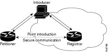
For more information about Secure Device Provisioning, see:
- Contents of Bootstrap Configuration
- Secure Device Provisioning Workflow
- Defining Secure Device Provisioning Policies
Contents of Bootstrap Configuration
The bootstrap configuration provided by SDP typically does the following:
- Sets the petitioner’s hostname.
- Synchronizes the petitioner’s system clock with the registrar.
- Sets the petitioner’s trustpoint.
- Sets the petitioner’s authentication and authorization mechanism.
- Pushes the CA certificate.
- Enrolls the petitioner with the PKI server.
- Sets other VPN configurations, such as the configuration required to establish a management tunnel.
- Sets Cisco Networking Services (CNS) configuration.
- Sets the petitioner’s DHCP pool.
Secure Device Provisioning Workflow
The following illustrates the steps required to use SDP to register a remote-site device in a secure network:
1.![]() Unpack the router and connect the power, LAN, and WAN cables.
Unpack the router and connect the power, LAN, and WAN cables.
2.![]() Turn on a computer (introducer) that is assigned an IP address from the DHCP server on the router, open a web browser, and go to the petitioner URL (http://device/ezsdd/welcome) on the router. The router responds with a registration page (also called the local login dialog box).
Turn on a computer (introducer) that is assigned an IP address from the DHCP server on the router, open a web browser, and go to the petitioner URL (http://device/ezsdd/welcome) on the router. The router responds with a registration page (also called the local login dialog box).
3.![]() Enter the username and password, then click OK. On the welcome page, enter the URL for the registrar. The following actions occur:
Enter the username and password, then click OK. On the welcome page, enter the URL for the registrar. The following actions occur:
a.![]() The browser opens an HTTPS-secured session to the central-site registrar, which verifies the username with the AAA server and returns the appropriate bootstrap configuration to the browser.
The browser opens an HTTPS-secured session to the central-site registrar, which verifies the username with the AAA server and returns the appropriate bootstrap configuration to the browser.
b.![]() The browser feeds the bootstrap configuration to the remote-site router, configuring PKI trustpoint enrollment and IPsec VPN connectivity, and provisioning system attributes and other information.
The browser feeds the bootstrap configuration to the remote-site router, configuring PKI trustpoint enrollment and IPsec VPN connectivity, and provisioning system attributes and other information.
c.![]() You are notified that bootstrap configuration is complete.
You are notified that bootstrap configuration is complete.
Defining Secure Device Provisioning Policies
The petitioner component is automatically enabled on all Cisco IOS routers. The SDP policy in Security Manager enables the registrar. To define an SDP policy you must define:
- The AAA server group containing the AAA server that the registrar uses to authenticate and authorize the introducer.
- The CA server to which the petitioner enrolls during the bootstrap process.
- The location of the introduction page that is displayed after authorization was performed.
- The location of the bootstrap configuration to be provided to the petitioner.
- Secure Device Provisioning Workflow
- Configuring a AAA Server Group for Administrative Introducers
- Secure Device Provisioning on Cisco IOS Routers
Step 1![]() Do one of the following:
Do one of the following:
- (Device view) Select Platform > Device Admin > Secure Device Provisioning from the Policy selector.
- (Policy view) Select Router Platform > Device Admin > Secure Device Provisioning from the Policy Type selector. Select an existing policy or create a new one.
The Secure Device Provisioning page is displayed. See Table 63-37 for a description of the fields on this page.
Step 2![]() Under Introducer Authentication, enter the name of the AAA server group containing the relevant AAA server, or click Select to select it from a list or to create a new object.
Under Introducer Authentication, enter the name of the AAA server group containing the relevant AAA server, or click Select to select it from a list or to create a new object.
The selected AAA server determines whether the username and password supplied by the introducer represent an authorized user. The AAA server must use TACACS+, RADIUS, or be local.
Note![]() Each AAA server in the selected group must be configured to communicate with an interface that exists on the router; otherwise, validation fails. If you want to configure a different AAA server group for authenticating and authorizing administrative introducers, see Configuring a AAA Server Group for Administrative Introducers.
Each AAA server in the selected group must be configured to communicate with an interface that exists on the router; otherwise, validation fails. If you want to configure a different AAA server group for authenticating and authorizing administrative introducers, see Configuring a AAA Server Group for Administrative Introducers.
Step 3![]() Under Petitioner Authentication, define the CA server that authenticates the identity of the petitioner by doing one of the following:
Under Petitioner Authentication, define the CA server that authenticates the identity of the petitioner by doing one of the following:
- Select Local CA Server, then enter the local CA name in the field provided. If you have already configured the CA server locally on the registrar, a trustpoint is generated automatically.
Note If you have not configured the router as the CA server, enter the command Crypto pki server [name] using the CLI or FlexConfigs. This command is mandatory when you deploy an SDP policy configured with a local CA server.
- Select Remote CA Server, then enter the name of a PKI enrollment object, or click Select to select it from a list or to create a new object.
The PKI enrollment object defines the external CA server used in the SDP policy.
Step 4![]() Select the source of the introduction page that is displayed after you log in to the registrar. The introduction page indicates whether authorization was successfully completed and contains a button for completing the process of obtaining the bootstrap configuration.
Select the source of the introduction page that is displayed after you log in to the registrar. The introduction page indicates whether authorization was successfully completed and contains a button for completing the process of obtaining the bootstrap configuration.
If you do not select the default welcome page, you must enter the URL required to access a different welcome page that you prepared elsewhere.
Step 5![]() Select the source of the bootstrap configuration provided to the petitioner to implement its first-time configuration:
Select the source of the bootstrap configuration provided to the petitioner to implement its first-time configuration:
- If the source of the bootstrap configuration is a non-Security Manager URL, enter the URL and also the username and password for accessing the URL, if required.
- If the source of the configuration file is a Security Manager URL:
–![]() Enter the name of a FlexConfig, or click Select to select it from a list or to create a new object. The FlexConfig contains the device commands required to retrieve the appropriate bootstrap configuration. For more information, see Add or Edit FlexConfig Dialog Box.
Enter the name of a FlexConfig, or click Select to select it from a list or to create a new object. The FlexConfig contains the device commands required to retrieve the appropriate bootstrap configuration. For more information, see Add or Edit FlexConfig Dialog Box.
–![]() Enter the device name formula required by the FlexConfig to derive the device name of the petitioner from the username submitted by the introducer. (The two names typically have a fixed relationship.) The default formula is $n, which uses the introducer name to determine the device name.
Enter the device name formula required by the FlexConfig to derive the device name of the petitioner from the username submitted by the introducer. (The two names typically have a fixed relationship.) The default formula is $n, which uses the introducer name to determine the device name.
The device name determines which bootstrap configuration the petitioner should receive. The resulting URL contains the name of the FlexConfig you selected, as well as the parameters and formula you defined.
–![]() Enter a username and password for accessing the Security Manager server containing the FlexConfig. The password can contain alphanumeric characters, but cannot consist of a single digit.
Enter a username and password for accessing the Security Manager server containing the FlexConfig. The password can contain alphanumeric characters, but cannot consist of a single digit.
Configuring a AAA Server Group for Administrative Introducers
Administrative introducers are administrators or management systems that introduce many devices to the PKI network. You can configure a AAA server group for authenticating and authorizing administrative introducers by appending the following FlexConfig to the configuration of the router:
This FlexConfig serves two functions—it configures the AAA server group to use and it associates this server group with the SDP crypto.
For more information about administrative introducers, see Administrative Secure Device Provisioning Introducer on Cisco.com at this URL: http://www.cisco.com/en/US/docs/ios/12_3t/12_3t14/feature/guide/gtadintr.html
Secure Device Provisioning Policy Page
Secure Device Provisioning (SDP) policies (formerly known as Easy Secure Device Deployment or EzSDD) enable you to configure a Cisco IOS router as a registrar. This is the SDP component that retrieves bootstrap configurations for petitioners, which are remote-site devices that are enrolling in the network security infrastructure. These devices uses the bootstrap configuration for first-time configuration purposes. The registrar also verifies the identity of the introducer, which is the user who introduces the petitioner to the registrar.
For more information, see Defining Secure Device Provisioning Policies.
- (Device view) Select Platform > Device Admin > Secure Device Provisioning from the Policy selector.
- (Policy view) Select Router Platform > Device Admin > Secure Device Provisioning from the Policy Type selector. Create a new policy or select an existing one.
- Secure Device Provisioning on Cisco IOS Routers
- Secure Device Provisioning Workflow
- Understanding AAA Server and Server Group Objects
- Understanding FlexConfig Policies and Policy Objects
|
|
|
|---|---|
The AAA server group that authenticates the username and password supplied by the introducer. Enter the name of a AAA server group object, or click Select to select it from a list or to create a new object. Note To configure a separate AAA server group for authenticating administrative introducers, see Configuring a AAA Server Group for Administrative Introducers. |
|
The CA server that authenticates the identity of the petitioner:
Note If you have not configured the router as the CA server, enter the command Crypto pki server [name] using the CLI or FlexConfigs. This command is mandatory when you deploy an SDP policy configured with a local CA server.
|
|
The source of the introduction page to display to the introducer after authorization is performed: |
|
The source of the bootstrap configuration to provide to the petitioner for first-time configuration:
If required, enter a username and password to access the server containing the bootstrap configuration.
– After selecting the FlexConfig, you must enter a username and password to access the Security Manager server that contains the FlexConfig. – Typically a fixed relationship exists between the username and the device name, which enables a formula like this to be established. The default formula is $n, which uses the introducer name to determine the device name. The device name is required to determine the configuration file that the petitioner should receive. If required, enter a username and password to access the server containing the bootstrap configuration. The password can contain alphanumeric characters, but cannot consist of a single digit. |
DHCP on Cisco IOS Routers
In Security Manager, certain security features, such as Easy VPN and 802.1x, require Dynamic Host Configuration Protocol (DHCP) client/server configuration. DHCP is widely used in LAN environments to dynamically assign host IP addresses from a centralized server, which significantly reduces the overhead of administering IP addresses.
DHCP servers assign and manage IP addresses from specified address pools within a router to DHCP clients. If the DHCP server cannot satisfy a DHCP request from its own database, it can forward the request to one or more secondary DHCP servers defined by the network administrator.
Security Manager enables you to configure a Cisco IOS device as a DHCP server for clients (hosts) that are connected to the device’s inside interface. When you configure a DHCP server, you use IP pools (a range of IP addresses reserved for a DHCP server). The IP pools you select determine the range of IP addresses the server can use. These addresses are provided to client devices for a defined period of time called a lease. When this lease expires, the address is returned to the address pool, enabling the DHCP server to assign it to a different device.
For more information about DHCP, see:
- Understanding DHCP Database Agents
- Understanding DHCP Relay Agents
- Understanding DHCP Option 82
- Understanding Secured ARP
To configure a DHCP policy, see:
Understanding DHCP Database Agents
A DHCP database agent is any external host—for example, an FTP, TFTP, or RCP server—that stores the DHCP bindings database. You can include one or more DHCP database agents in each DHCP policy, as well as configure the interval between database updates to the agent.
Note![]() If you configure an external DHCP database agent, it is not necessary to define IP address pools, but you may do so. For more information about IP address pools, see Defining DHCP Address Pools.
If you configure an external DHCP database agent, it is not necessary to define IP address pools, but you may do so. For more information about IP address pools, see Defining DHCP Address Pools.
Understanding DHCP Relay Agents
A DHCP relay agent is any host that forwards DHCP packets between clients and servers when they do not reside on the same physical subnet. Relay agents receive DHCP messages and then generate a new DHCP message to send on another interface. You can configure a reforwarding policy that determines what the DHCP relay agent should do if a forwarded message already contains relay information.
DHCP relay options in Security Manager include:
- Drop—The relay agent discards messages with existing relay information if Option 82 information is also present.
- Keep—The relay agent retains existing relay information.
- Replace—The relay agent overwrites existing information with its own relay information.
For example, you can have the DHCP relay agent replace the forwarded message with a new relay message. Additionally, you can choose whether to have the relay agent check the validity of relay information contained within forwarded BOOTREPLY messages.
Understanding DHCP Option 82
DHCP option 82 enables the DHCP relay agent to include information about itself and its attached client when it forwards requests from a DHCP client to a DHCP server. The DHCP server can use this information to assign IP addresses, perform access control, and set quality of service (QoS) and security policies for each of its subscribers. When the DHCP option 82 feature is enabled, a subscriber is identified by the switch port through which it connects to the networks, instead of by its MAC address. Multiple hosts on the subscriber LAN can be connected to the same port on the access switch and are uniquely identified. Option 82 also enhances security on access switches by providing the ability to use a user’s IP address to locate the port on which a user is attached.
Understanding Secured ARP
The DHCP Secure IP Address Assignment feature (also called DHCP Authorized ARP) enables you to secure Address Resolution Protocol (ARP) table entries to DHCP leases in the DHCP database. This feature secures and synchronizes the client’s MAC address to the DHCP binding, preventing unauthorized clients or hackers from spoofing the DHCP server and taking over a DHCP lease of an authorized client.
When you enable this feature and the DHCP server assigns an IP address to the DHCP client, the DHCP server adds a secure ARP entry to the ARP table with the assigned IP address and the MAC address of the client. These ARP entries cannot be updated by any other dynamic ARP packets, and they exist in the ARP table for as long as the lease is active.
Secure ARP entries can be deleted only by an explicit termination message from the DHCP client or by the DHCP server when the binding expires. To detect when a client has logged out, Secured ARP sends periodic ARP messages to which only authorized users can respond. Unauthorized responses are blocked at the DHCP server, providing an additional level of security.
Note![]() Secured ARP disables dynamic ARP learning on an interface.
Secured ARP disables dynamic ARP learning on an interface.
Defining DHCP Policies
When you configure a DHCP policy, you must define the IP address pools for the server to use to provide addresses to DHCP clients. In addition, you can optionally define the following:
Note![]() When configuring DHCP on a Cisco IOS router, make sure that the router does not contain an access rule denying Bootstrap Protocol (BootP) traffic. Having such a rule blocks DHCP traffic from being transmitted.
When configuring DHCP on a Cisco IOS router, make sure that the router does not contain an access rule denying Bootstrap Protocol (BootP) traffic. Having such a rule blocks DHCP traffic from being transmitted.
Step 1![]() Do one of the following:
Do one of the following:
- (Device view) Select Platform > Device Admin > Server Access > DHCP from the Policy selector.
- (Policy view) Select Router Platform > Device Admin > Server Access > DHCP from the Policy Type selector. Select an existing policy or create a new one.
The DHCP Policy page is displayed. See Table 63-38 for a description of the fields on this page.
Step 2![]() (Optional) Under Databases, click the Add button to display the DHCP Database Dialog Box. From here you can define external DHCP database agents. For more information, see Understanding DHCP Database Agents.
(Optional) Under Databases, click the Add button to display the DHCP Database Dialog Box. From here you can define external DHCP database agents. For more information, see Understanding DHCP Database Agents.
Step 3![]() (Optional) Under Excluded IPs, enter the IP addresses or address ranges within a DHCP address pool that should not be made available to DHCP clients. You can use a combination of addresses and network/host objects, or click Select to display a selector. For more information, see Specifying IP Addresses During Policy Definition.
(Optional) Under Excluded IPs, enter the IP addresses or address ranges within a DHCP address pool that should not be made available to DHCP clients. You can use a combination of addresses and network/host objects, or click Select to display a selector. For more information, see Specifying IP Addresses During Policy Definition.
Tip If the network you want is not listed in the selector, click the Create button to display the Add or Edit Network/Host Dialog Box. From here you can create a network/host object.
Step 4![]() Under IP Pools, click the Add button to display the IP Pool Dialog Box. From here you can define the address pools to be used by the DHCP server. For more information, see Defining DHCP Address Pools.
Under IP Pools, click the Add button to display the IP Pool Dialog Box. From here you can define the address pools to be used by the DHCP server. For more information, see Defining DHCP Address Pools.
Step 5![]() (Optional) When you use a relay agent to manage requests from DHCP clients located on a different subnet from the DHCP server, define the following DHCP relay options:
(Optional) When you use a relay agent to manage requests from DHCP clients located on a different subnet from the DHCP server, define the following DHCP relay options:
a.![]() Select the relay agent information reforwarding policy (Drop, Keep, or Replace). DHCP relay agents implement this policy when they receive messages already containing relay information.
Select the relay agent information reforwarding policy (Drop, Keep, or Replace). DHCP relay agents implement this policy when they receive messages already containing relay information.
b.![]() Select the Option check box to enable the insertion of Option 82 data in requests that the relay agent forwards to the DHCP server.
Select the Option check box to enable the insertion of Option 82 data in requests that the relay agent forwards to the DHCP server.
c.![]() Select the Check check box to validate DHCP Option 82 reply packets sent by the DHCP server.
Select the Check check box to validate DHCP Option 82 reply packets sent by the DHCP server.
When you enable this option, invalid messages are dropped. Valid messages are stripped of the option-82 field before they are forwarded to the DHCP client. When you disable this option, the option-82 field is removed from the packet without being checked first for validity.
See Understanding DHCP Relay Agents for more information.
Defining DHCP Address Pools
When you configure a DHCP policy that does not include an external database agent, you must define at least one IP address pool. This pool contains the addresses that the DHCP server can dynamically assign to DHCP clients. Additionally, you can define the following IP pool-specific options:
- The default routers, DNS servers, WINS servers, and domain used by DHCP clients.
- Whether to use the Secured ARP feature.
- Whether to import information regarding IP pool options from a centralized DHCP server.
- The length of the lease.
- The location of the TFTP server that IP telephony devices require to use addresses from this pool.
Step 1![]() On the DHCP page, click the Create button under IP Pools. The IP Pool dialog box is displayed.
On the DHCP page, click the Create button under IP Pools. The IP Pool dialog box is displayed.
Step 2![]() Define the address pool. See Table 63-40 for a description of the available fields.
Define the address pool. See Table 63-40 for a description of the available fields.
Step 3![]() Click OK to save your definitions locally on the client and close the dialog box. The IP pool appears in the table displayed under IP Pools on the DHCP page.
Click OK to save your definitions locally on the client and close the dialog box. The IP pool appears in the table displayed under IP Pools on the DHCP page.
Step 4![]() Repeat Step 1 through Step 3 to define additional address pools, if required.
Repeat Step 1 through Step 3 to define additional address pools, if required.
Note![]() To edit an IP pool, select it from the table, then click the Edit button. To delete an IP pool, select it from the table, then click the Delete button. You cannot delete a pool whose addresses have been assigned to DHCP clients.
To edit an IP pool, select it from the table, then click the Edit button. To delete an IP pool, select it from the table, then click the Delete button. You cannot delete a pool whose addresses have been assigned to DHCP clients.
DHCP Policy Page
Use the DHCP policy page to define a DHCP server policy on the selected router. This includes specifying the address pools used by the DHCP server when assigning addresses to requesting clients.
For more information, see Defining DHCP Policies.
- (Device view) Select Platform > Device Admin > Server Access > DHCP from the Policy selector.
- (Policy view) Select Router Platform > Device Admin > Server Access > DHCP from the Policy Type selector. Right-click DHCP to create a policy, or select an existing policy from the Shared Policy selector.
|
|
|
|---|---|
The amount of time to wait (in seconds) for a response from the external DHCP database agent before aborting a database transfer. |
|
The interval (in seconds) between DHCP assignment updates sent to the external DHCP database agent. |
|
Opens the DHCP Database Dialog Box. From here you can define a DHCP database agent. |
|
Opens the DHCP Database Dialog Box. From here you can edit the selected DHCP database agent. |
|
The IP addresses or address ranges to exclude from DHCP. These addresses are not assigned by the DHCP server to DHCP clients requesting addresses. Enter one or more network addresses or network/host objects, or click Select to select an object from a list or to create a new object. For more information, see Specifying IP Addresses During Policy Definition. |
|
The IP addresses of the default routers used by DHCP clients. |
|
The IP addresses of the Windows Internet Naming Service (WINS) servers used by Microsoft DHCP clients. |
|
Indicates whether the remote DHCP server imports certain DHCP options from a centralized DHCP server. |
|
Indicates whether secured ARP is enabled on this IP pool to help prevent IP spoofing by unauthorized users. |
|
The duration of the lease for each IP address assigned by the DHCP server from this IP pool. |
|
The IP address of the TFTP server required by IP phones for configuration, as defined using DHCP option 150. |
|
The IP address of the TFTP server required by IP phones for configuration, as defined using DHCP option 66. |
|
Opens the IP Pool Dialog Box. From here you can define a DHCP IP address pool. |
|
Opens the IP Pool Dialog Box. From here you can edit the selected IP pool. |
|
The policy that DHCP relay agents implement when they receive messages already containing relay information: |
|
When selected, enables DHCP Option 82 data insertion in message requests forwarded from the DHCP client to the server. DHCP Option 82 provides the DHCP server with both the switch and port ID of the requesting client. This option makes it possible to locate where a user is physically connected to the network and prevent spoofing. See Understanding DHCP Option 82. |
|
When selected, DHCP Option 82 reply packets received from the DHCP server are validated. Invalid messages are dropped; valid messages are stripped of the option-82 field before being forwarded to the DHCP client. When deselected, the option-82 field is removed from the packet without being checked first for validity. |
|
DHCP Database Dialog Box
Use the DHCP Database dialog box to define external DHCP database agents that contain the automatic bindings. Each database URL that you define must be unique.
For more information, see Understanding DHCP Database Agents.
Go to the DHCP Policy Page, then click the Add or Edit button beneath the Databases table.
IP Pool Dialog Box
Use the IP Pool dialog box to define one or more address pools, which the DHCP server uses to assign dynamic addresses to DHCP clients. You must define at least one address pool, unless you have defined an external DHCP database agent.
Go to the DHCP Policy Page, then click the Add or Edit button beneath the IP Pools table.
- Defining DHCP Address Pools
- Understanding DHCP Database Agents
- DHCP Database Dialog Box
- DHCP on Cisco IOS Routers
|
|
|
|---|---|
The IP address and subnet mask of the IP pool. This subnet contains the range of available IP addresses that the DHCP server may assign to clients. Enter an address and mask or the name of a network/host object, or click Select to select an object from a list or to create a new one. |
|
The IP addresses of the default routers for DHCP clients using this IP pool. After a DHCP client is booted, it begins sending packets to this router, which should be located on the same subnet as the client. Enter up to eight (8) network addresses or network/host objects, or click Select to select an object from a list or to create a new one. |
|
The IP addresses of the DNS servers that DHCP clients using this IP pool should query when they need to correlate hostnames to IP addresses. Enter up to eight (8) network addresses or network/host objects, or click Select to select an object from a list or to create a new one. |
|
The IP addresses of the Windows Internet Naming Service (WINS) servers used by Microsoft DHCP clients to correlate hostnames to IP addresses within a general grouping of networks. Enter up to eight (8) network addresses or network/host objects, or click Select to select an object from a list or to create a new one. |
|
The domain name for DHCP clients using this IP pool. This name places these clients in the general grouping of networks that make up the domain. |
|
When selected, enables remote DHCP servers to import specific DHCP options (such as the DNS server) from a centralized server. Use this option to enable configuration information to be updated automatically. When deselected, all DHCP options are local to this specific server. |
|
When selected, enables the DHCP Authorized ARP feature, which limits the leasing of IP addresses to authorized mobile users. This feature helps prevent IP spoofing by unauthorized users. See Understanding Secured ARP. When deselected, the DHCP Authorized ARP feature is disabled. Note This feature also disables dynamic ARP learning on an interface. |
|
When selected, the DHCP server permanently assigns IP addresses to its clients. When deselected, addresses are leased for a predefined amount of time, as defined in the Time Length field. |
|
Applies only when the Lease Never Expires check box is deselected. The duration of the lease provided to each IP address assigned from this IP pool (using the format DD:HH:MM). After the lease expires, the assigned IP address is no longer valid and is returned to the pool. |
|
The IP address of the TFTP server used to provide configuration files to IP phones. These configuration files define parameters required by IP phones to connect to Cisco CallManager. Enter up to eight (8) network addresses or network/host objects, or click Select to select an object from a list or to create a new one. Note This option is functionally similar to option 150. Either or both options may be used. |
|
The IP address of the TFTP server used to provide configuration files to IP phones. These configuration files define parameters required by IP phones to connect to Cisco CallManager. Enter up to eight (8) network addresses or network/host objects, or click Select to select an object from a list or to create a new one. Note This option is functionally similar to option 66. Either or both options may be used. |
NTP on Cisco IOS Routers
The Network Time Protocol (NTP) is the standard for time synchronization between network devices. Synchronized time enables you to correlate syslog and other debug output to specific events, which is essential for troubleshooting, fault analysis, and security incident tracking. Time comparisons are not possible without precise time synchronization between the logging, management, and AAA functions occurring in your network.
NTP uses the concept of a stratum to describe how far removed a machine is from an authoritative time source. For example, a stratum 1 time server is directly attached to a radio or atomic clock. NTP then distributes the time from this authoritative time source across the network. A stratum 2 time server synchronizes with a stratum 1 time server; a stratum 3 time server synchronizes with a stratum 2 time server and so on. One NTP transaction per minute is sufficient to synchronize two machines to within a millisecond.
NTP runs over the User Datagram Protocol (UDP) using port 123. Security Manager supports NTP version 3, as defined in RFC 1305.
Defining NTP Servers
This procedure describes how to define the NTP servers that the routers users to synchronize time. After the NTP policy is deployed, the router uses an algorithm (based on factors such as delay, dispersion, and jitter) to determine which NTP server is the most accurate and synchronizes to that one.
At the global level, you can enable MD5 authentication and specify a source address to use on all NTP packets sent from the router.
To add an NTP server to the policy, all you need to do is enter its IP address. In addition, you can optionally define authentication parameters and determine whether a particular server should be preferred over other NTP servers of similar accuracy.
Step 1![]() Do one of the following:
Do one of the following:
- (Device view) Select Platform > Device Admin > Server Access > NTP from the Policy selector.
- (Policy view) Select Router Platform > Device Admin > Server Access > NTP from the Policy Type selector. Select an existing policy or create a new one.
The NTP page is displayed. See Table 63-41 for a description of the fields on this page.
Step 2![]() (Optional) In the Source Interface field, enter the name of the interface or interface role whose address should be used as the source interface for all NTP packets sent from the router, or click Select to select an interface role from a list or to create a new one. The source interface must have an IP address.
(Optional) In the Source Interface field, enter the name of the interface or interface role whose address should be used as the source interface for all NTP packets sent from the router, or click Select to select an interface role from a list or to create a new one. The source interface must have an IP address.
This option is useful when the NTP server cannot reach the address from which the connection originated (for example, due to a firewall). If you do not enter a value in this field, the address of the outgoing interface is used.
Note![]() You can override this global setting for individual NTP servers, as described in Step 5.
You can override this global setting for individual NTP servers, as described in Step 5.
Step 3![]() (Optional) Select the Enable NTP Authentication check box to authenticate all associations between this router and the NTP servers defined in this policy.
(Optional) Select the Enable NTP Authentication check box to authenticate all associations between this router and the NTP servers defined in this policy.
Step 4![]() Click the Add button under the Servers table to display the NTP Server dialog box. From here you can define an NTP server.
Click the Add button under the Servers table to display the NTP Server dialog box. From here you can define an NTP server.
Step 5![]() Define an NTP server. See Table 63-42 for a description of the available fields.
Define an NTP server. See Table 63-42 for a description of the available fields.
Step 6![]() (Optional) Define authentication parameters for this NTP server.
(Optional) Define authentication parameters for this NTP server.
Note![]() If you modify the value of a previously defined authentication key, the change affects all NTP servers that share this key.
If you modify the value of a previously defined authentication key, the change affects all NTP servers that share this key.
Note![]() When you define an authentication key in Security Manager, the value 0 is automatically appended to the end of the CLI command. This value, which represents the default authentication key encryption type, can be modified using the CLI.
When you define an authentication key in Security Manager, the value 0 is automatically appended to the end of the CLI command. This value, which represents the default authentication key encryption type, can be modified using the CLI.
Step 7![]() Repeat Step 5 and Step 6 to define additional NTP servers.
Repeat Step 5 and Step 6 to define additional NTP servers.
Step 8![]() Click OK to save your definitions locally on the client and close the dialog box. Your definitions are displayed in the Servers table.
Click OK to save your definitions locally on the client and close the dialog box. Your definitions are displayed in the Servers table.
Note![]() To edit an NTP server, select it from the Servers table, then click Edit. To remove an NTP server, select it, then click Delete. If the key defined on the server you delete is not defined on a different NTP server, the key is also deleted.
To edit an NTP server, select it from the Servers table, then click Edit. To remove an NTP server, select it, then click Delete. If the key defined on the server you delete is not defined on a different NTP server, the key is also deleted.
NTP Policy Page
Use the NTP page to define one or more NTP servers that the router can use for time synchronization. This includes enabling authentication, if required, and defining a global source interface for all traffic sent to these servers.
For more information, see Defining NTP Servers.
- (Device view) Select Platform > Device Admin > Server Access > NTP from the Policy selector.
- (Policy view) Select Router Platform > Device Admin > Server Access > NTP from the Policy Type selector. Right-click NTP to create a policy, or select an existing policy from the Shared Policy selector.
- NTP on Cisco IOS Routers
- Understanding Interface Role Objects
- Table Columns and Column Heading Features
- Filtering Tables
|
|
|
|---|---|
The source address for all packets sent to an NTP server. This setting might be necessary when the NTP server cannot respond to the address from which the packet originated (for example, due to a firewall). The source interface must have an IP address. If you do not define a value in this field, the address of the outgoing interface is used. Enter the name of an interface or interface role, or click Select to select the object from a list or to create a new one. Note The source interface defined in this field is a global setting that you can override for individual NTP servers. For more information, see NTP Server Dialog Box. |
|
When selected, enables authentication using MD5 when connecting to an NTP server. |
|
The source address for all packets sent to this NTP server. This setting overrides the global setting defined at the top of the page. |
|
Indicates whether this NTP server is preferred over other NTP servers of similar accuracy. Note By default, preferred servers are listed first in the table. |
|
The ID number of the key used for authentication with this NTP server. |
|
Indicates whether the authentication key defined for this NTP server is a trusted key. |
|
Opens the NTP Server Dialog Box. From here you can define an NTP server. |
|
Opens the NTP Server Dialog Box. From here you can edit the selected NTP server. |
|
Deletes the selected NTP server from the table. If the key defined on the server you delete is not defined on a different NTP server, the key is also deleted. |
|
NTP Server Dialog Box
Use the NTP Server dialog box to define the address of an NTP server that the router can use to perform time synchronization. In addition, you can use this dialog box to define a default source interface for NTP packets sent to this server and authentication parameters.
Go to the NTP Policy Page, then click the Add or Edit button beneath the table.
|
|
|
|---|---|
The IP address of the NTP server. Enter an address or the name of a network/host object, or click Select to select the object from a list or to create a new one. |
|
The source address for all packets sent to this NTP server. This setting might be necessary when the NTP server cannot respond to the address from which the packet originated (for example, due to a firewall). The source interface must have an IP address. If you do not define a value in this field and there is no global setting, the address of the outgoing interface is used. Note This setting overrides the global setting you defined on the NTP Policy Page. Enter the name of an interface or interface role, or click Select to select the object from a list or to create a new one. |
|
When selected, this NTP server is preferred over other NTP servers of similar accuracy. If this server is used for synchronization, the time offset used to correct the local clock is calculated from this server only. Note If a different NTP server is significantly more accurate than the preferred server (for example, stratum 2 versus stratum 3), the router synchronizes to the more accurate server. When deselected, this NTP server is not given preference over other NTP servers of similar accuracy. The time offset used to correct the local clock is calculated by taking the combined offset of all NTP servers. We recommend that you configure an NTP server as preferred only when multiple servers have the same stratum and you can rely on the accuracy of the preferred server. |
|
The MD5 key that is used to authenticate associations with the NTP server.
If you select a key number from the list and then change the key value, you are warned that saving this change affects any other NTP servers using the same authentication key. Note To use authentication, you must enable it from the NTP Policy Page. |
 Feedback