Camera Installation
This chapter provides information and instructions for installing the Cisco Video Surveillance 7070 IP Camera.
The IP camera requires a network cable and a connection to a standard 10/100BaseT router or switch. To power the IP camera with Power over Ethernet (PoE), a switch must be 802.3af or 802.3at compliant.
Warnings

Warning![]() Power off the IP camera if smoke or unusual odors are detected.
Power off the IP camera if smoke or unusual odors are detected.
Warning![]() Do not place the IP camera on unsteady surfaces.
Do not place the IP camera on unsteady surfaces.
Warning![]() Do not put sharp or tiny objects into the IP camera.
Do not put sharp or tiny objects into the IP camera.
Warning![]() See the data sheet for operating temperatures.
See the data sheet for operating temperatures.
Warning![]() Do not touch the IP camera during a lightning storm.
Do not touch the IP camera during a lightning storm.
Warning![]() Do not drop the IP camera.
Do not drop the IP camera.
Warning![]() Installation of the equipment must comply with local and national electrical codes. Statement 1074
Installation of the equipment must comply with local and national electrical codes. Statement 1074
Warning![]() This product must be connected to a power-over-ethernet (PoE) IEEE 802.3af compliant power source or an IEC60950 compliant limited power source. Statement 353
This product must be connected to a power-over-ethernet (PoE) IEEE 802.3af compliant power source or an IEC60950 compliant limited power source. Statement 353
Warning![]() Due to its high performance IR lights, the surface temperature of the dome cover can reach 158ºF (70ºC) after operating in night mode for a period of time. You should wait for the surface to cool down if you need to re-install the camera.
Due to its high performance IR lights, the surface temperature of the dome cover can reach 158ºF (70ºC) after operating in night mode for a period of time. You should wait for the surface to cool down if you need to re-install the camera.

Note![]() This equipment is only to be connected to PoE networks without routing to outside plants.
This equipment is only to be connected to PoE networks without routing to outside plants.
For PoE input connection, use only UL listed I.T.E. with PoE output.
Mounting Positions
The following figures show the mounting positions for the IP camera:
- Figure 2-1—Camera base plate mounting positions
- Figure 2-2—Camera mounting plate mounting positions
Figure 2-1 Camera Base Plate Mounting Positions
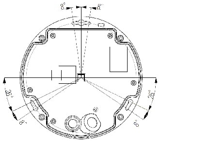
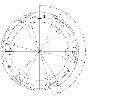
Figure 2-2 Camera Mounting Plate Mounting Positions
Installing the IP Camera
This section describes how to install the IP camera on a ceiling, wall, or table.
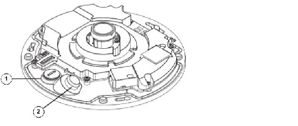
(Optional) Insert a MicroSD card, if needed. See Figure 1-1.
To install the IP camera, follow these steps:
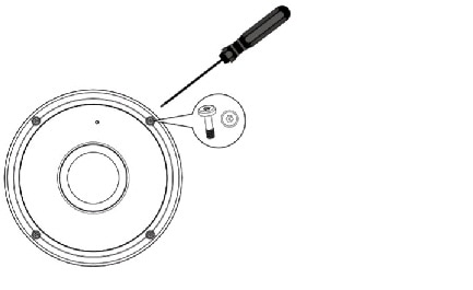
Step 1![]() Use the provided T10 screwdriver for tamper-proof screws to detach the dome cover from the camera base as shown in Figure 2-3.
Use the provided T10 screwdriver for tamper-proof screws to detach the dome cover from the camera base as shown in Figure 2-3.
Figure 2-3 Detaching the Dome Cover from the IP Camera
a.![]() Remove the rubber seal for the Ethernet cable as shown in Figure 2-4.
Remove the rubber seal for the Ethernet cable as shown in Figure 2-4.
b.![]() (Optional) If you will use DC power or an external microphone or speaker, remove the rubber stopper for the power and IO cable as shown in Figure 2-4.
(Optional) If you will use DC power or an external microphone or speaker, remove the rubber stopper for the power and IO cable as shown in Figure 2-4.
Figure 2-4 Removing Stopper and Seal Plug for Cables
|
|
|
|
|
Step 3![]() If you want to feed cables through the bottom of the IP camera, take the following actions to mount the camera to a ceiling, wall, or table without a mounting plate.
If you want to feed cables through the bottom of the IP camera, take the following actions to mount the camera to a ceiling, wall, or table without a mounting plate.
If you want to feed cables through the side of the IP camera, go to Step 4.
a.![]() Attach the provided alignment sticker for the camera base to location on the ceiling, wall, or table at which you want to mount the camera.
Attach the provided alignment sticker for the camera base to location on the ceiling, wall, or table at which you want to mount the camera.
If you are mounting the camera on a wall, make sure that the alignment sticker is oriented so that the “Alignment Sticker” text is right side up and horizontally level.
b.![]() Using the three drill hole marks on the alignment sticker, drill three pilot holes into the ceiling, wall, or table, then put the provided wall plugs into the holes.
Using the three drill hole marks on the alignment sticker, drill three pilot holes into the ceiling, wall, or table, then put the provided wall plugs into the holes.
Use a hammer to drive the anchors into the holes.
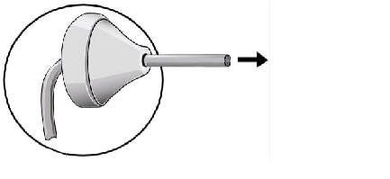
c.![]() Poke a hole in the provided rubber seal plug and feed the RJ45 24AWG Ethernet cable through the hole, as shown in Figure 2-5.
Poke a hole in the provided rubber seal plug and feed the RJ45 24AWG Ethernet cable through the hole, as shown in Figure 2-5.
Figure 2-5 Inserting the Ethernet Cable through the Rubber Seal Plug
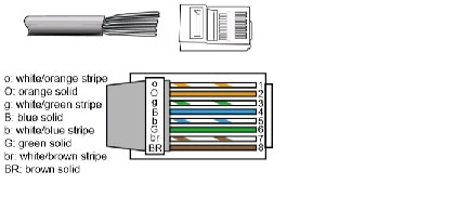
d.![]() Strip 1/2 inch (12.7 mm) of the sheath from the end of the Ethernet cable that will attach to the IP camera and use an RJ45 crimping tool to attach an RJ45 connector to the cable
Strip 1/2 inch (12.7 mm) of the sheath from the end of the Ethernet cable that will attach to the IP camera and use an RJ45 crimping tool to attach an RJ45 connector to the cable
The cable wires must be aligned in the connector as shown in Figure 2-6.
Figure 2-6 Attaching an RJ45 Connector
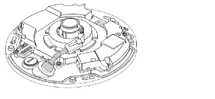
e.![]() Feed the Ethernet cable through its hole at the bottom of the IP camera base and attach the rubber seal plug from the bottom of the camera for water proofing as shown in Figure 2-7.
Feed the Ethernet cable through its hole at the bottom of the IP camera base and attach the rubber seal plug from the bottom of the camera for water proofing as shown in Figure 2-7.
Figure 2-7 Feeding the Ethernet Cable through the IP Camera
f.![]() Connect the Ethernet cable to the 10/100BaseT RJ45 socket on the IP camera (see Figure 1-1).
Connect the Ethernet cable to the 10/100BaseT RJ45 socket on the IP camera (see Figure 1-1).
g.![]() If you will power the IP camera with DC power or use an external speaker or microphone:
If you will power the IP camera with DC power or use an external speaker or microphone:
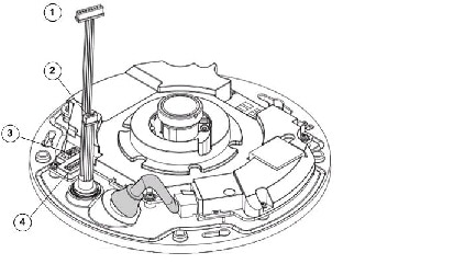
–![]() Attach the provided rubber washer to the provided power and IO cable, feed the cable through its hole in the bottom of the IP camera base, and screw the plastic base of the cable into the camera for water proofing, as shown in Figure 2-8.
Attach the provided rubber washer to the provided power and IO cable, feed the cable through its hole in the bottom of the IP camera base, and screw the plastic base of the cable into the camera for water proofing, as shown in Figure 2-8.
–![]() To power the IP camera with DC power, connect the DC power connector to the DC power J6 socket on the IP camera, as shown in Figure 2-8.
To power the IP camera with DC power, connect the DC power connector to the DC power J6 socket on the IP camera, as shown in Figure 2-8.
–![]() To use an external speaker or microphone, connect the IO connector to the IO J7 socket on the IP camera, as shown in Figure 2-8.
To use an external speaker or microphone, connect the IO connector to the IO J7 socket on the IP camera, as shown in Figure 2-8.
When you connect a DC power cable, external speaker, or external microphone to the IP camera, connect the power to the black jack, connect the speaker to the green jack, and connect the microphone to the pink jack on the power and IO cable.
Figure 2-8 Connecting the Power and IO Cable
|
|
|
|
|
|
|
|
|
|
|
h.![]() Attach the camera base to the ceiling, wall, or table by using the three provided M3 x 25 screws.
Attach the camera base to the ceiling, wall, or table by using the three provided M3 x 25 screws.
i.![]() Replace the desiccant bag that is in the camera with the desiccant bag that is provided with the camera accessories.
Replace the desiccant bag that is in the camera with the desiccant bag that is provided with the camera accessories.
j.![]() Reattach the dome cover to the camera base by using the provided screwdriver for tamper-proof screws to fasten three screws tamper-proof screws.
Reattach the dome cover to the camera base by using the provided screwdriver for tamper-proof screws to fasten three screws tamper-proof screws.
Skip to Step 5.
Step 4![]() If you want to feed cables through the side of the IP camera, take the following actions to mount the camera to a ceiling, wall, or table with a mounting plate:
If you want to feed cables through the side of the IP camera, take the following actions to mount the camera to a ceiling, wall, or table with a mounting plate:
a.![]() Attach the provided alignment sticker for the mounting plate to location on the ceiling, wall, or table at which you want to mount the camera.
Attach the provided alignment sticker for the mounting plate to location on the ceiling, wall, or table at which you want to mount the camera.
If you are mounting the camera on a wall, make sure that the alignment sticker is oriented so that the “Alignment Sticker” text is right side up and horizontally level.
b.![]() Using the three drill hole marks on the alignment sticker, drill three pilot holes into the ceiling, wall, or table, then put the included screw anchors into the holes.
Using the three drill hole marks on the alignment sticker, drill three pilot holes into the ceiling, wall, or table, then put the included screw anchors into the holes.
Use a hammer to drive the anchors into the holes, if needed.
c.![]() Feed the Ethernet cable and, if needed, the provided power and IO cable through the side of the mounting plate.
Feed the Ethernet cable and, if needed, the provided power and IO cable through the side of the mounting plate.
d.![]() Attach the mounting plate to the ceiling, wall, or table by using the three provided M3 x 25 screws.
Attach the mounting plate to the ceiling, wall, or table by using the three provided M3 x 25 screws.
e.![]() Poke a hole in the provided rubber seal plug and feed the RJ45 24AWG Ethernet cable through the hole, as shown in Figure 2-9.
Poke a hole in the provided rubber seal plug and feed the RJ45 24AWG Ethernet cable through the hole, as shown in Figure 2-9.
Figure 2-9 Inserting the Ethernet Cable through the Rubber Seal Plug

f.![]() Strip 1/2 inch (12.7 mm) of the sheath from the end of the Ethernet cable that will attach to the IP camera and use an RJ45 crimping tool to attach an RJ45 connector to the cable
Strip 1/2 inch (12.7 mm) of the sheath from the end of the Ethernet cable that will attach to the IP camera and use an RJ45 crimping tool to attach an RJ45 connector to the cable
The cable wires must be aligned in the connector as shown in Figure 2-10.
Figure 2-10 Attaching an RJ45 Connector

g.![]() Feed the Ethernet cable through its hole at the bottom of the IP camera base and attach the rubber seal plug from the bottom of the camera for water proofing as shown in Figure 2-11.
Feed the Ethernet cable through its hole at the bottom of the IP camera base and attach the rubber seal plug from the bottom of the camera for water proofing as shown in Figure 2-11.
Figure 2-11 Feeding the Ethernet Cable through the IP Camera

h.![]() Connect the Ethernet cable to the 10/100BaseT RJ45 socket on the IP camera (see Figure 1-1).
Connect the Ethernet cable to the 10/100BaseT RJ45 socket on the IP camera (see Figure 1-1).
i.![]() If you will power the IP camera with DC power or use an external speaker or microphone:
If you will power the IP camera with DC power or use an external speaker or microphone:
–![]() Attach the provided rubber washer to the provided power and IO cable, feed the cable through its hole in the bottom of the IP camera base, and screw the plastic base of the cable into the camera for water proofing.
Attach the provided rubber washer to the provided power and IO cable, feed the cable through its hole in the bottom of the IP camera base, and screw the plastic base of the cable into the camera for water proofing.
–![]() To power the IP camera with DC power, connect the DC power connector to the DC power J6 socket on the IP camera, as shown in Figure 2-12.
To power the IP camera with DC power, connect the DC power connector to the DC power J6 socket on the IP camera, as shown in Figure 2-12.
–![]() To use an external speaker or microphone, connect the IO connector to the IO J7 socket on the IP camera, as shown in Figure 2-12.
To use an external speaker or microphone, connect the IO connector to the IO J7 socket on the IP camera, as shown in Figure 2-12.
When you connect a DC power cable, external speaker, or external microphone to the IP camera, connect the power to the black jack, connect the speaker to the green jack, and connect the microphone to the pink jack on the power and IO cable.
Figure 2-12 Connecting the Power and IO Cable

|
|
|
|
|
|
|
|
|
|
|
j.![]() Attach the camera base to the mounting plate and turn counter-clockwise, then secure the mounting plate by using the provided screws.
Attach the camera base to the mounting plate and turn counter-clockwise, then secure the mounting plate by using the provided screws.
k.![]() Replace the desiccant bag that is in the camera with the desiccant bag that is provided with the camera accessories.
Replace the desiccant bag that is in the camera with the desiccant bag that is provided with the camera accessories.
l.![]() Secure the dome cover to the camera base by using the provided screwdriver for tamper-proof screws to fasten three screws tamper-proof screws.
Secure the dome cover to the camera base by using the provided screwdriver for tamper-proof screws to fasten three screws tamper-proof screws.
Step 5![]() Use one of the following methods to connect the IP camera to power.
Use one of the following methods to connect the IP camera to power.
- To connect the IP camera if you are powering it with PoE through a PoE-enabled switch, connect the IP camera to the switch.
- To connect the IP camera if you are powering it with PoE through a non-PoE switch, connect the IP camera to the switch through a PoE power injector as shown in the following figure.
- After you install the IP camera, follow the instructions in Chapter 3, “Performing the Initial Setup of the IP Camera” to access the IP camera through your network.
- After completing the initial setup, access the Camera Video and Control window from the IP camera web-based interface, choose Camera Settings > Advanced Settings, and from the Mount Type drop-down list, choose the surface type on which you installed the IP camera. For more information, see the “Viewing Live Video” section.
 Feedback