|
Chassis
|
One rack-unit (1RU) chassis
|
|
Central Processor
|
Up to two 3rd Generation Intel Xeon processors
|
|
Memory
|
32 slots for registered DIMMs (RDIMMs), DDR4 DIMMs, 3DS DIMMs, and load-reduced DIMMs (LR DIMMs) up to 3200 MHz. Also supports
Intel Optane Persistent Memory Modules (PMEMs)
|
|
Multi-bit error protection
|
Supports multi-bit error protection
|
|
Video
|
The Cisco Integrated Management Controller (Cisco IMC) provides video using the Matrox G200e video or graphics controller:
-
Integrated 2D graphics core with hardware acceleration
-
DDR3 memory interface supports up to 512 MB of addressable memory (8 MB is allocated by default to video memory)
-
Supports display resolutions up to 1920 x 1200 16bpp at 60Hz
-
High-speed integrated 24-bit RAMDAC
-
Single-lane PCI-Express host interface running at Gen 2 speed
|
|
Baseboard management
|
BMC, running Cisco IMC firmware.
Depending on your Cisco IMC settings, Cisco IMC can be accessed through the 1-Gb dedicated management port, the 1-Gb/10-Gb
Ethernet LAN ports, or a Cisco virtual interface card.
|
|
Network and management I/O
|
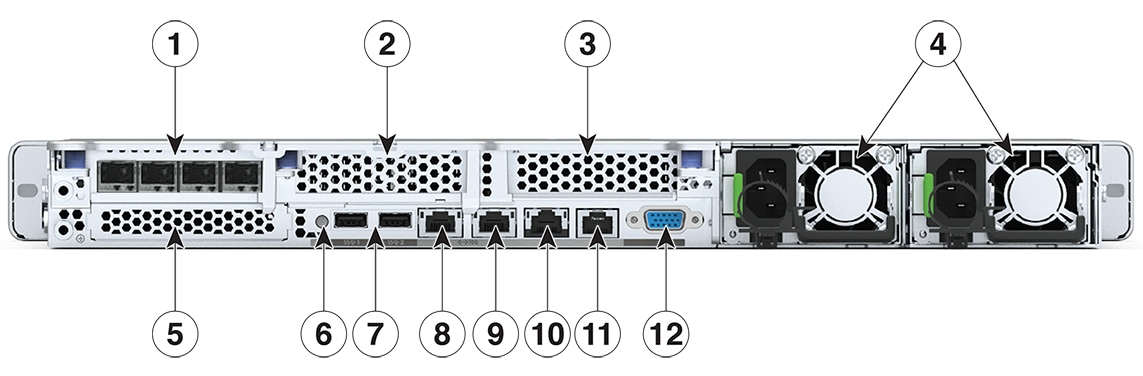
Rear panel:
-
One 1-Gb Ethernet dedicated management port (RJ-45 connector)
-
Two 1-Gb or 10-Gb BASE-T Ethernet LAN ports (RJ-45 connectors)
The dual LAN ports can support 10 Gbps, 1 Gbps, 100 Mbps, or 10 Mbps. The LAN ports autonegotiate to the correct link speed
based on the link partner capability.
-
One RS-232 serial port (RJ-45 connector)
-
One VGA video connector port (DB-15 connector)
-
Two USB 3.0 ports
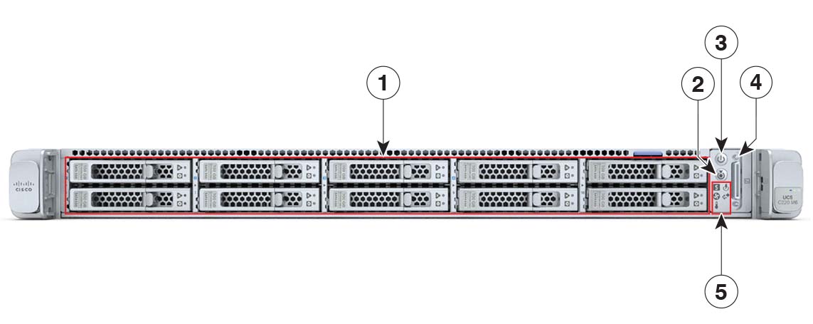
Front panel:
|
|
Modular LOM
|
One dedicated socket (x16 PCIe lane) that can be used to add an mLOM card for additional rear-panel connectivity. As an optional
hardware configuration, the Cisco CNIC mLOM module supports two 100G QSFP+ ports or four 25 Gbps Ethernet ports.
|
|
Power
|
|
|
ACPI
|
Supports advanced configuration and power interface (ACPI) 4.0 standard
|
|
Front Panel
|
The front panel provides status indications and control buttons
|
|
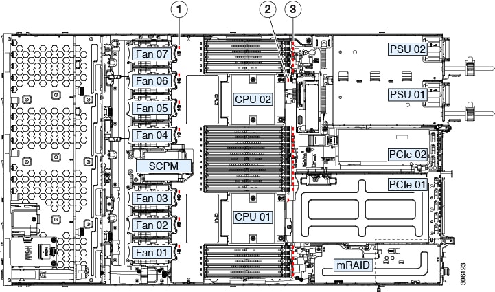
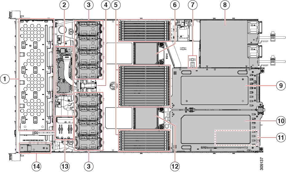
Cooling
|
Eight hot-swappable fan modules for front-to-rear cooling
|
|
InfiniBand
|
In addition to Fibre Channel, Ethernet, and other industry-standards, the PCI slots in this server support the InfiniBand
architecture.
|
|
Interfaces
|
Rear panel:
-
One 1G base-T RJ-45 ? management port
-
Two 10G base-T LOM ports
-
One RS-232 serial port (RJ45 connector)
-
One DB15 VGA connector
-
Two USB 3.0 port connectors
-
One flexible modular LAN on motherboard (mLOM) slot that can accommodate various interface cards
Front panel:
|
|
Integrated Management Processor
|
Baseboard Management Controller running Cisco IMC firmware.
Depending on your Cisco IMC settings, Cisco IMC can be accessed through the 1-GE dedicated management port, the 1GE/10GE LOM
ports, or a Cisco virtual interface card (VIC).
|
|
Storage Controllers
|
The appliance has a dedicated internal mRAID riser that supports a PCIe-style Cisco modular RAID controller card (SAS/SATA).
|
|
Modular LAN over Motherboard (mLOM) slot
|
The dedicated mLOM slot on the motherboard can accommodate the following cards:
|


 Feedback