Installing the Appliance

Installation Warnings and Guidelines


Warning


IMPORTANT SAFETY INSTRUCTIONS

This warning symbol means danger. You are in a situation that could cause bodily injury. Before you work on any equipment, be aware of the hazards involved with electrical circuitry and be familiar with standard practices for preventing accidents. Use the statement number provided at the end of each warning to locate its translation in the translated safety warnings that accompanied this device.

Statement 1071


Warning


To prevent the system from overheating, do not operate it in an area that exceeds the maximum recommended ambient temperature of: 35° C (95° F).

Statement 1047


Warning


The plug-socket combination must be accessible at all times, because it serves as the main disconnecting device.

Statement 1019


Warning


This product relies on the building’s installation for short-circuit (overcurrent) protection. Ensure that the protective device is rated not greater than: 250 V, 15 A.

Statement 1005


Warning


Installation of the equipment must comply with local and national electrical codes.

Statement 1074


Warning


This unit is intended for installation in restricted access areas. A restricted access area can be accessed only through the use of a special tool, lock, and key, or other means of security.

Statement 1017


Caution


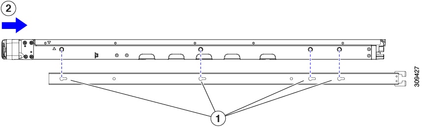
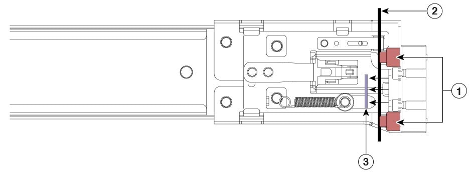
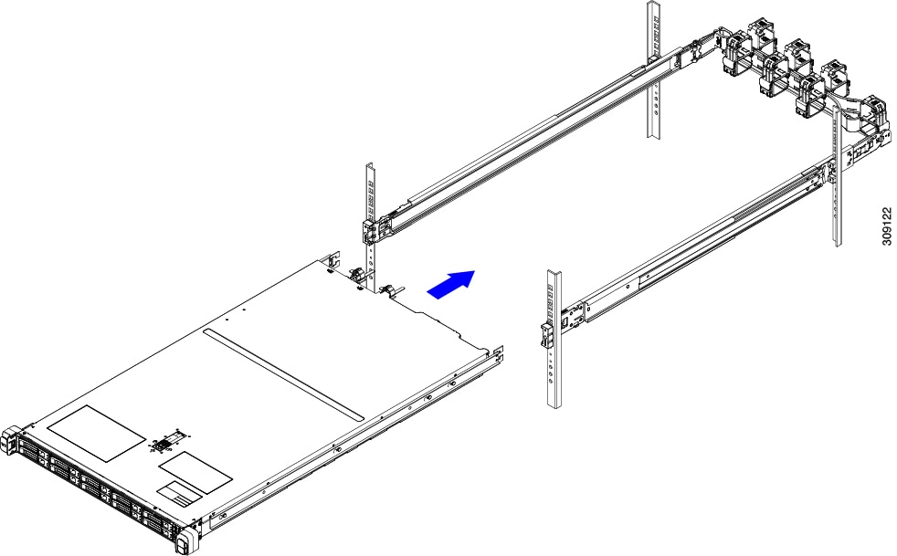
Rack the appliance using rail kits to ensure proper airflow. Physically placing the units on top of one another or stacking them without the use of rail kits, blocks the air vents on top of the servers, which could result in overheating, higher fan speeds, and higher power consumption. We recommend that you mount your servers on rail kits while installing on the rack because these rails provide the minimal spacing required between the servers. No additional spacing between the servers is required when you mount the units using rail kits.


Follow these guidelines while installing the appliance:

  • Ensure that there is adequate space around the appliance to allow for easy access and adequate airflow.

  • Ensure that the air-conditioning meets the thermal requirements listed in Environmental Specifications.

  • Ensure that the cabinet or rack meets the requirements listed in Rack Requirements.

  • Ensure that the site power meets the power requirements listed in Power Specifications. You can use an uninterruptible power supply (UPS) to protect against power failures.

Rack Requirements

The rack must be of the following type:

  • A standard 19-inch (48.3-cm) wide, four-post EIA rack, with mounting posts that conform to English universal hole spacing, per section 1 of ANSI/EIA-310-D-1992.

  • The rack-post holes can be square 0.38-inch (9.6 mm), round 0.28-inch (7.1 mm), #12-24 UNC, or #10-32 UNC when you use the Cisco-supplied slide rails.

  • The minimum vertical rack space per server must be one rack unit (RU), equal to 1.75 inch (44.45 mm).

Rack Installation Tools Required

The slide rails sold by Cisco Systems for this appliance do not require tools for installation.

Slide Rail and Cable Management Arm Dimensions

The slide rails for this appliance have an adjustment range of 24 to 36 inches (610 to 914 mm).

The optional cable management arm (CMA) adds additional length requirements:

  • The additional distance from the rear of the server to the rear of the CMA is 5.4 inches (137.4 mm).

  • The total length of the server, including the CMA, is 35.2 inches (894 mm).

Installing the Appliance in a Rack

This section describes how to install the appliance in a rack using the supported rail kit that is sold by Cisco.


Warning


To prevent bodily injury when mounting or servicing this unit in a rack, you must take special precautions to ensure that the system remains stable. The following guidelines are provided to ensure your safety:

This unit should be mounted at the bottom of the rack if it is the only unit in the rack.

When mounting this unit in a partially filled rack, load the rack from the bottom to the top with the heaviest component at the bottom of the rack.

If the rack is provided with stabilizing devices, install the stabilizers before mounting or servicing the unit in the rack.

Statement 1006


Procedure


Step 1

Attach the inner rails to the sides of the appliance:

  1. Align an inner rail with one side of the appliance so that the three keyed slots in the rail align with the three pegs on the side of the appliance.

  2. Set the keyed slots over the pegs, and then slide the rail toward the front to lock it in place on the pegs.

  3. Install the second inner rail to the opposite side of the appliance.

Figure 1. Attaching the Inner Rail to the Side of the Appliance

1

Keyed slots in rail

2

Front of appliance slides into keyed slots

Step 2

Open the front securing plate on both slide-rail assemblies. The front end of the slide-rail assembly has a spring-loaded securing plate that must be open before you can insert the mounting pegs into the rack-post holes.

Outside the assembly, push the green-arrow button toward the rear to open the securing plate.

Figure 2. Front Securing Mechanism, Inside of Front End

1

Front mounting pegs

3

Securing plate shown pulled back to the open position

2

Rack post between mounting pegs and opened securing plate

-

Step 3

Install the outer slide rails into the rack:

  1. Align one slide-rail assembly front end with the front rack-post holes that you want to use.

    The slide rail front-end wraps around the outside of the rack post and the mounting pegs enter the rack-post holes from the outside-front.

    Note

     
    The rack post must be between the mounting pegs and the open securing plate.
  2. Push the mounting pegs into the rack-post holes from the outside-front.

  3. Press the securing plate release button, marked Push. The spring-loaded securing plate closes to lock the pegs in place.

  4. Adjust the slide-rail length, and then push the rear mounting pegs into the corresponding rear rack-post holes.

    The rear mounting pegs enter the rear rack-post holes from the inside of the rack post.

  5. Attach the second slide-rail assembly to the opposite side of the rack. Ensure that the two slide-rail assemblies are at the same height and are level front-to-back.

  6. Pull the inner slide rails on each assembly, toward the rack front until they hit the internal stops and lock in place.

Step 4

Insert the appliance into the slide rails:

Caution

 
This appliance can weigh up to 60 pounds (27 kilograms) when fully loaded with components. We recommend that you use a minimum of two people or a mechanical lift when lifting the appliance. Attempting this procedure alone could result in personal injury or equipment damage.
  1. Align the rear ends of the inner rails that are attached to the appliance sides with the front ends of the empty slide rails on the rack.

  2. Push the inner rails into the slide rails on the rack until they stop at the internal stops.

  3. Slide the inner-rail release clip toward the rear on both inner rails, and then continue pushing the appliance into the rack until its front slam latches engage with the rack posts.

Figure 3. Inner-Rail Release Clip

1

Inner-rail release clip

3

Outer slide rail attached to rack post

2

Inner rail attached to appliance and inserted into outer slide rail

-

Step 5

(Optional) Secure the appliance in the rack more permanently by using the two screws that are provided with the slide rails. Perform this step if you plan to move the rack with the appliance installed.

With the appliance fully pushed into the slide rails, open a hinged slam latch lever on the front of the appliance and insert a screw through the hole that is under the lever. The screw threads into the static part of the rail on the rack post and prevents the appliance from being pulled out. Repeat for the opposite slam latch.

Step 6

(Optional) If applicable, do the following:

  1. Attach the cable management arm. See Installing the Cable Management Arm (Optional) or Reversing the Cable Management Arm (Optional).

  2. Attach the locking bezel.


Installing the Cable Management Arm (Optional)


Note


The cable management arm (CMA) is reversible left-to-right. To reverse the CMA, see Reversing the Cable Management Arm (Optional) before installation.

Procedure


Step 1

With the appliance pushed fully into the rack, slide the CMA tab of the CMA arm that is farthest from the appliance onto the end of the stationary slide rail that is attached to the rack post. Slide the tab over the end of the rail until it clicks and locks.

Figure 4. Attaching the CMA to the Rear Ends of the Slide Rails

1

CMA tab on arm farthest from appliance attaches to end of stationary outer slide rail.

3

CMA tab on width-adjustment slider attaches to end of stationary outer slide rail.

2

CMA tab on arm closest to the appliance attaches to end of inner slide rail attached to appliance.

4

Rear of appliance

Step 2

Slide the CMA tab, which is closest to the appliance, over the end of the inner rail that is attached to the appliance. Slide the tab over the end of the rail until it clicks and locks

Step 3

Pull out the width-adjustment slider that is at the opposite end of the CMA assembly until it matches the width of your rack.

Step 4

Slide the CMA tab that is at the end of the width-adjustment slider onto the end of the stationary slide rail that is attached to the rack post. Slide the tab over the end of the rail until it clicks and locks.

Step 5

Open the hinged flap at the top of each plastic cable guide and route your cables through the cable guides, as required.


Reversing the Cable Management Arm (Optional)

Procedure


Step 1

Rotate the entire CMA assembly 180 degrees, left-to-right. The plastic cable guides must remain pointing upward.

Step 2

Flip the tabs at the ends of the CMA arms so that they point toward the rear of the appliance.

Step 3

Pivot the tab that is at the end of the width-adjustment slider. Depress and hold the metal button on the outside of the tab and pivot the tab 180 degrees so that it points toward the rear of the appliance.

Figure 5. Reversing the CMA

1

CMA tab at the end of width-adjustment slider

2

Metal button outside the tab


Initial Setup

This section describes how to connect to the system for initial setup.

Appliance Default Settings

The appliance is shipped with these default settings:

  • The NIC mode is Shared LOM EXT.

    Shared LOM EXT mode enables the 1-Gb or10-Gb Ethernet ports and the ports on any installed Cisco virtual interface card (VIC) to access the Cisco Integrated Management Interface (Cisco IMC). To use the 10/100/1000 dedicated management ports to access Cisco IMC, you can connect to the appliance and change the NIC mode as described in Setting Up the System with the Cisco IMC Configuration Utility.

    For information about the browsers that are supported for Cisco IMC, see Release Notes for Cisco UCS E-Series M6 Servers.

  • The NIC redundancy is Active-Active. All Ethernet ports are utilized simultaneously.

  • DHCP is enabled.

  • IPv4 is enabled.

Connection Methods

There are two methods for connecting to the system for initial setup:

  • Local setup: Use this procedure to connect a keyboard and monitor directly to the system for setup. This procedure can use a KVM cable or the ports at the rear of the appliance.

  • Remote setup: Use this procedure to perform setup through your dedicated management LAN.


    Note


    To configure the system remotely, you must have a DHCP server on the same network as the system. Your DHCP server must be preconfigured with the range of MAC addresses for this server node. The MAC address is printed on a label that is on the pull-out asset tag on the front panel. This server node has a range of six MAC addresses assigned to the Cisco IMC. The MAC address printed on the label is the beginning of the range of six contiguous MAC addresses.

Connecting to the Appliance Locally for Setup

This procedure requires the following equipment:

  • VGA monitor

  • USB keyboard

  • Either the supported Cisco KVM cable or a USB cable and VGA DB-15 cable

Procedure


Step 1

Attach a power cord to each power supply in your appliance, and then attach each power cord to a grounded power outlet.

Wait for approximately two minutes for the appliance to boot to standby power during the initial setup. You can verify the system's power status by looking at the system Power Status LED on the front panel. The system is in standby power mode when the LED is amber.

Step 2

Connect a USB keyboard and VGA monitor to the appliance using one of the following methods:

  • Connect an optional KVM cable to the KVM connector on the front panel. Connect your USB keyboard and VGA monitor to the KVM cable.

  • Connect a USB keyboard and VGA monitor to the corresponding connectors on the rear panel.

Step 3

Open the Cisco IMC Configuration Utility:

  1. Press and hold the front panel power button for four seconds to boot the appliance.

  2. Press F8 when prompted to open the Cisco IMC Configuration Utility.

    When you access the Cisco IMC Configuration Utility for the first time, you are prompted to change the default password, which is password. The Strong Password feature is enabled.

    The following are the requirements for a strong password:

    • The password can have a minimum of 8 characters and a maximum of 14 characters.

    • The password must not contain the user’s name.

    • The password must contain characters from three of the following categories:

      • English uppercase letters (A through Z)

      • English lowercase letters (a through z)

      • Base 10 digits (0 through 9)

      • Non-alphabetic characters !, @, #, $, %, ^, &, *, -, _, =, “

Step 4

Continue this procedure by following the instructions provided in Setting Up the System with the Cisco IMC Configuration Utility.


Connecting to the Appliance Remotely for Setup

This procedure requires the following equipment:

  • One RJ-45 Ethernet cable that is connected to your management LAN.

Before you begin

To configure the system remotely, you must have a DHCP server on the same network as the system. Your DHCP server must be preconfigured with the range of MAC addresses for this server node. The MAC address is printed on a label that is on the pull-out asset tag on the front panel. This server node has a range of six MAC addresses assigned to the Cisco IMC. The MAC address printed on the label is the beginning of the range of six contiguous MAC addresses.

Procedure


Step 1

Attach a power cord to each power supply in your appliance, and then attach each power cord to a grounded power outlet.

Wait for approximately two minutes for the appliance to boot to standby power during the initial setup. You can verify the system's power status by looking at the system Power Status LED on the front panel. The system is in standby power mode when the LED is amber.

Step 2

Plug your management Ethernet cable into the dedicated management port on the rear panel.

Step 3

Allow your preconfigured DHCP server to assign an IP address to the server node.

Step 4

Use the assigned IP address to access and log in to the Cisco IMC for the server node.

Note

 
The default username for the server is admin. The default password is password.

Step 5

On the Cisco IMC Server Summary window, click Launch KVM Console.

A KVM console window opens.

Step 6

On the Cisco IMC Summary window, click Power Cycle Server.

The system reboots.

Step 7

Open the KVM console window.

Note

 
The KVM console window must be an active window for the following keyboard actions to work.

Step 8

When prompted, press F8 to enter the Cisco IMC Configuration Utility.

Note


When you open the Cisco IMC Configuration Utility for the first time, the Strong Password feature is enabled, and you are prompted to change the default password. The default password is password.

The following are the requirements for a strong password:

  • The password can have a minimum of 8 characters and a maximum of 14 characters.

  • The password must not contain the user’s name.

  • The password must contain characters from three of the following categories:

    • English uppercase letters (A through Z)

    • English lowercase letters (a through z)

    • Base 10 digits (0 through 9)

    • Nonalphabetic characters !, @, #, $, %, ^, &, *, -, _, =, “

Step 9

Continue this procedure by following the instructions provided in Setting Up the System with the Cisco IMC Configuration Utility.


Setting Up the System with the Cisco IMC Configuration Utility

Before you begin

The following procedure can be performed after you connect to the system and open the Cisco IMC Configuration Utility.


Note


You must use the versions of Cisco IMC firmware from the Cisco ISE download site, which are qualified versions for use with the SNS hardware appliances. Versions of Cisco IMC for UCS are not compatible. Newer versions of Cisco IMC are developed for SNS hardware appliances after they are developed for UCS.


Procedure


Step 1

Set the NIC mode to choose the ports that are to be used to access Cisco IMC for server management:

  • Shared LOM EXT (default): This is the shared LOM extended mode, the factory default setting. With this mode, the Shared LOM and Cisco Card interfaces are both enabled. If you select this option, you must select the default Active-Active NIC redundancy setting in Step 2.

  • Shared LOM: The 1-Gb or 10-Gb Ethernet ports are used to access Cisco IMC. If you select this option, you must select the Active-Active or Active-standby NIC redundancy setting in Step 2.

  • Dedicated: The dedicated management port is used to access Cisco IMC. If you select this option, you must select the None NIC redundancy setting in Step 2.

  • Cisco Card: The Virtual Interface Card (VIC) ports are used to access the Cisco IMC. If you select this option, you must select the Active-Active or Active-standby NIC redundancy setting in Step 2.

  • VIC Slot: Only if you use the Cisco Card NIC mode, you must select this setting to match the location where your VIC is installed.

Step 2

Choose one of the following options for NIC redundancy:

  • None: The Ethernet ports operate independently and do not fail over if there is a problem. This setting can be used only with the Dedicated NIC mode.

  • Active-standby: If an active Ethernet port fails, traffic fails over to a standby port. Shared LOM and Cisco Card modes can use the Active-standby or Active-active settings.

  • Active-active (default): All Ethernet ports are utilized simultaneously. You must use only this NIC redundancy setting if you have selected the Shared LOM EXT mode. Shared LOM and Cisco Card modes can use the Active-standby or Active-active settings.

Step 3

Choose whether to enable DHCP for dynamic network settings, or to enter static network settings.

Note


Before you enable DHCP, you must preconfigure your DHCP server with the range of MAC addresses for this server. The MAC address is printed on a label at the rear of the server. This server has a range of six MAC addresses assigned to Cisco IMC. The MAC address printed on the label is the beginning of the range of six contiguous MAC addresses.

The Static IPv4 and IPv6 Settings include the following:

  • Cisco IMC IP address: For IPv6, valid values are 1 to 127.

  • Gateway: For IPv6, if you do not know the gateway, you can set it as none by entering :: (two colons).

  • Preferred DNS Server Address: For IPv6, you can set this as none by entering :: (two colons).

Step 4

(Optional) Configure VLAN settings.

Step 5

(Optional) Set a hostname for the server.

Step 6

(Optional) Enable dynamic DNS (DDNS) and set a DDNS domain.

Step 7

(Optional) If you check the Factory Default check box, the server reverts to the factory defaults.

Step 8

(Optional) Set a default user password.

Note

 
The factory default username for the server is admin. The default password is password.

Step 9

(Optional) Enable auto-negotiation of port settings, or set the port speed and duplex mode manually.

Note

 
Auto-negotiation is applicable only when you use the Dedicated NIC mode. Auto-negotiation sets the port speed and duplex mode automatically based on the switch port to which the server is connected. If you disable auto-negotiation, you must set the port speed and duplex mode manually.

Step 10

(Optional) Reset the port profiles and the port name.

Step 11

Press F5 to refresh the settings. You might have to wait for about 45 seconds until the new settings appear along with the message "Network settings configured" is displayed before moving to the next step.

Step 12

Press F10 to save your settings and reboot the server.

Note

 
If you chose to enable DHCP, the dynamically assigned IP and MAC addresses are displayed on the console screen when you boot the server.

Updating the BIOS and Cisco IMC Firmware


Caution


When you upgrade the BIOS firmware, you must also upgrade the Cisco IMC firmware to the corresponding version. If you don't do this, the server will not boot.


Cisco provides the Cisco Host Upgrade Utility to assist with simultaneously upgrading the BIOS, Cisco IMC, and other firmware to compatible levels.

The server uses the firmware obtained from and certified by Cisco. Cisco provides release notes with each firmware image.

You can upgrade the Cisco IMC and BIOS firmware by using the Cisco IMC GUI or CLI.

Accessing the System BIOS

Procedure


Step 1

Enter the BIOS Setup Utility by pressing the F2 key when prompted during the initial setup.

Note

 
The version and build of the current BIOS are displayed on the main page of the utility.

Step 2

Use the arrow keys to select the BIOS menu page.

Step 3

Highlight the field to be modified by using the arrow keys.

Step 4

Press Enter to select the field that you want to change, and then modify the value in the field.

Step 5

Press the right arrow key until the Exit menu screen is displayed.

Step 6

Follow the instructions on the Exit menu screen to save your changes and exit the setup utility (or press F10). You can exit without saving the changes by pressing Esc.


Smart Access Serial

This server supports the Smart Access Serial feature. This feature allows you to switch between the host serial and the Cisco IMC CLI. This feature has the following requirements:

  • A serial cable connection, which can use either the RJ-45 serial connector on the server rear panel, or a DB-9 connection when using the KVM cable on the front-panel KVM console connector.

  • Console redirection must be enabled in the server BIOS.

  • Terminal type must be set to VT100+ or VTUFT8.

  • Serial-over-LAN (SOL) must be disabled.

  • To switch from host serial to Cisco IMC CLI, press Esc+9.

    You must enter your Cisco IMC credentials to authenticate the connection.

  • To switch from Cisco IMC CLI to host serial, press Esc+8.


    Note


    You cannot switch to Cisco IMC CLI if the serial-over-LAN (SOL) feature is enabled.


  • After a session is created, it is shown in the CLI or web GUI by the name serial.

Configuring RAID Controller After Replacing HDD/SSD

Perform the following procedure to configure the RAID controller cards after replacing the HDD or SSD.

Procedure


Step 1

Replace the existing HDD or SSD:

  1. Log in to the Cisco SNS 3700 series appliance.

  2. Click the Menu icon in the top-left corner.

  3. Choose Storage > Cisco RAID Controller > Controller Info.

  4. Click Clear Boot Drive.

  5. Click OK to clear the boot drive.

  6. Click Virtual Drive Info.

  7. In the Virtual Drives window, select the virtual drive and click Delete Virtual Drive.

  8. Click Physical Drive Info.

  9. In the Physical Drives window, select the physical drives and click Prepare for Removal.

    Note


    Cisco ISE is uninstalled when you delete the drives. You have to re-install Cisco ISE after replacing the HDD or SSD.

Step 2

Configure RAID controller:

  1. Log in to the Cisco SNS 3700 series appliance.

  2. Click the Menu icon in the top-left corner.

  3. Choose Storage > Cisco RAID Controller > Controller Info.

  4. Click Create Virtual Drive from Unused Physical Drives.

    Note


    When the drives are inserted they might be shown as being configured in Just a Bunch Of Disks (JBOD) mode. You must unconfigure the drives before adding the drives to a virtual disk.

  5. From the RAID Level drop-down list, select RAID 10 for SNS 3755 and SNS 3795. Select RAID 0 for SNS 3715.

  6. In the Create Drive Groups section, select the drives that are to be grouped together and move them to the Drive Groups pane. You can create different groups based on your requirements.

  7. In the Virtual Drive Properties section, from the Write Policy drop-down list, select Write Back Good BBU.

    Figure 6. Virtual Drive Properties
  8. Click OK.

    You can verify whether the RAID configuration is successful in the Virtual Drive Info tab.

  9. Install Cisco ISE on the newly replaced HDD or SSD.


For more information, see the Chapter "Configuring RAID Levels" in the Cisco UCS Server Configuration Utility User Guide.

Enabling Drive Security for SED

You can enable Local Key Management or Remote Key Management for a SED.

Local Key Management

To enable Local Key Management for a SED, perform the following steps:

Procedure


Step 1

Log in to the Cisco SNS 3700 series appliance.

Step 2

Click the Menu icon in the top-left corner.

Step 3

Choose Storage > Cisco 12G SAS RAID Controller > Controller Info.

Step 4

Click Enable Drive Security.

Step 5

Click the Local Key Management radio button.

Step 6

Enter the security key.

Step 7

Click Save.

Step 8

Click Virtual Drive Info.

Step 9

In the Virtual Drives window, select the virtual drive and click Secure Virtual Drive.

A lock icon appears in the Virtual Drive Number column for the drive for which drive security is enabled.


Remote Key Management

To enable Remote Key Management for a SED, perform the following steps:

Procedure


Step 1

Click the Menu icon in the top-left corner.

Step 2

Choose Admin > Security Management > Secure Key Management.

Step 3

Enter the Key Management Interoperability Protocol (KMIP) server details.

Step 4

Attach the root CA certificate, client certificate, and client private key certificate.

Step 5

Check the Enable Secure Key Management check box.

Step 6

Choose Storage > Cisco 12G SAS RAID Controller > Controller Info.

Step 7

Click Enable Drive Security.

Step 8

Click the Remote Key Management radio button.

Step 9

Click Save.

Step 10

Click Virtual Drive Info.

Step 11

In the Virtual Drives window, select the virtual drive and click Secure Virtual Drive.

A lock icon appears in the Virtual Drive Number column for the drive for which drive security is enabled.