Deploy the Firewall Threat Defense Virtual on GCP

You can deploy the Firewall Threat Defense Virtual on the Google Cloud Platform (GCP), a public cloud computing service that enables you to run your applications in a highly-available, hosted environment offered by Google.

You see the GCP project information in the GCP console Dashboard.

  • Make sure that you select your GCP project in the Dashboard if that is not already selected.

  • To access the Dashboard, click Navigation menu > Home > Dashboard.

You log into the GCP Console, search the GCP Marketplace for the Cisco Firepower NGFW virtual firewall (NGFWv) offering, and launch the Firewall Threat Defense Virtual instance. The following procedures describe how to prepare your GCP environment and launch the Firewall Threat Defense Virtual instance to deploy the Firewall Threat Defense Virtual.

Overview

The Firewall Threat Defense Virtual runs the same software as physical Secure Firewall Threat Defense (formerly Firepower Threat Defense) to deliver proven security functionality in a virtual form factor. The Firewall Threat Defense Virtual can be deployed in the public GCP. It can then be configured to protect virtual and physical data center workloads that expand, contract, or shift their location over time.

System Requirements

Select the Google virtual machine type and size to meet your Firewall Threat Defense Virtual needs. Currently, the Firewall Threat Defense Virtual supports both compute-optimized and general purpose machine types (standard, high-memory, and high-CPU machine types).


Note


Supported machine types may change without notice.


Table 1. Supported Compute-Optimized Machine Types

Compute-Optimized Machine Types

Attributes

vCPUs

RAM (GB)

vNICs

c2-standard-4

4

16 GB

4

c2-standard-8

8

32 GB

8

c2-standard-16

16

64 GB

8

Table 2. Supported General Purpose Machine Types

General Purpose Machine Types

Attributes

vCPUs

RAM (GB)

vNICs

n1-standard-4

4

15

4

n1-standard-8

8

30

8

n1-standard-16

16

60

8

n2-standard-4

4

16

4

n2-standard-8

8

32

8

n2-standard-16

16

64

8

n2-highmem-4

4

32

4

n2-highmem-8

8

64

8

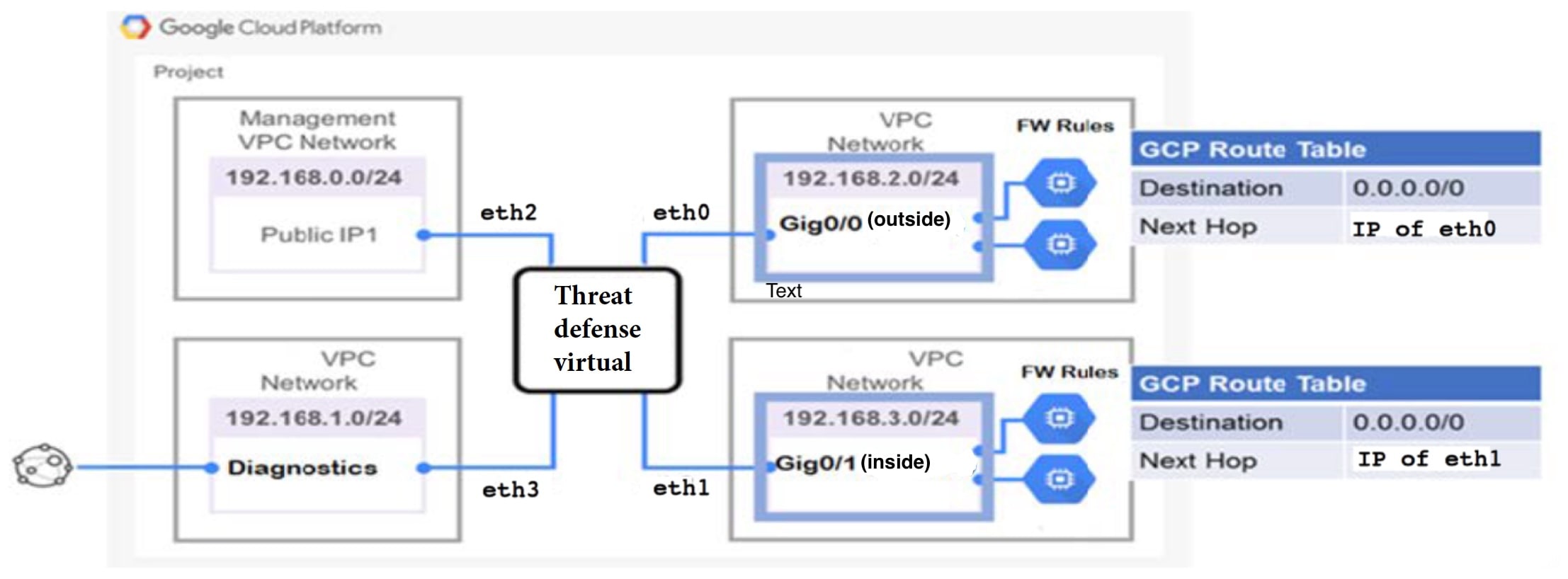
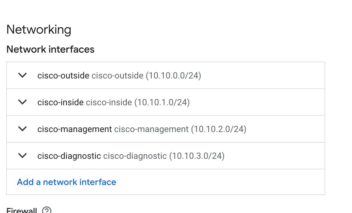
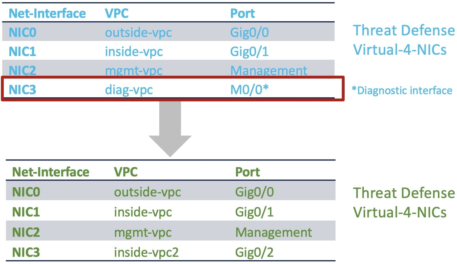
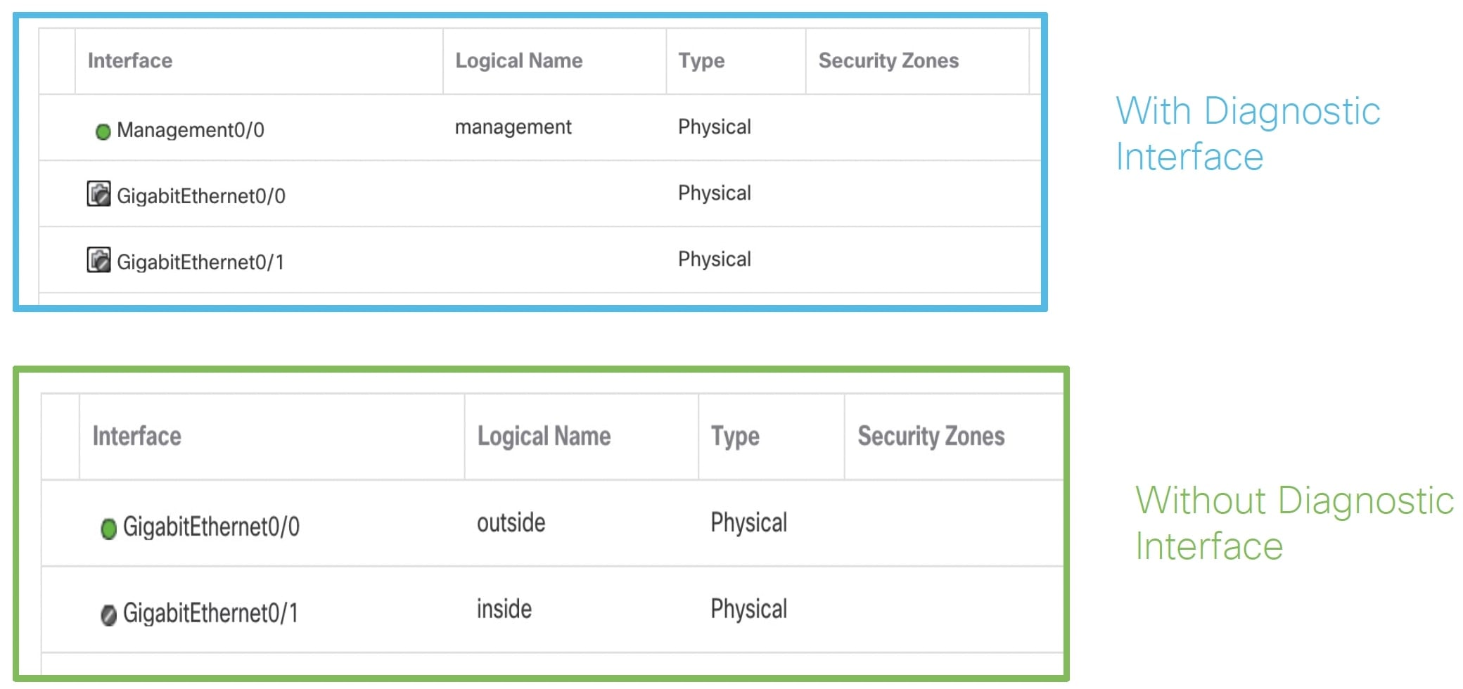
  • The Firewall Threat Defense Virtual requires a minimum of 4 interfaces.

  • The maximum supported vCPUs is 16.

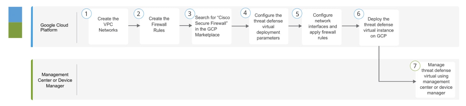
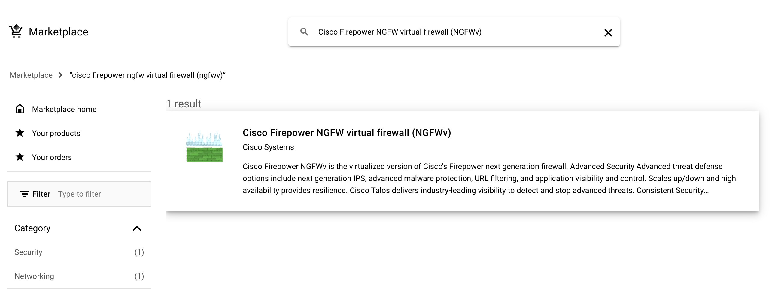
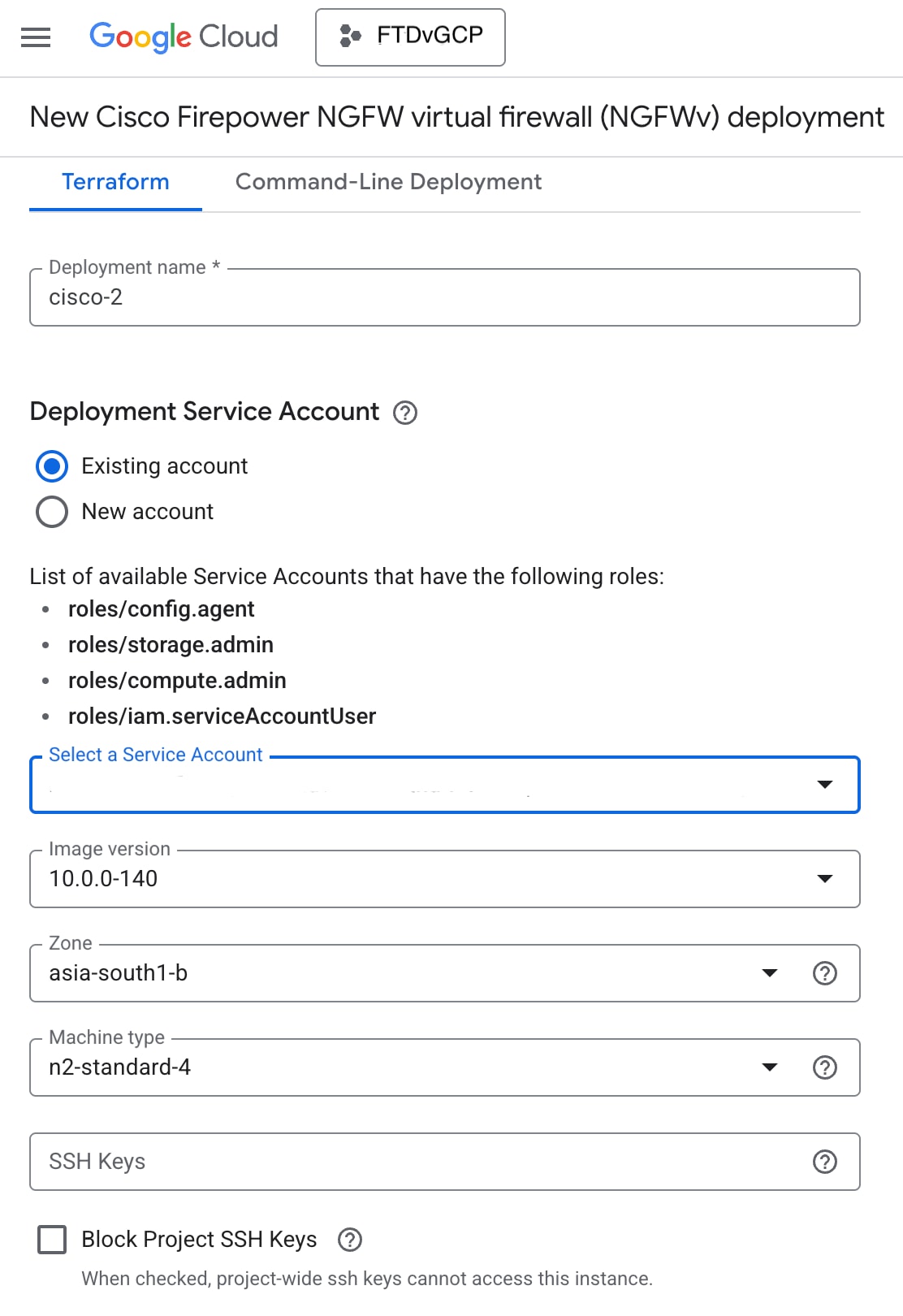
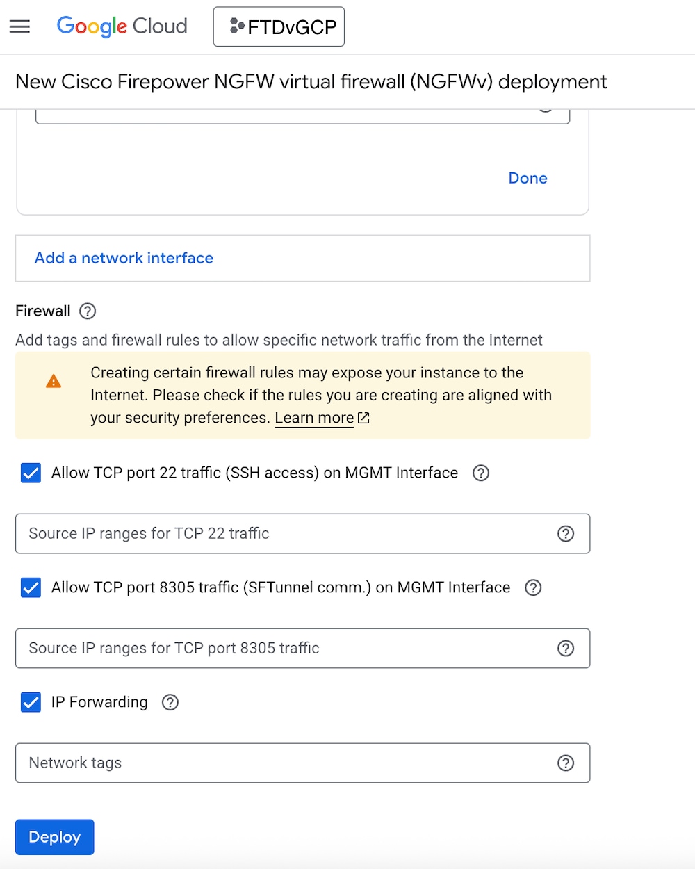
You create an account on GCP, launch a VM instance using the Cisco Firepower NGFW virtual firewall (NGFWv) offering on the GCP Marketplace, and choose a GCP machine type.

End-to-End Procedure

The following flowchart illustrates the workflow for deploying Threat Defense Virtual on Google Cloud Platform.

Workspace

Steps

GCP

Deploy the Threat Defense Virtual on GCP: Create the VPC Network (VPC Networks > Subnet > Region > IP address range).

GCP

Deploy the Threat Defense Virtual on GCP: Create the firewall rules (Networking > VPC networks > Firewall > Create Firewall Rule).

GCP

Deploy the Threat Defense Virtual on GCP: Search for “Cisco Secure Firewall” in the GCP Marketplace.

GCP

Deploy the Threat Defense Virtual on GCP: Configure the threat defense virtual deployment parameters.

GCP

Deploy the Threat Defense Virtual on GCP: Configure network interfaces and apply firewall rules.

GCP

Deploy the Threat Defense Virtual on GCP: Deploy the Threat Defense Virtual on GCP.

Management Center or Device Manager

Manage the Firewall Threat Defense Virtual:

Prerequisites

Interface requirements

  • Management interfaces (2) — One used to connect the Firewall Threat Defense Virtual to the Firewall Management Center, second used for diagnostics; cannot be used for through traffic.

  • Traffic interfaces (2) — Used to connect the Firewall Threat Defense Virtual to inside hosts and to the public network.

  • From Secure Firewall version 7.4.1, you can remove the diagnostic interface and deploy the Threat Defense Virtual on GCP with a minimum of 4 interfaces in the following combination – 1 management, and 3 data interfaces. We recommend that you deploy the Threat Defense Virtual on GCP without the diagnostic interface from Secure Firewall version 7.4.1. For more information, see About Deployment of Threat Defense Virtual without Diagnostic Interface on GCP.

Communications paths

  • Public IPs for access into the Firewall Threat Defense Virtual.

Guidelines and Limitations for the Firewall Threat Defense Virtual and GCP

Supported Features

  • Deployment in the GCP Compute Engine

  • Maximum of 16 vCPUs per instance

  • Routed mode (default)

  • Licensing – Only BYOL is supported

  • Clustering (7.2 or later). For more information, see Clustering for Threat Defense Virtual in a Public Cloud

  • On Secure Firewall 7.1 and earlier versions, only Firewall Management Center is supported. Starting from Secure Firewall version 7.2, Firewall Device Manager is also supported.

Performance Tiers for Firewall Threat Defense Virtual Smart Licensing

The Firewall Threat Defense Virtual supports performance-tiered licensing that provides different throughput levels and VPN connection limits based on deployment requirements.

Table 3. Firewall Threat Defense Virtual Licensed Feature Limits Based on Entitlement

Performance Tier

Device Specifications (Core/RAM)

Rate Limit

RA VPN Session Limit

FTDv5, 100Mbps

4 core/8 GB

100Mbps

50

FTDv10, 1Gbps

4 core/8 GB

1Gbps

250

FTDv20, 3Gbps

4 core/8 GB

3Gbps

250

FTDv30, 5Gbps

8 core/16 GB

5Gbps

250

FTDv50, 10Gbps

12 core/24 GB

10Gbps

750

FTDv100, 16Gbps

16 core/32 GB

16Gbps

10,000

See the "Licensing " chapter in the Cisco Secure Firewall Management Center Administration Guide for guidelines when licensing your Firewall Threat Defense Virtual device.


Note


To change the vCPU/memory values, you must first power off the Firewall Threat Defense Virtual device.


Performance Optimizations

To achieve the best performance out of the Firewall Threat Defense Virtual, you can make adjustments to the both the VM and the host. See Virtualization Tuning and Optimization on GCP for more information.

Receive Side Scaling—The Firewall Threat Defense Virtual supports Receive Side Scaling (RSS), which is a technology utilized by network adapters to distribute network receive traffic to multiple processor cores. Supported on Version 7.0 and later. See Multiple RX Queues for Receive Side Scaling (RSS) for more information.

Allocation of Receive and Transmit Queues

A specific number of receive (RX) and transmit (TX) queues is assigned to each vNIC to process network packets. Based on the type of network interface used - VirtIO or gVNIC, Google Cloud uses an algorithm to assign a default number of RX and TX queues per vNIC.

The method used by GCP to assign queues to vNICs is as follow:

  • VirtIO - Number of vCPUs divided by the number of vNICs, and discard any remainder value.

    For example, if the VM has 16 vCPUs and 4 vNICs, the number of queues assigned per vNIC is [16/4] = 4.

  • gVNIC - Number of vCPUs divided by number of vNICs, and further divide the result by 2

    For example, if the VM has 128 vCPUs and 2 vNICs, the number of queues assigned is [128/2]/2 = 32.

You can also customize the number of queues that are allocated to each vNIC when you create a new VM by using the Compute Engine API. However, you have to adhere to the following rules if you want to do this-

  • Minimum queue count: One per vNIC.

  • Maximum queue count: This number is the lower of the vCPU count or the maximum queue count per vNIC, based on the driver type:

    • Maximum queue count is 32 if you are using VirtIO or a custom driver

    • Maximum queue count is 16 if you are using gVNIC

  • If you customize the number of queues that is assigned to all the vNICs of the VM, the total number of queue assignments must be less than or equal to the number of vCPUs assigned to the VM instance.

For more information and examples on default and custom queue allocation, see Default queue allocation and Custom queue allocation.

Snort

  • If you are observing abnormal behavior such as Snort taking a long time to shut down, or the VM being slow in general or when a certain process is executed, collect logs from the Firewall Threat Defense Virtual and the VM host. Collection of overall CPU usage, memory, I/O usage, and read/write speed logs will help troubleshoot the issues.

  • High CPU and I/O usage is observed when Snort is shutting down. If a number of Firewall Threat Defense Virtual instances have been created on a single host with insufficient memory and no dedicated CPU, Snort will take a long time to shut down which will result in the creation of Snort cores.

Upgrade

Upgrade of Firewall Threat Defense Virtual in GCP from Secure Firewall version 7.1 to 7.2 is not supported. Perform a reimage if you are upgrading from Secure Firewall version 7.1 to 7.2.

Unsupported Features

  • IPv6

  • Firewall Threat Defense Virtual native HA

  • Transparent/inline/passive modes

  • Jumbo Frames

NIC Mapping to Data Interfaces

On Secure Firewall version 7.1 and earlier releases, the mapping of Network Interface Cards (NICs) to data interfaces is as given below:

  • nic0 – Management interface

  • nic1 – Diagnostic interface

  • nic2 – Gigabit Ethernet 0/0

  • nic3 – Gigabit Ethernet 0/1

From Secure Firewall version 7.2, a data interface is required on nic0 to facilitate movement of north-south traffic because the external load balancer (ELB) forwards packets only to nic0.

The mapping of NICs and data interfaces on Secure Firewall version 7.2 is as given below:

  • nic0 – Gigabit Ethernet 0/0

  • nic1 – Gigabit Ethernet 0/1

  • nic2 – Management interface

  • nic3 – Diagnostic interface

  • nic4 – Gigabit Ethernet 0/2

    .

    .

    .

  • nic(N-2) – Gigabit Ethernet 0/N-4

  • nic(N-1) – Gigabit Ethernet 0/N-3

From Secure Firewall version 7.4.1, you can also deploy Threat Defense Virtual without the diagnostic interface. In such a scenario, the mapping of NICs and data interfaces is as given below:

  • nic0 – Gigabit Ethernet 0/0

  • nic1 – Gigabit Ethernet 0/1

  • nic2 – Management interface

  • nic3 – Gigabit Ethernet 0/2

  • nic4 – Gigabit Ethernet 0/3

    .

    .

    .

  • nic(N-2) – Gigabit Ethernet 0/N-3

  • nic(N-1) – Gigabit Ethernet 0/N-2

Sample Network Topology

The following figure shows the recommended topology for the Firewall Threat Defense Virtual in Routed Firewall Mode with 4 subnets configured in GCP for the Firewall Threat Defense Virtual (management, diagnostic, inside, and outside).

Figure 1. Sample Firewall Threat Defense Virtual on GCP Deployment

How to Manage Secure Firewall Threat Defense Virtual Device

You have two options to manage your Secure Firewall Threat Defense Virtual.

Secure Firewall Management Center

If you are managing large numbers of devices, or if you want to use the more complex features and configurations that the Firewall Threat Defense allows, use the Firewall Management Center to configure your devices instead of the integrated Firewall Device Manager.


Important


You cannot use both the Firewall Device Manager and the Firewall Management Center to manage the Firewall Threat Defense device. Once the Firewall Device Manager integrated management is enabled, it won't be possible to use the Firewall Management Center to manage the Firewall Threat Defense device, unless you disable the local management and re-configure the management to use the Firewall Management Center. On the other hand, when you register the Firewall Threat Defense device to the Firewall Management Center, the Firewall Device Manager onboard management service is disabled.


Caution


Currently, Cisco does not have an option to migrate your Firewall Device Manager configuration to the Firewall Management Center and vice-versa. Take this into consideration when you choose what type of management you configure for the Firewall Threat Defense device.


Secure Firewall Device Manager

The Firewall Device Manager is a web interface included on most Firewall Threat Defense devices. It lets you configure the basic features of the software that are most commonly used for small networks. It is especially designed for networks that include a single device or just a few, where you do not want to use a high-powered multiple-device manager to control a large network with many devices.


Note


See the Cisco Secure Firewall Threat Defense Compatibility Guide for list of devices that support the Firewall Device Manager.


Configure GCP Environment

The Firewall Threat Defense Virtual deployment requires four networks which you must create prior to deploying the Firewall Threat Defense Virtual. The networks are as follows:

  • Management VPC for the management subnet.

  • Diagnostic VPC or the diagnostic subnet.

  • Inside VPC for the inside subnet.

  • Outside VPC for the outside subnet.

Additionally, you set up the route tables and GCP firewall rules to allow traffic flow through the Firewall Threat Defense Virtual. The route tables and firewall rules are separate from those that are configured on the Firewall Threat Defense Virtual itself. Name the GCP route tables and firewall rules according to associated network and functionality. See Sample Network Topology for FTDv on GCP as a guide.

You can set up a route for GCP health checks across all interfaces that are used to configure their health probes. You can achieve this by creating a route with a higher metric on interfaces where a route for GCP health checks is not already available.

Procedure


Step 1

In the GCP console, choose VPC networks, then click Create VPC Network.

Step 2

In the Name field, enter the desired name.

Step 3

From the Maximum transmission unit (MTU) drop-down menu, choose an appropriate MTU value.

Step 4

From the Subnet creation mode option, click Custom.

Step 5

Under the Subnet section, click ADD SUBNET to create a new subnet.

Step 6

In the Name field under New subnet, enter the desired name.

Step 7

From the Region drop-down list, select the region appropriate for your deployment. All four networks must be in the same region.

Step 8

From the IP address range field, enter the first network's subnet in CIDR format, such as 10.10.0.0/24.

Step 9

Accept the defaults for all other settings, then click Create.

Step 10

Repeat steps 1-7 to create the remaining three VPC networks.


Create the Firewall Rules

You apply the firewall rules for the management interface (to allow SSH and SFTunnel communication with the Firewall Management Center) while deploying the Firewall Threat Defense Virtual instance, see Deploy the Firewall Threat Defense Virtual. According to your requirements, you can also create firewall rules for the inside, outside, and diagnostic interfaces.

Procedure


Step 1

In the GCP console, choose Networking > VPC network > Firewall, then click Create Firewall Rule.

Step 2

In the Name field, enter a descriptive name for your firewall rule, for example, vpc-asiasouth-inside-fwrule.

Step 3

From the Network drop-down list, select the name of the VPC network for which you are creating the firewall rule, for example, ftdv-south-inside.

Step 4

From the Targets drop-down list, select the option applicable for your firewall rule, for example, All instances in the network.

Step 5

From the Source filter drop-down list, select the supported IP type, for example, IPv4 ranges.

Step 6

In the Source IP ranges field, enter the source IP address ranges in CIDR format, for example, 0.0.0.0/0.

Traffic is only allowed from sources within these IP address ranges.

Step 7

Under Protocols and ports, select Specified protocols and ports.

Step 8

Add your security rules.

Step 9

Click Create.


Deploy the Firewall Threat Defense Virtual

You can follow the steps below to deploy an Firewall Threat Defense Virtual instance using the Cisco Firepower NGFW virtual firewall (NGFWv) offering from the GCP Marketplace.

Procedure


Step 1

Log into to the GCP Console.

Step 2

Click Navigation menu > Marketplace.

Step 3

Search the Marketplace for “Cisco Firepower NGFW virtual firewall (NGFWv)” and choose the offering.

Step 4

Click Launch.

  1. Deployment name — Specify a unique name for the instance.

  2. Zone — Select the zone where you want to deploy the Firewall Threat Defense Virtual.

  3. Machine type — Choose the correct machine type based on the System Requirements.

  4. SSH key (optional) — Paste the public key from the SSH key pair.

    The key pair consists of a public key that GCP stores and a private key file that the user stores. Together they allow you to connect to your instance securely. Be sure to save the key pair to a known location, as it will be required to connect to the instance.

  5. Choose whether to allow or block the project-wide SSH keys to access this instance. See the Google documentation Allowing or blocking project-wide public SSH keys from a Linux instance.

  6. Startup script — You can create a startup script for your Firewall Threat Defense Virtual instance to perform automated tasks every time your instance boots up.

    The following example shows a sample Day0 configuration you copy and paste in the Startup script field:

    {
    "AdminPassword": "Cisco@123123",
    "Hostname": "ftdv-gcp",
    "DNS1": "8.8.8.8",
    "FirewallMode": "routed",
    "IPv4Mode": "dhcp",
    "ManageLocally": "No"
    }

    Tip


    To prevent execution errors, you should validate your Day0 configuration using a JSON validator.

  7. Network interfaces — Configure interfaces: 1) management, 2) diagnostic, 3) inside, 4) outside.

    Note


    You cannot add interfaces to an instance after you create it. If you create the instance with an improper interface configuration, you must delete the instance and recreate it with the proper interface configuration.

    1. From the Network drop-down list, select a VPC network, for example, vpc-asiasouth-mgmt.

    2. From the Subnetwork drop-down list, select a subnet.

    3. From the External IP drop-down list, select the appropriate option.

      For the management interface, select the External IP to Ephemeral. This is optional for inside and outside interfaces.

    4. Click Done.

  8. Firewall— Apply the firewall rules.

    • Check the Allow TCP port 22 traffic from the Internet (SSH access) check box to allow SSH.

    • Check the Allow HTTPS traffic from the Internet (FMC access) check box to allow the Firewall Management Center and managed devices to communicate using a two-way, SSL-encrypted communication channel (SFTunnel ).

  9. Click More to expand the view and make sure that IP Forwarding is set to On.

Step 5

Click Deploy.

Note


Startup time depends on a number of factors, including resource availability. It can take between 7-8 minutes for the initialization to complete. Do not interrupt the initialization or you may have to delete the appliance and start over.


What to do next

View the instance details from the VM instance page of the GCP console. You’ll find the internal IP address, external IP address, and controls to stop and start the instance. You need to stop the instance if you need to edit it.

Connect to the Firewall Threat Defense Virtual Instance Using an External IP

The Firewall Threat Defense Virtual instance is assigned with an internal IP and an external IP. You can use the external IP to access the Firewall Threat Defense Virtual instance.

Procedure


Step 1

In the GCP console, choose Compute Engine > VM instances.

Step 2

Click the Firewall Threat Defense Virtual instance name to open the VM instance details page.

Step 3

Under the Details tab, click the drop-down menu for the SSH field.

Step 4

Select the desired option from the SSH drop-down menu.

You can connect to the Firewall Threat Defense Virtual instance using the following method.


Connect to the Firewall Threat Defense Virtual Instance Using SSH

To connect to the Firewall Threat Defense Virtual instance from a Unix-style system, log in to the instance using SSH.

Procedure


Step 1

Use the following command to set the file permissions so that only you can read the file:

$ chmod 400 <private_key>

Where:

<private_key> is the full path and name of the file that contains the private key associated with the instance you want to access.

Step 2

Use the following SSH command to access the instance:

$ ssh –i <private_key> <username>@<public-ip-address>

<private_key> is the full path and name of the file that contains the private key associated with the instance you want to access.

<username> is the username for the Firewall Threat Defense Virtual instance.

<public-ip-address> is your instance IP address that you retrieved from the console.


Connect to the Firewall Threat Defense Virtual Instance Using the Serial Console

Procedure


Step 1

In the GCP console, choose Compute Engine > VM instances.

Step 2

Click the Firewall Threat Defense Virtual instance name to open the VM instance details page.

Step 3

Under the Details tab, click Connect to serial console.

See the Google documentation, Interacting with the serial console for more information.


Connect to the Firewall Threat Defense Virtual Instance Using Gcloud

Procedure


Step 1

In the GCP console, choose Compute Engine > VM instances.

Step 2

Click the Firewall Threat Defense Virtual instance name to open the VM instance details page.

Step 3

Under the Details tab, click the drop-down menu for the SSH field.

Step 4

Click View gcloud command > Run in Cloud Shell.

The Cloud Shell terminal window opens. See the Google documentation, gcloud command-line tool overview, and gcloud compute ssh for more information.


About Deployment of Threat Defense Virtual without Diagnostic Interface on GCP

On Secure Firewall version 7.3 and earlier, the Firewall Threat Defense Virtual is deployed with a minimum of 4 interfaces – 1 management, 1 diagnostic, and 2 data interfaces.

From Secure Firewall version 7.4.1, you can remove the diagnostic interface and deploy the Firewall Threat Defense Virtual with a minimum of 4 interfaces – 1 management, and 3 data interfaces. This feature enables deployment of the Threat Defense Virtual with an additional data interface on the same machine type. For example, on a c2-standard-8 machine type, instead of deploying Threat Defense Virtual with 1 management, 1 diagnostic, and 6 data interfaces, you can now deploy Threat Defense Virtual with 1 management, and 7 data interfaces.

From Secure Firewall version 7.4.1, we recommend that you deploy the Threat Defense Virtual on GCP without the diagnostic interface.

This feature is supported only on new deployments of Firewall Threat Defense Virtual instances on Google Cloud Platform (GCP).


Note


As the maximum number of supported interfaces is 8, you can add up to 4 more interfaces to deploy the Firewall Threat Defense Virtual with the maximum of 8 interfaces.


Guidelines and Limitations for Deployment of Threat Defense Virtual without Diagnostic Interface

  • When the diagnostic interface is removed, syslog and SNMP is supported using either the Firewall Threat Defense Virtual management or the data interface instead of the diagnostic interface.

  • Clustering and auto scale is supported with this deployment.

  • Grouping of Firewall Threat Defense Virtual instances with diagnostic interface port and Firewall Threat Defense Virtual instances without diagnostic interface port is not supported.


    Note


    The grouping of Firewall Threat Defense Virtual instances here refers to the grouping of the instances in the instance group on GCP. This does not pertain to the grouping of Firewall Threat Defense Virtual instances on the Management Center Virtual.


  • CMI is not supported.

NIC Mapping to Data Interfaces for Deployment of Threat Defense Virtual without Diagnostic Interface on GCP

The NIC mapping to data interfaces for deployment of Threat Defense Virtual without the diagnostic interface is given below.

Deploy Threat Defense Virtual without Diagnostic Interface on GCP

Perform the steps given below to deploy Firewall Threat Defense Virtual without the diagnostic interface.

Procedure


Step 1

Enable this feature by using a key-value pair, Diagnostic: OFF/ON , in the day-0 configuration script (Startup script on the GCP console) that is used for fresh deployment. By default, the key-value pair is set to Diagnostic: ON and the diagnostic interface comes up. When the key-value pair is set to Diagnostic: OFF , the deployment comes up without the diagnostic interfaces.

A sample day-0 configuration script is given below.
{
"AdminPassword": "E28@2OiUrhx!",
"Hostname": "ciscothreatdefensevirtual",
"FirewallMode": "routed",
"ManageLocally": "No",
"Diagnostic": "OFF"
}

Note


The key value pair, "Diagnostic": "ON/OFF", is case-sensitive.

Step 2

Attach the required minimum number of NICs - 4.

See Deploy Threat Defense Virtual on GCP for the detailed procedure to deploy the Firewall Threat Defense Virtual on GCP.

For more information on interfaces, see Interface Overview.

Step 3

(Optional) Use the show interface ip brief command on the console to display interface details. You can also view interface details on the Management Center Virtual as given below

The interfaces are displayed on the Management Center Virtual as given below.


Upgrade Scenarios

You can upgrade a Firewall Threat Defense Virtual instance as per the scenarios given below.

  • All Secure firewall versions – You can upgrade a Firewall Threat Defense Virtual instance deployed with a diagnostic interface to a Firewall Threat Defense Virtual instance with a diagnostic interface.

  • Secure Firewall version 7.4 and later – You can upgrade a Firewall Threat Defense Virtual instance deployed without a diagnostic interface to a Firewall Threat Defense Virtual instance without a diagnostic interface.

The upgrade scenarios given below are not supported.

  • All Secure firewall versions – You cannot upgrade a Firewall Threat Defense Virtual instance deployed with a diagnostic interface to a Firewall Threat Defense Virtual instance without a diagnostic interface.

  • Secure Firewall version 7.4.1 and later – You cannot upgrade a Firewall Threat Defense Virtual instance deployed without a diagnostic interface to a Firewall Threat Defense Virtual instance with a diagnostic interface.


Note


The number and order of the NICs is maintained after upgrading.


Deployment of Threat Defense Virtual Cluster or Auto Scale Solution without Diagnostic Interface

To perform a new deployment of a Firewall Threat Defense Virtual cluster or an auto scale solution consisting of Firewall Threat Defense Virtual instances without the diagnostic interface, ensure that the key-value pair, Diagnostic: OFF/ON , is set to OFF in the day-0 configuration script.

Troubleshooting

If the diagnostic interface is not removed when the Firewall Threat Defense Virtual is deployed, check if the key-value pair, Diagnostic: OFF/ON , has been set to OFF in the day-0 configuration script.