Features
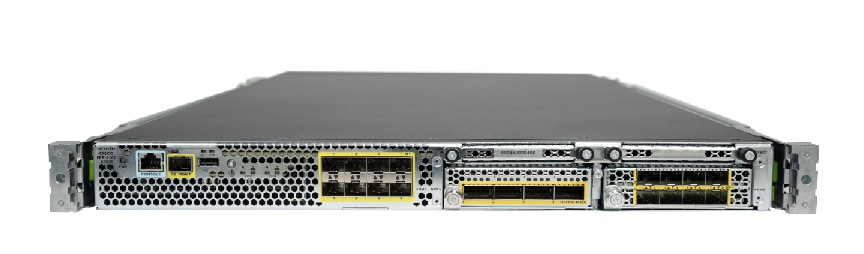
The Cisco Firepower 4100 series security appliance is a standalone modular security services platform. It is capable of running multiple security services simultaneously and so is targeted at the data center as a multiservice platform. The series includes the Firepower 4110, 4120, 4140, and 4150. See Product ID Numbers for a list of the product IDs (PIDs) associated with the 4100 series.
The Firepower 4100 series supports Cisco Secure Firewall Threat Defense, Cisco Secure Firewall eXtensible Operating System (FXOS), and Cisco Secure Firewall ASA software. See Cisco Firepower 4100/9300 FXOS Compatibility, which lists software and hardware compatibility information for the Firepower 4100 series.
 Note |
The Firepower 4100 series security appliance is not supported in Secure Firewall Threat Defense 7.3 and later and Secure Firewall ASA 9.19 and later. |
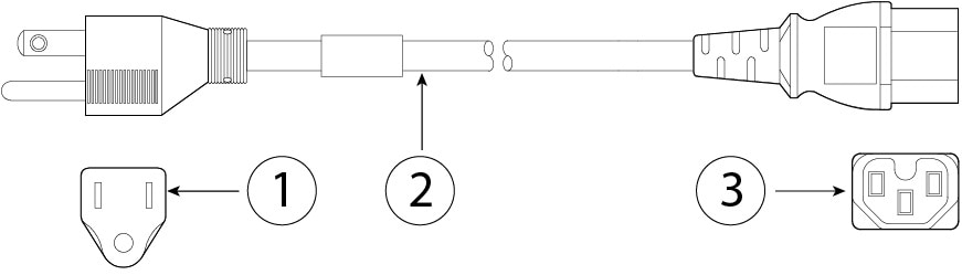
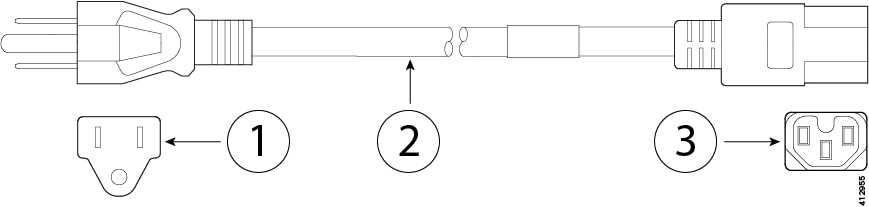
The following figure shows the Firepower 4100 series security appliance.
The following table lists the features for the Firepower 4100 series.
|
Feature |
4110 |
4120 |
4140 |
4150 |
||||||||
|---|---|---|---|---|---|---|---|---|---|---|---|---|
|
Form factor |
1 RU Fits a standard 19-inch (48.3cm) square-hole rack |
|||||||||||
|
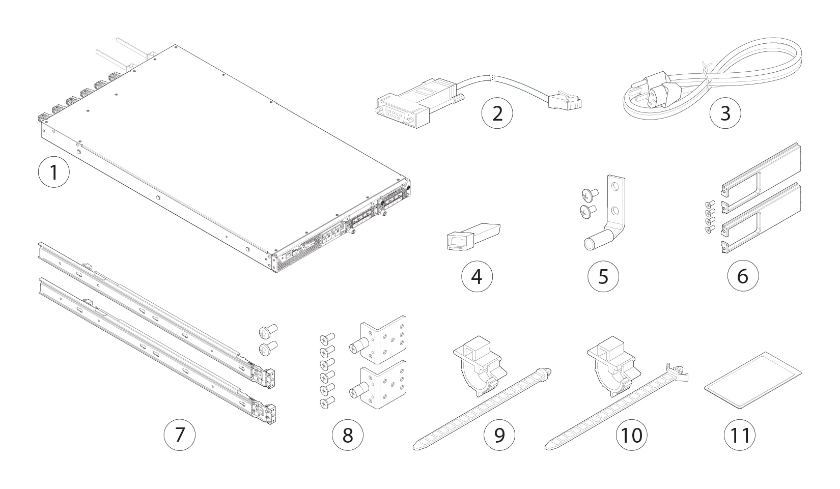
Rack mount |
Slide rails, mount ears, and screws included 4-post Electronic Industries Association (EIA)-310-D rack |
|||||||||||
|
Airflow |
Front to rear Cold aisle to hot aisle |
|||||||||||
|
Processor |
Single 12-core |
Single 18-core |
Single 22-core |
|||||||||
|
Memory |
64-GB DDR4 DRAM |
128-GB DDR4 DRAM |
256-GB DDR4 DRAM |
256-GB DDR4 DRAM |
||||||||
|
Maximum number of interfaces |
24 With two 8-port network modules installed |
|||||||||||
|
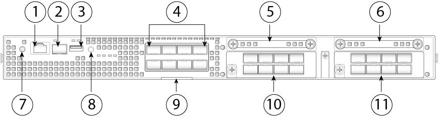
Management port |
One Gigabit Ethernet Supports 1-Gb fiber or copper small form-factor pluggable (SFP) |
|||||||||||
|
Serial port |
One RJ-45 console |
|||||||||||
|
USB port |
One USB 2.0 Type A |
|||||||||||
|
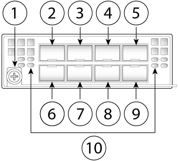
Network ports |
Eight fixed 1-Gb and 10-Gb SFP+ ports (named Ethernet 1/1 through 1/8) |
|||||||||||
|
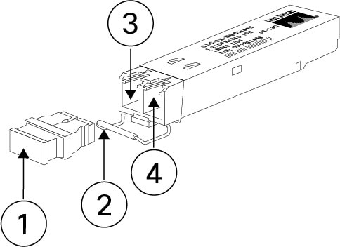
Small form-factor pluggable (SFP) ports |
Eight fixed 1-Gb and 10-Gb SFP+ ports See Supported SFP/SFP+ and QSFP Transceivers for a list of supported transceivers. |
|||||||||||
|
Pullout asset card |
Displays the serial number; on the front panel |
|||||||||||
|
Grounding lug |
On rear panel |
|||||||||||
|
Locator beacon |
On front panel |
|||||||||||
|
Power switch |
On rear panel |
|||||||||||
|
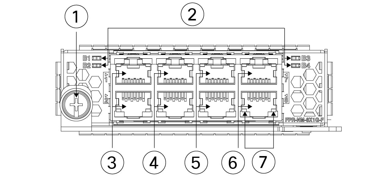
Network modules |
Two network module slots (named network module 2 and network module 3) |
|||||||||||
|
Supported network modules |
|
|||||||||||
|
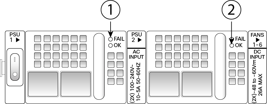
AC power supply |
Two (1+1) power supply module slots Ships with one 400-W AC power supply modules Hot-swappable |
Two (1+1) power supply module slots Ships with two 400-W AC power supply modules Hot-swappable |
||||||||||
|
DC power supply |
Optional |
|||||||||||
|
Redundant power |
1+1 |
|||||||||||
|
Fan |
Six fan module slots 3+1 redundancy Hot-swappable |
|||||||||||
|
Storage |
Two SSD slots Ships with one 200-GB SSD installed in slot 1. Slot 1 is the primary SSD and should always be present. Slot 1 is reserved for the logical device application instance (threat defense or ASA).
|
Two SSD slots Ships with one 400-GB SSD installed in slot 1. Slot 1 is the primary SSD and should always be present. Slot 1 is reserved for the logical device application instance (threat defense or ASA).
|
||||||||||
|
MSP |
Installed in the second SSD slot only |
|||||||||||
|
Security standards certifications |
|
|||||||||||
|
Network Equipment Building Systems (NEBS) certification |
— |
Certified |
— |
— |
||||||||


 Feedback