Cyber Vision New UI

Cisco Cyber Vision New UI

A Cyber Vision New UI is an asset-based user interface that

  • organizes information around assets, which is a clearer representation of physical equipment, instead of discrete components or device entries,

  • aggregates multiple network identities (including interfaces, IP addresses, and MAC addresses) that belong to the same physical equipment, and

  • prioritizes the most relevant information, such as asset name, type, and version, to help users stay focused and reduce clutter.

The New UI significantly improves usability by introducing an asset-centric approach. It simplifies navigation, addresses the complexity issues of the Classic UI, and enhances operational insights and security posture management.

Expanded explanation

The Classic UI focuses on technical entities such as components and devices. Users need to manually define presets, such as baselines or monitoring sets. They often manage separate entries for each network identity, which results in complexity and confusion.

The Cyber Vision New UI connects the physical industrial environment and its digital representation. It visually groups all elements associated with a single physical equipment. Examples include production line equipment or customer installations.

Table 1. Contrast table

Feature

Classic UI

New UI

Entity focus

Components, devices

Assets—representation of physical equipment

Information grouping

Each network identity shown as a separate item

Multiple identities grouped by asset

User effort

Requires manual preset definitions

Provides automatic aggregation to improve clarity

Information display

Shows all details, often overwhelming

Displays only the most relevant attributes of each asset.

Example

  • In the Classic UI, an industrial controller with several MAC and IP addresses appeared as multiple, unrelated items.

  • In the asset-based New UI, all interfaces and addresses for one controller appear under a single, unified asset. Each asset is clearly labeled by name, type, and version.

Assets

An asset is a network entity that

  • serves as a core physical component within an industrial network, such as a programmable logic controller (PLC), a switch, a controller, or a server,

  • may represent one or more modules with distinct identifiers, which may include serial number, reference, or type, even when MAC and IP addresses overlap; and

  • is defined, categorized, and managed according to established rules in Cisco Cyber Vision to ensure effective asset inventory and operations.

Modular assets: If an asset is modular (for example, a chassis with multiple modules), its summary includes module information such as slot, model name, type, firmware version, and serial number. Each module (such as a CPU, communication module, or I/O module) appears as a distinct block within the chassis view.

Asset interfaces

Assets use different network interfaces to communicate within the network, such as MAC addresses, IP addresses, VLAN IDs, or combinations. The system collects interface properties from network traffic and chooses one as the primary interface for visualizations. You can change the primary interface if multiple interfaces exist. The asset list shows both the primary and additional interfaces for each asset.

Asset data management

The table presents the main functions available for managing asset data in the Assets page. It describes the specific capabilities and behavior of each function.

Function

Description

Delete assets

By default, the system deletes assets removed from the production line after 30 days.

You can manually delete assets detected due to misconfiguration. If sensors detect the assets again, the system may re-add them to the inventory.

Search for assets

Enter at least three characters from an asset’s name, IP address, or MAC address in the search bar to quickly locate details.

Export

Export all asset data to a CSV file. The export includes asset IDs so you can distinguish assets with the same name.

Filter asset data

Select Assets and use one of the these methods to manage the asset table:

  • Click Focus to sort the asset table by Default, Network, or Security.

  • Access the table settings menu to show or hide columns as needed.

Vulnerabilities

A vulnerability is a system weakness that

  • enables attackers to gain unauthorized access or perform malicious actions,

  • results from flaws in system design, implementation, or configuration, and

  • requires mitigation through security measures to prevent exploitation.

The system detects vulnerabilities when an asset or component matches a rule in the Knowledge Database. These rules come from CERTs, manufacturers, and partner manufacturers (for example, Schneider or Siemens). Vulnerabilities are identified by correlating Knowledge Database rules with normalized asset and component properties.

The Vulnerabilities page lists all identified vulnerabilities and their details, including the CSRS score, CVSS score, and the number of affected assets.

Vulnerability scores

Vulnerability scores are indicative of the potential risk level and impact associated with specific vulnerabilities. Vulnerability scores include these scoring systems:

Cisco Security Risk Score (CSRS)

The CSRS evaluates vulnerabilities beyond technical severity, focusing on how attackers might exploit them. Scores range from 0 to 100 and are based on factors such as existing vulnerabilities, threat intelligence, and the effectiveness of security controls. This score helps prioritize critical vulnerabilities and allocate resources effectively.

Table 2. CSRS categories:

Score

Vulnerability

67–100

High vulnerability

34–66

Medium severity vulnerability

0–33

Low severity vulnerability

Common Vulnerability Scoring System (CVSS)

The CVSS assigns a score out of 10 based on factors like attack complexity, attack vector, and potential impacts. Security teams use CVSS scores to prioritize severe vulnerabilities and strengthen system security.

Table 3. CVSS categories:

Score

Vulnerability

9–10

Critical vulnerability

7–8.9

High severity vulnerability

4–6.9

Medium severity vulnerability

0.1–3.9

Low severity vulnerability

Acknowledge or revert vulnerability acknowledgements

Mark vulnerabilities as acknowledged, or undo acknowledgement as needed, to manage security alerts effectively.

Use this procedure when you need to acknowledge vulnerabilities affecting assets or revert previously acknowledged vulnerabilities within the Cyber Vision Center. You can acknowledge vulnerabilities and revert acknowledgments from both the Assets and Vulnerabilities dashboards.

Procedure


Step 1

From the main menu, choose Assets.

Step 2

Select an asset.

Step 3

Select the Vulnerabilites tab.

Step 4

Click a CVE ID to view vulnerability details.

Step 5

Enter a comment in the Add/Edit Comment field.

Step 6

To acknowledge the vulnerability, select Acknowledge on this asset. To revert an acknowledgement, select Revert Acknowledgement.


When you acknowledge a vulnerability, the Cyber Vision Center clears the alerts from the Alerts dashboard. When you revert the acknowledgment, the alerts reappear on the Alerts dashboard.

Communication maps

A communication map is a network visualization tool that

  • visually displays communication patterns among industrial assets,

  • enables filtering and grouping of assets by protocol, network, or functional group, and

  • supports investigation by providing details such as observed protocols, data exchange volumes, and source/destination asset information.

This functionality enables operational technology (OT) and information technology (IT) teams to quickly visualize and understand the communication context of industrial assets. It provides a clear visual reference to abnormal communications and potential risks.

Additional reference information

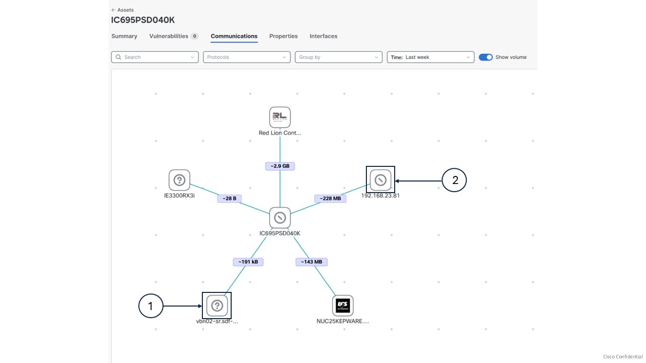
  • Visualization of asset communications: Use the map to view interactions between a selected asset and other internal assets. Vendor icons, IP addresses or MAC addresses, and communication volumes represent these connections. You can identify devices, vendors, or IPs involved in communications quickly.

  • Filter and group communication data:

    • You can filter communications by protocol.

    • You can organize the map by grouping assets according to network (subnet) or functional group. You can expand group nodes to explore individual assets within each group.

    • You can apply a time filter to view communications during specific periods, aiding in the analysis of unusual or suspicious activity.

  • The communication map shows each asset’s vendor icon and name. If a name is not available, it shows the asset’s IP address or MAC address.

    Callouts

    Descriptions

    (1)

    This icon indicates that no vendor information was assigned to the asset.

    (2)

    This icon indicates that the vendor is known, but its icon is unavailable.

Assets and functional group communication maps

Asset and functional group communication maps display the interaction pathways and communication details among assets and within functional groups in the system.
Table 4. Types of communication maps

Type

Description

Asset communication map

From the main menu, choose Assets, select an asset, and then click Communications to access the map.

Select a communication link to view details about the observed protocols, exchange volumes, and asset source or destination information.

Functional group communication map

The Communications page from the main menu displays how accepted functional groups interact with each other.

Click a functional group node to display its internal asset communications."

Note


You need to run asset clustering and accept the functional groups to see the functional group communication maps. See Perform asset clustering.

Asset clustering

An asset cluster is a functional grouping that

  • organizes assets based on their real-world network communication patterns,

  • distinguishes between Operational Technology (OT) and Information Technology (IT) assets for grouping, and

  • is generated automatically through algorithmic analysis.

Asset clustering simplifies asset management by creating functional groups that reflect actual communication behaviors in a network. The system suggests groupings and identifies assets that can transfer between groups. Asset clustering may suggest new functional groups or indicate when significant assets are excluded from a grouping. The asset clustering result remains stable until the communication patterns in the network change.

Asset movement

  • Asset clustering helps to identify assets that can move between functional groups, assets that can move to an ungrouped list, and assets that can move from the ungrouped list into a group.

  • The algorithm recommends which assets to transfer and then provides an updated list of functional groups.

  • If you add or remove a sensor, or delete an asset, the algorithm suggests new functional groups based on the latest data.

Types of functional groups

Asset clustering suggests two types of functional groups to help organize your assets:

  • Communication-based groups: Consist of OT assets that primarily communicate with each other rather than with the broader network. These groups serve as OT process function groups to align with automation stations.

  • Property-based groups: Consist of assets that share common definitions, network attributes, or other properties.

Cluster assets into functional groups

Organize related assets into functional groups for easier management and monitoring.

Use asset clustering to group assets based on function or communication patterns. You can access asset clustering from configuration pages including Functional Group, Sensor Applications, Assets, or from an individual asset's detail page.

Follow these steps to perform asset clustering:

Procedure


Step 1

From the main menu, choose Configuration > Functional Groups.

Step 2

Click Start asset clustering.

The system suggests functional groups in the list.

Step 3

Click the Functional Group name to review group details.

Step 4

Click Map to view asset communications within the group.

Note


The lightning symbol indicates the most significant asset in the group.

Step 5

Click Edit Name to change the Functional Group name.

Step 6

Click Accept to create the functional group.


The assets are clustered into a new functional group.

What to do next

  • Accept or discard the suggested functional groups before you run clustering again.

  • If you click Discard, the system ungroups the recommended assets and includes them in the next clustering run.

Run asset clustering for selected assets

Identify functional groups impacted by a specific set of assets using focused clustering.

Use asset clustering to analyze specific assets and exclude unrelated groups from the results.

Follow these steps to run asset clustering for selected assets:

Procedure


Step 1

From the main menu, choose Assets.

Step 2

Select the assets you want to cluster from the asset list.

Step 3

Click More actions and select Run asset clustering.

Step 4

Click Start.

The asset clustering process uses only the selected assets as its scope.


The system suggests functional groups that are impacted by the selected assets and excludes unrelated groups.

Asset clustering for a selected functional group

Focus asset clustering operations on a specific functional group to optimize asset assignment and management.

This function allows you to perform focused asset clustering for a specific functional group. Use asset clustering to evaluate and optimize how assets are grouped within a selected functional group. This process helps ensure correct grouping, improving management and visibility.

Follow these steps to cluster assets for a functional group:

Before you begin

Confirm you have permission to use asset clustering features.

Procedure


Step 1

From the main menu, choose Assets.

Step 2

Click the group name from the Functional Group column.

Step 3

Click More actions and select Run asset clustering.

Step 4

Click Start.


The system evaluates all assets within the selected functional group. When the evaluation is complete, only the impacted functional groups and corresponding asset information are displayed. The results suggest which assets should remain in the group and which should be removed.

What to do next

Review the suggested changes.

Run asset clustering for a selected sensor

Cluster assets detected by a specific sensor application to improve data organization and analysis.

Perform focused asset clustering on assets associated with a particular sensor to ensure asset groupings are up to date.

Follow these steps to run asset clustering for a selected sensor:

Procedure


Step 1

From the main menu, choose Configuration > Sensor Applications.

Step 2

Check the checkboxes for the sensor applications.

Step 3

Click Run asset clustering.

Step 4

Click Start.


The system identifies and clusters assets detected by the selected sensor.

What to do next

Review the asset clustering results after the process completes. If needed, repeat the procedure for other sensors.

Asset clustering for individual assets

Group similar assets by running the asset clustering function for a selected asset.

Use this function to perform focused clustering on a single asset. This helps you analyze relationships and patterns among assets related to the selected asset. It provides insights specific to that asset.

Follow these steps to cluster an individual asset:

Procedure


Step 1

From the main menu, choose Assets.

Step 2

Click the asset name from the Name column.

Step 3

Click Functional group actions and select Run asset clustering.

Step 4

Click Start.


The system clusters the individual asset, providing a group of similar assets for further analysis.

What to do next

Review the asset clustering results to identify patterns among the grouped assets.

Lock Group

When you lock the group, it stays out of asset clustering. While it's locked, no assets get added or removed during asset clustering.

Procedure


Step 1

From the main menu, choose Assets.

Step 2

Click the group name in the Functional Group column.

The View Functional Group panel appears.

Step 3

Click the More actions drop-down arrow.

Step 4

Click Lock Group from the drop-down list.

The Lock Group pop-up appears.

Step 5

Click Lock.


Move Asset from One Group to Another

You can adjust your functional group by moving assets between groups, even if the algorithm cannot add a specific asset to your group.

Procedure


Step 1

From the main menu, choose Assets.

Step 2

Check the checkbox next to the assets.

Step 3

Click the More actions drop-down arrow.

Step 4

Click Add selected to group from the drop-down list.

The Add Selected To Group panel appears.

Step 5

Click the Functional Group drop-down arrow.

Step 6

Choose the group from the drop-down list.

Step 7

Click Add.

The Add Selected to Group warning appears.

Step 8

Click Add.

Note


After you move assets from one group to another, the system deletes any group that is left with a single asset automatically.

Note


You can also move an asset to another group from its individual detail page.


Delete the Functional Group

Procedure


Step 1

From the main menu, choose Assets.

Step 2

Click the group name from the Functional Group column.

The View Functional Group side panel appears.

Step 3

Click Delete group.

The Delete Group window appears.

Step 4

Click Delete.


Remove Asset from Functional Group

To remove asset from functional group:

Procedure


Step 1

From the main menu, choose Assets.

Step 2

Check the checkbox to select the asset name in the Name column.

Step 3

Click the More actions drop-down arrow.

Note


Accept or discard the suggested functional groups to access More actions field.

Step 4

Click Remove asset from the group from the drop-down list.

The Remove From Group pop-up appears with a note.

Step 5

Click Remove.


Alerts

Alerts are system-generated notifications that

  • indicate significant activity or irregularities detected within an industrial network,

  • categorize information based on type, associated data, and network components, and

  • provide warnings to help with security monitoring and response.

An alert is a notification that triggers when a user-defined rule’s condition is met. You can configure Cyber Vision to forward alerts through Syslog when alerts are raised, cleared, or when their status changes. For details about this configuration, see Enable or disable syslog notifications for an alert type.

You can acknowledge vulnerabilities on assets to clear corresponding alerts from the dashboard or revert acknowledgments to restore alerts.

Additional reference information

  • Active alerts: Display all current alerts. An alert remains active while the underlying issue still exists on the affected asset.

  • Cleared alerts: When an issue is resolved, the alert appears in the Cleared tab, indicating that it no longer impacts the asset. The system retains cleared alerts for up to 14 days before purging them.

  • Default alert types and associated rules:

    • Severe vulnerabilities in monitored entities: Monitors specified assets and raises alerts for high-severity vulnerabilities.

      The default rule is Default_OH_Global. For this alert type, you can edit, duplicate, delete, or create new rules.

    • Prohibited vendors: Triggers alerts for assets linked to prohibited vendors.

      The default rule is Prohibited_list. For this alert type, you can only edit rules; you cannot duplicate, delete, or add rules.

Alert details are as follows:

Table 5. Alert details

Name

Description

Alert Type

Types include Severe vulnerabilities in monitored entities, and Prohibited Vendors.

Trigger

Values based on alert types such as vulnerabilities or vendor names.

Instances

Number of assets impacted by the defined alert rules.

Severity

Severity levels (Critical, High, Medium, or Low).

Triggered By

Alert categories.

Last Detected

Shows last detected date and time.

Alert type management options and permitted alert rule actions

Manage the alerts that are raised for monitored entities and prohibited vendors in your system.

For each alert type, the configuration interface (Configuration > Alerts) allows control of the alert’s state (Pause or Resume) and management of the associated alert rules that determine when alerts are raised. Use these management actions to maintain security awareness for your organization.

Table 6. Permitted alert rule actions for each alert type

Alert Type

Permitted alert rule actions

Severe vulnerabilities in monitored entities

Create, edit, duplicate, or delete alert rules

Prohibited vendors

Edit alert rules only


Note


  • When you pause an alert type, new alerts for its associated rules temporarily stop. This does not affect existing alerts.

  • When you resume a paused alert type, new alert notifications for its rules are re-enabled.

  • Rule management permissions depend on the alert type:

    • For Severe vulnerabilities in monitored entities, all rule management actions are allowed.

    • For Prohibited vendors, only rule editing is permitted.


Create alert rules

Add alert rules to monitor asset vulnerabilities and receive timely notifications in the Alerts dashboard.

Alert rules in the Severe vulnerabilities in monitored entities alert type let you track severe vulnerabilities in assets. When a vulnerability matches a rule, the dashboard shows an alert.

Before you begin

  • You cannot create alert rules for the Prohibited Vendors alert type.

  • The system displays only default alert rules.

Procedure


Step 1

From the main menu, choose Configuration > Alerts.

Step 2

Select the Severe vulnerabilities in monitored entities alert type.

Step 3

Click Create new rule.

Step 4

Add an Alert Rule Name, then select the Severity and Entity type.

Step 5

On the Entity selection page, select either an organization hierarchy level or functional groups.

  • If selecting assets based on functional groups, check Include Ungrouped assets to include assets not in any functional group.

  • If selecting assets based on organization hierarchy levels, check Assets seen by Unknown data sources to include unidentified or unmapped assets.

Note


The available Entity selection options depend on the Entity type you chose in the Rule name and entity type step.

Step 6

In the Scoring system and threshold tab, select one scoring system:

  • For Cisco Security Risk Score, enter a threshold number between 34 and 100.

  • For CVSS, enter a threshold number between 7 and 10.

Note


Cisco Security Risk Score is the default, but you can select CVSS.

Step 7

Review your selections in the Summary and click Save.


The new alert rule appears on the Configuration > Alerts > Severe vulnerabilities in monitored entities page. The system generates alerts when asset vulnerabilities match the new rule.

What to do next

  • Regularly review the Configuration > Alerts page to manage and update alert rules as needed.

  • To manage alert rules, navigate to Configuration > Alerts, select an alert type, and choose edit, duplicate, or delete actions.

Syslog notification details for various alert types

You receive syslog notifications on the configured syslog server when the system raises, clears, or changes the status of an alert.

Syslog notifications details

The syslog message contains these details that apply to all alert rules:

  • CEF:0

  • vendor: cisco

  • product: Cyber Vision

  • version: 2.0

  • event_class_id: alert_raised OR alert_cleared

  • event_name: alert type name

  • severity id: 2 (The value changes based on the severity of the alert rule.)

  • cat=alert category

  • SCVAuthorId=user uuid (optional): This field is populated only if a user manually acknowledged an alert; it is empty when the system cleared the alert.

  • alertRuleId=alert rule uuid

  • alertId=alert uuid

  • msg=The value changes based on the alert type and the event_class_id.

  • assetId

  • assetName

  • assetFunctionalGroupId (empty when ungrouped)

  • center-id=uuid of center

  • sensorNames

The syslog message includes these details for Severe vulnerabilities in monitored entities:

  • vulnNumber: for example, CVE-2023-10025.

  • vulnName

  • vulnCVSSscore

  • vulnCSRSscore

When the alert involves Prohibited Vendors, the syslog message lists the "vendorName" field.

Enable or disable syslog notifications for alert types

You can manage whether the Cyber Vision Center sends syslog notifications for alerts of specific alert types to your configured syslog server.

Follow these steps to enable or disable syslog notifications for an alert type:

Before you begin

  • Ensure you have administrator access to Cyber Vision Center.

  • Confirm that a syslog server is configured. See Configure syslog.

Procedure


Step 1

From the Cyber Vision New UI, choose Configuration > Alerts.

Step 2

Select an alert type.

Step 3

Enable or disable Syslog Notification.


When you enable syslog notifications in the Cyber Vision Center, you receive syslog messages on the configured syslog server whenever the system raises (or unmutes), clears, or mutes an alert.

Organization hierarchies

An organization hierarchy is a structural model that

  • organizes and groups assets, sensors, and data sources within Cisco Cyber Vision Center,

  • uses a system-defined Global level as the root, and

  • supports up to five nested sub-levels with configurable options for adding, editing, or deleting levels.

A level is a node in the hierarchy representing a logical grouping, such as a site or zone.

Additional reference information

This hierarchical structure enables users to manage industrial network assets efficiently, customize monitoring views, and streamline oversight.

Key points about organization hierarchies in Cyber Vision Center:

  • Each node in the hierarchy is called a level.

  • The topmost level is the Global level, which is system-defined.

  • The system supports nesting up to five sub-levels; beyond this limit, no additional levels can be added.

  • You can add, edit, or delete levels in the hierarchy through Configuration > Organization Hierarchy. These restrictions apply:

    • The Global level cannot be deleted.

    • Levels with child levels or assigned entities (such as sensors or PCAPs) cannot be deleted.

Filter views in Cyber Vision New UI

Narrow the information displayed in Cyber Vision New UI by applying filters to the Dashboard, Alerts, Assets, Vulnerabilities, and Communications pages.

Use filters to focus on specific assets, network segments, or alerts in Cyber Vision. Filtering does not affect Configuration pages.

Follow these steps to filter data in Cyber Vision:

Procedure


Step 1

From the main menu, choose Organization.

Step 2

Select either Sensors or Networks.

Note


The Sensors tab is selected by default.

  • To select all sensors or networks at a hierarchy level, select that level.

  • To choose specific sensors or networks from a selected hierarchy level, open the organization drawer again, open Sensor selection or Network selection, select the needed items, and click Apply.

  • Use the search box to find sensors or networks by name.

Step 3

To clear the selected sensors or networks and return to the complete organization hierarchy selection, open the Organization Hierarchy drawer again and click the Reset selection icon.

Step 4

To edit the sensor or network selection for the selected organization hierarchy only, open the Organization Hierarchy drawer again and click the Edit selection icon.

Step 5

To refine the filter, click Edit on the active view bar.

Step 6

Use the Select buttons to add filters as needed.

Step 7

Click Apply to update or Reset to clear the filters.


The views show only data that matches your filter criteria.

What to do next

Review the filtered data on the Dashboard, Alerts, Assets, Vulnerabilities, or Communications pages as needed.

Network definitions

A network definition is a configuration element in Cyber Vision that

  • specifies which networks (IP ranges and VLANs) should be monitored,

  • allows classification of internal IT and OT assets to improve asset inventory accuracy, and

  • enables exclusion or grouping of assets for focused security assessments.

Additional reference information

  • Cyber Vision preconfigures network definitions with the default RFC1918 addresses 10.0.0.0/8, 172.16.0.0/12, and 192.168.0.0/16.

  • Cyber Vision supports three principal network types:

    • OT Internal (PLCs, HMIs)

    • IT Internal (laptops, IT devices)

    • External (assets excluded from inventory)

  • Network administrators choose network types and validate IP ranges to avoid duplication.

  • In the Classic UI, you can create new network definitions. In the New UI, you can only view and assign existing definitions.

Example

  • OT Internal networks may include subnets dedicated to industrial controllers.

  • IT Internal networks may include office workstation IP ranges.

  • External networks encompass public IP addresses or networks outside the organizational boundary.

Counter example:

  • Networks not defined are not monitored and do not appear in the asset inventory.

  • External networks are not included in asset classification.

Assign a network to an organization hierarchy

Assign a specific network to a designated level within the organization hierarchy. This action aligns management access and policy controls with the organizational structure.

Perform this task when you need to organize network resources, apply hierarchical policies, or update the organizational assignment for the network.

Follow these steps to assign a network to an organization hierarchy:

Before you begin

You must have Network Definition permission with read/write access.

Procedure


Step 1

From the main menu, choose Configuration > Network Definition.

Step 2

Locate the network you want to assign and click Assign.

Step 3

Select the appropriate organization hierarchy level.

Step 4

Click Assign to complete the assignment.


The selected network is now associated with the specified level in the organization hierarchy.

Pcap files

A Packet Capture (PCAP) file is a file format that:

  • records raw network traffic data as captured from a network interface,

  • preserves the exact communication packets exchanged between various assets, and

  • enables network analysis and asset identification when imported into Cyber Vision Center.

Additional reference information:

To analyze traffic from your OT network, upload PCAP files to Cyber Vision. Use the Classic UI to upload PCAP files. For more details, see PCAP Upload.

When you import the file, Cyber Vision creates and identifies assets and associates them with their properties and communication patterns. You can then view these assets throughout the system, including on the main dashboard.

Assign multiple PCAP files to an organization hierarchy

Before you begin

  • Confirm you have appropriate permissions to assign PCAP files.

  • Ensure the required PCAP files have already been uploaded.

Assign multiple packet capture (PCAP) files to an organization hierarchy to enable automated asset creation in Cisco Cyber Vision.

Use this task to organize and manage multiple PCAP files for asset management within an organization hierarchy.

Follow these steps to assign multiple PCAP files to the organization hierarchy:

Procedure


Step 1

From the main menu, choose Configuration > PCAPs.

Step 2

Select the PCAP files you want to assign to an organization hierarchy.

Step 3

Click Assign Selected to Organization Hierarchy.

Step 4

Choose the appropriate organization hierarchy.

Step 5

Click Assign.


The selected PCAP files are assigned to the chosen organization hierarchy, automatically initiating asset creation in Cisco Cyber Vision.

Each PCAP initiates asset creation in Cisco Cyber Vision.

Sensor applications

A sensor application is an embedded software component that

  • runs on Cisco networking devices or runs as a standalone system,

  • captures industrial network traffic and performs deep packet inspection to extract relevant information, and

  • securely transmits metadata to the center for storage and analytics.

Health Status: Health status describes the operational and enrollment state of a sensor. Key states are:

  • New: The sensor’s first status after detection by the Center; it is requesting an IP address from the DHCP server.

  • Request pending: The sensor has requested a security certificate from the Center and is awaiting enrollment authorization.

  • Authorized: The sensor has just been authorized by an administrator or product user and will soon transition to "Enrolled."

  • Enrolled: The sensor has completed enrollment, possesses a certificate and private key, and is actively connected to the Center.

  • Disconnected: The sensor was previously enrolled but is not currently connected to the Center. Possible reasons include device shutdown, network disruptions, or sensor issues.

Processing Status: Processing status reflects how the sensor processes and communicates data with the Center. Main statuses include:

  • Disconnected: The sensor is enrolled but not currently connected to the Center.

  • Not enrolled: The sensor is not yet enrolled; typically paired with the “New” or “Request Pending” health status.

  • Normally processing: The sensor is connected and actively sending data to the Center for analysis.

  • Waiting for data: The Center has processed all received data and is awaiting new data from the sensor.

  • Pending data: The sensor is attempting to send data, but the Center is busy processing other incoming data.

Additional reference information

Sensor applications use Cisco’s IOx platform to integrate into existing Cisco routers, switches, or purpose-built appliances. Installed sensors appear under the Configuration > Sensor Applications section of the Cyber Vision New UI. This section provides an overview of each sensor’s network device, health, processing status, and organizational hierarchy context

Assign sensors to the Organization Hierarchy

Assign one or more sensors to an Organization Hierarchy to enable asset creation within Cisco Cyber Vision.

Use this task to map sensors in your environment to a defined organization hierarchy. Assignment enables Cisco Cyber Vision to organize asset data and operational context based on organization hierarchy.

Follow these steps to assign sensors to the organization hierarchy:

Procedure


Step 1

From the main menu, choose Configuration > Sensor Applications.

Step 2

To assign a single sensor, locate the sensor and click Assign.

Step 3

To assign multiple sensors, select the checkboxes for each sensor and click Assign Selected to Organization Hierarchy.

Step 4

Select the organization hierarchy.

Step 5

Click Assign to confirm.


Your selected sensors are assigned to the organization hierarchy. Each assigned sensor is responsible for asset creation in Cisco Cyber Vision.

Use Cases

Review All PLC and SCADA Data Servers in the Paint Shop

Procedure


Step 1

Organize Network in the Classic UI.

  1. Define a network within the Network Organization section.

  2. Ensure that the network includes the subnet for both the PLC and SCADA network.

    For example, use the subnet 192.168.41.0/24.

Step 2

From the main menu, choose Assets.

Step 3

Click the filter icon at the top-right corner of the table.

Step 4

To filter the asset list, search for the network name in the Network column.

Review the different assets in the paint shop.

Note


Users cannot edit the network definition information in the New UI.

Step 5

To see the details of the assets, click the asset name.


Analyze and Acknowledge All Vulnerabilities with a CVSS Score Above Nine

Users can review vulnerabilities through either the vulnerability list for each asset or the comprehensive list of vulnerabilities. Both lists include a filter to display specific CVSS scores.

Procedure


Step 1

From the main menu, choose Assets.

Step 2

Click the asset Name.

Step 3

Click Vulnerabilities.

Step 4

Click the filter icon at the top right corner of the table.

Step 5

Click the drop-down arrow of the CVSS Score column.

Step 6

Select Critical from the drop-down list.

This will show vulnerabilities with a CVSS score between 9.0 and 10.

Step 7

To acknowledge the vulnerability, click Acknowledge.

Acknowledging the vulnerability will hide it from dashboard counters, clear alerts, and make filtering easier.