Configure Cisco Cyber Vision

Network Organization

Network Organization page allows you to define the subnetworks inside the industrial network by setting up IP address ranges and declaring whether networks are internal or external. To access the Network Organization page, choose Admin > Network Organization from the main menu.

In Cisco Cyber Vision, all private IP addresses are classified as OT internal. They appear under the IP Address / Subnet column on the Network Organization page.

Every other IP address is considered as external, except for:

  • Broadcast IPv4: 255.255.255.255

  • IPv4 and IPv6 zero: 0.0.0.0 et 0:0:0:0:0:0:0:0

  • Loopback IPv4 and IPv6: 127.0.0.1 and ::1

  • Link Lock Multicast IPv4 and IPv6: 224.0.0.0/8 and ff00::/8

If you want to declare a public IP address as internal, you must add an exception by changing their network type.

Declaring a subnetwork as OT internal is useful in case public IP addresses are used in a private network of an industrial site. Conversely, declaring a set of IP addresses as external will exclude their flows from the database, and exclude their devices from the license device count and the risk score.

Overall, defining subnetworks in Cisco Cyber Vision is useful for several reasons:

  • It allows you to choose afterwards how related flows should be stored through the Ingestion configuration page. Excluding unnecessary flows will have positive impact on performances.

  • It will impact devices' risk scores, since a private network is considered as safer than an external one.

  • Cisco Cyber Vision's license will be more accurate, because devices from an external network will be excluded from the licensing device count.

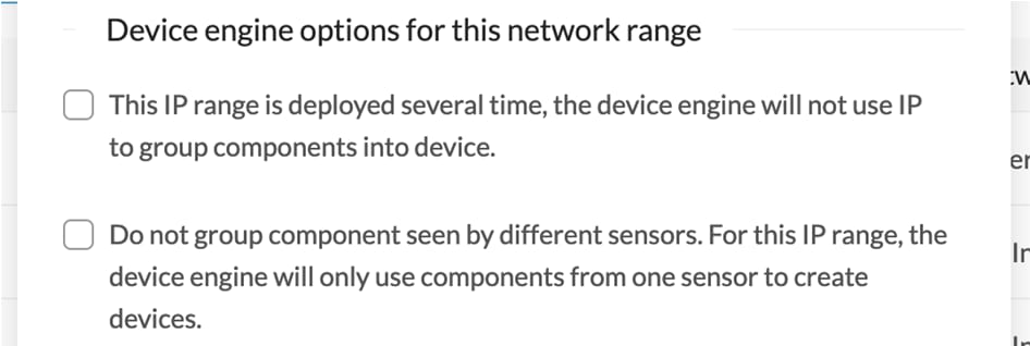
By default, Cisco Cyber Vision groups identical IP addresses detected inside the industrial network into a single device, because in most cases these belong to several components of a device. However, it can happen that the same IP address is used by several devices. In this case, you can choose to select the first option when declaring a subnetwork to prevent duplicate IP addresses from grouping within this subnetwork.

The second option is to be used when components with the same IP address are found by different sensors. This happens when same addressing parameters are used on several subnetworks, for example in case of identical production lines. By using this option, components detected by different sensors will not be aggregated into a single device.

IP ranges can be organized into groups which subranges can be defined like in the example below:

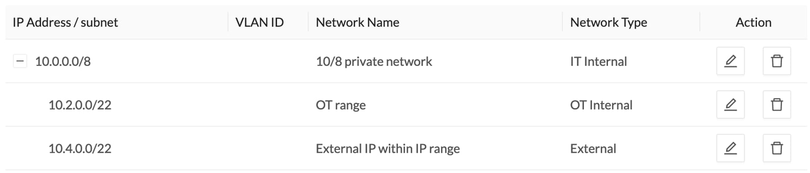
Here, the user specified that the IP range 10.2.0.0/22 is OT internal and that 10.4.0.0/22 is external.

Thus, flow storage can be specificly set in the Ingestion Configuration for the IP range set here as OT internal, whereas flows and devices from the IP range set as external will be excluded from the database and the license device count and risk score.


Note


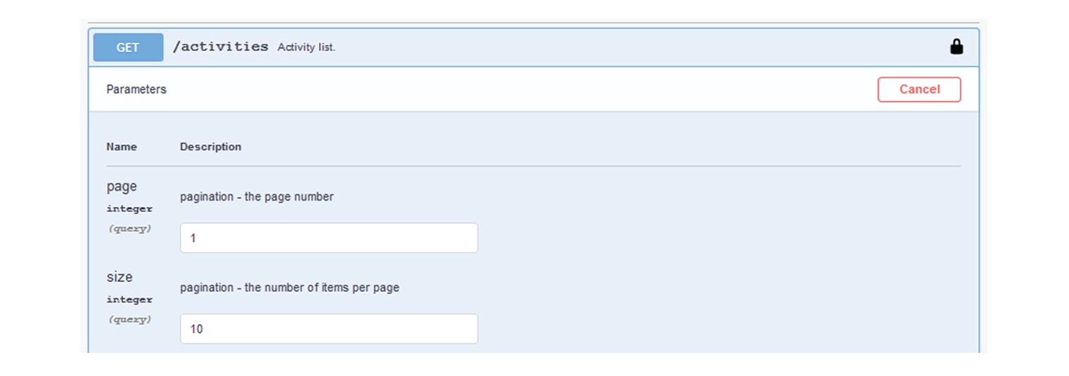
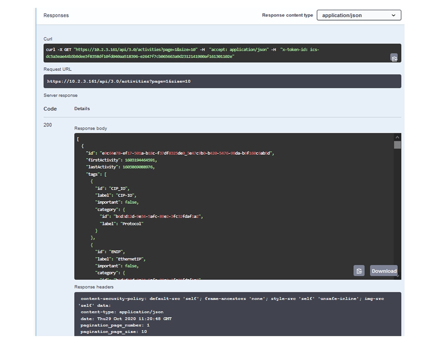
It is also possible to organize subnetworks through the API.


Define a Subnetwork

To define a subnetwork:

Procedure


Step 1

From the main menu, choose Admin > Network Organization.

Step 2

Click Add a network.

The ADD A NEW NETWORK pops-up appears.

Step 3

Enter an IP address range and its subnet in the IP address/subnet field.

Step 4

(Optional) Enter the VLAN ID.

This will allow you to create overlapping networks.

Step 5

Enter the Network name.

Step 6

Click the dropdown arrow of the Network Type.

Step 7

Select the network type from the dropdown list, such as OT Internal, IT Internal, or External.

Note


Setting the network type can impact Cisco Cyber Vision's performances by setting flow storage, device risk scores, and the license's device count.

Step 8

Check the Use a device engine option for this network range checkbox.

  1. If applicable, select the radio button for the first option.

    Note


    Enable this option if several devices share the same IP across the monitored network.

    Components will not be grouped by IP.

  1. If applicable, select the radio button for the second option.

    Note


    Enable this option in case same addressing parameters are used within different subnetworks, for example, in identical production lines.

    For that particular network range, the system will not aggregate components with the same IPs detected by sensors monitoring other subnetworks. The system will aggregate the components into devices when monitored subnetworks use the same IP ranges for several machines or production lines.

    In this case, for a specific IP range, a component with an IP of that range seen by a sensor will be grouped with a component with the same IP only if both components are detected by the same sensor.

Step 9

Click Add a network.


API Token

Cisco Cyber Vision provides a REST API. To use it you first need to create a token through the API administration page.

A token is a random password which authenticates a request to Cisco Cyber Vision to access or even modify the data in the Center through the REST API. For instance, you can request the latest 10 components detected on Cisco Cyber Vision or create new references. Requests can be used by external applications like a SOC solution.


Note


Best practice: create one token per application so you can remove or expire accesses separately.

To create API token, follow these steps:

  1. From the main menu, choose Admin > API > Token.

  2. Click + New token.

    The Token window appears.

  3. Enter a name.

  4. Use the Status toggle button to disable authorization for the token if you plan to use it later and want to prevent access until then.

  5. Set an Expiration time.

  6. Click Create.

    After the token creation, token appears in the list available on the API page.

  7. Click Show to view the token.

  8. Click copy icon to copy it.

For more information about the REST API refer to the REST API user documentation available on cisco.com.

API Documentation

This page is a simplified API development feature. It contains an advanced API documentation with a list of all possible routes that can be used and, as you scroll down the page to Models, a list of possible data responses (data type, code values and meaning).

In addition to information research, this page allows you to perform basic tests and call the API by sending requests such as GET, DELETE and POST. You will get real results from the Center dataset. Specifications about routes are available such as the route's structure, and parameters and arguments that can be set. An URL is generated and curl can be used in a terminal as it is.

However, for an advanced use, you must create an application that will send requests to the API (refer to the REST API documentation).


Important


All routes other than GET will modify data on the Center. As some actions cannot be reversed, use DELETE, PATCH, POST, PUT with caution.

Routes are classified by 's elements type (activities, baselines, components, flows, groups, etc.).

The category "Groups" containing all possible group routes:

To authorize API communications:

Procedure


Step 1

From the main page, choose Admin > API .

Step 2

Click Token to create and/or copy a token.

Step 3

Click Documentation.

Step 4

Click Authorize.

The Available authorizations panel appear.

Step 5

Paste the token in Value field..

Step 6

Click Authorize.

Step 7

Click Close.

Close lockers displays. They indicate that routes are secured and authorization to use them is up.

To use a route:

Step 8

Click a route to deploy it.

In the example, we choose Get activity list.

Step 9

Click Try it out.

Step 10

You can set some Parameters.

In the example, we set page to 1 and size to 10.

Step 11

Click Execute.

Note

 
You can only execute one route at a time.

A loading icon appears for a few moments. Responses display with curl, Request URL and the server response that you can copy or even download.

Step 12

When you are finished, click the Authorize button.

Step 13

Log out to clear the token variable, and click Close.


Active Discovery Policies

Active Discovery is used to allow a sensor to send packets to the network to discover previously unseen devices and gather additional properties for known devices.

Active Discovery operates in Broadcast and Unicast, and responses received will be analyzed by Cisco Cyber Vision.

An Active Discovery policy is a list of settings which define protocols and their parameters that will be used to scan the industrial network. The policy will be used in a preset and be applied on a list of sensors and components.

To acces the Active Discovery policies page, choose Admin > Active Discovery > Policies from the main menu.

For more information, refer to the Active Discovery Configuration Guide.

LDAP

Cisco Cyber Vision can delegate user authentication to external services that use LDAP (Lightweight Directory Access Protocol), specifically Microsoft Active Directory and AD LDS services.

To configure an LDAP connection, from the main menu, choose Admin > External Authentication > LDAP.

Configuring LDAP:

LDAP integration can be done through an unencrypted connection, or in a secure way by using certificates for encryption, depending on installation compatibility.

Mapping Cisco Cyber Vision roles with Microsoft Active Directory groups:

User groups available in the external directory can be mapped to Cisco Cyber Vision Product, Operator and Auditor user roles or custom roles. Refer to Role Management to create custom roles.

Because the Admin user role is exclusively reserved for Cisco Cyber Vision intersnal usage, it cannot be mapped to any external users and thus is not proposed in LDAP settings.

Testing LDAP connection:

After setting up LDAP, the connection between the Cisco Cyber Vision Center and the external directory is to be tested. On the LDAP test connection window, you will use a user login and a password set in the external directory. The Center will attempt to authenticate on the directory server with these credentials. In return, you will get either a successful authentication, or a failed one with an error message.

Login in Cisco Cyber Vision:

When logging into Cisco Cyber Vision, the login format used will determine the base (i.e. internal or external) to be queried:

  • If you use an email, the Cisco Cyber Vision database is queried.

  • If you use the Active Directory format <domain_name>\<user_name> (e.g. cisco\john_doe), then the external directory is used to authenticate users.

Configure LDAP

This taskflow takes you through configuring LDAP in Cisco Cyber Vision using an unencrypted connection or a secure connection.

You can establish two types of secure connections:
  • For a highly secure connection, choose the LDAP over TLS/SSL setting to use a CA-signed certificate with a trust chain. You must upload the certificate into the Center during the configuration task.

  • For internal applications where trust is not a primary concern, choose the Use self signed certificate setting. The Center automatically generates and uses self-signed certificates for this connection type. You don't need to provide a self-signed certificate.

Procedure


Step 1

From the main menu, choose Admin > External Authentication > LDAP.

Step 2

Click New Settings.

Step 3

In the Settings tab,

  1. Choose LDAP over TLS/SSL or Use self signed certificate, or neither.

  2. Enter Primary Server Address.

  3. Enter Primary Server Port.

  4. (Optional) Enter Secondary Server Address.

  5. (Optional) Enter Secondary Server Port.

  6. In the Base DN field, enter the distinguished name by which LDAP API recognize this LDAP connection.

  7. (Optional) Check the Modify search filter check box. Then, in the Search Filter field, enter a search filter.

    The default search filter retrieves a user's groups by binding with the user's credentials. You can also modify the filter to target a different attribute, and the specified attribute's value is then used for both group search and binding (login).

    In the Search Filter field, you must include the $user variable. The variable is replaced with the username entered when logging in.

  8. In the Server Response Time field, enter a timeout value, in seconds, after which the Center attempts to connect to the secondary server instead of the primary server.

  9. (Optional) Check the Use Service Account check box. When an LDAP user doesn't have access to their own group, a service account is used. When this setting is enabled, the service account is used to search for and retrieve the user's groups.

    1. Enter a service account username.

    2. Enter a service account password.

  10. If you chose LDAP over TLS/SSL in Step a, a certificate upload field is displayed. Upload or drag-and-drop a PEM file, root or chain certificate.

    The uploaded certificate is displayed at the bottom of the settings page.

Step 4

In the Role Mapping tab,

  1. Map at least one role, default (Product, Operator, or Auditor) or custom, with an Active Directory group. You can create custom roles in the Custom roles area.

    Note


    Enter the exact group names as configured in the remote directory for successful retrieval and mapping to user roles.

    The Admin role is not listed as a default role because it is reserved for Cisco Cyber Vision internal usage and cannot be mapped to external users.

Step 5

Click OK.

Step 6

Click Test connection.

Step 7

Enter the user credentials to test the connection between Cisco Cyber Vision and Active Directory.

Note


For LDAP, the supported username format is <domain_name>\<user_name> (For example, cisco\john_doe).

For LDS, the supported username formats are:

  • <user_name> (For example, john_doe).

  • <email-address> (For example, john@example.com)

Step 8

Click OK.


You can also test the connection by logging out of Cisco Cyber Vision and logging in with different mapped user credentials. The Center menu changes according to the permissions granted to the user.

Single Sign-On for Cisco Cyber Vision Center

A Single Sign-On (SSO) is an authentication process that:

  • allows you to access multiple applications with one set of login credentials

  • reduces the need for multiple logins and password management, and

  • enhances security by centralizing authentication.

Central authentication and authorization

Central authentication and authorization are a security mechanism that uses a Central identity provider (IdP) to manage user credentials and access permissions across multiple platforms. This approach consolidates authentication strategies into a streamlined process, enhancing efficiency and security.

Federated service provider applications

The applications you set up for SSO are known as federated service provider applications.

Unified access for you

With SSO, you can log in just once to access all the service provider applications you are authorized to use without needing to re-enter credentials.

SAML single sign-on

Security Assertion Markup Language (SAML) is a security protocol that:

  • allows users to authenticate once and gain access to multiple applications,

  • uses identity providers (Idp) for authentication and authorization, and

  • bypasses the need for login credentials for each service.

After successful authentication by the IdP, SSO users return to the Cisco Cyber Vision Center and log in. The browser handles communication between the Cisco Cyber Vision Center and the IdP, so the Cisco Cyber Vision Center does not need a direct network connection to the IdP.

SSO provider support

The Cisco Cyber Vision Center supports SSO with any SSO provider that uses the Security Assertion Markup Language (SAML) 2.0 standard for authentication and authorization.


Note


The Cisco Cyber Vision Center does not sign SAML authentication requests. If the IdP requires signed authentication requests, SSO fails on the Cisco Cyber Vision Center.


SSO providers supported by the Cisco Cyber Vision Center

  • Azure

  • Cisco Duo

SSO guidelines for the Cisco Cyber Vision Center

Prerequisites

Only Admin users authenticated internally or through LDAP or RADIUS are authorized to configure SSO.

Limitations:

  • No IdP-Initiated SSO: The Cisco Cyber Vision Center does not support SSO initiated from the IdP.

  • No CAC Credentials: The Cisco Cyber Vision Center does not support logging in with CAC credentials for SSO accounts.

  • No CC Mode: Do not configure SSO in deployments using CC mode.

Single SSO Provider Support:

The Cisco Cyber Vision Center supports only one SSO provider at a time, such as Azure or Duo.

SSO in high availability configurations:

  • Separate Configuration: Configure SSO separately for each member of a high-availability pair, as they are not synchronized.

  • Same IdP Requirement: Both members of the high availability pair must use the same IdP. You configure a service provider application at the IdP for each the Cisco Cyber Vision Center.

Multi-tenancy and SSO:

  • Global Domain Scope:

    • In multi-tenancy setups, you apply the SSO configuration at the global domain level. This applies to the global domain and all subdomains.

Logging SSO activities:

Audit Logs: The Cisco Cyber Vision Center logs SSO activities, such as login and logout events, in the audit log. Each entry specifies 'Login' or 'Logout' in the Subsystem field.

Single Sign-On user accounts

A single sign-on (SSO) user account allows users to access multiple applications, systems, or services using one set of login credentials, such as a username and password. A central identity provider (IdP) handles the authentication, simplifying the user experience by removing the need for separate logins for each system.

Role of the Identity Provider (IdP)

The identity provider (IdP) manages users and groups or imports them from other applications like Active Directory, RADIUS, or LDAP. It establishes most account details for SSO users, including usernames and passwords.

SSO accounts on the Cisco Cyber Vision Center

SSO accounts appear on the Cisco Cyber Vision Center users page only after the user successfully logs in for the first time.

Email address requirement

Users for single sign-on (SSO) accounts and the NameID attribute sent by the identity provider (IdP) during SAML login must be valid email addresses. Many IdPs automatically use the username of the user attempting to log in as the NameID attribute. Confirm this behavior when configuring your IdP and creating user accounts for SSO access to the Cisco Cyber Vision Center.

Configurable account characteristics

You can configure these characteristics for SSO users from the Cisco Cyber Vision Center web interface:

  • Real name

  • Exempt from browser session timeout

User role mapping for SSO users

The Cyber Vision Center assigns the Security Analyst (Read Only) role to all SSO users by default. You can override the default role for specific users or groups using user role mapping.

At the Cyber Vision Center, you can configure role mapping based on either group permissions or individual user permissions.

  • Test the SSO configuration.

  • Define SSO user roles.

Coordination with the IdP

  • Role assignment: Setting up user roles at the Cyber Vision Center and coordinating them with your SSO IdP application settings. Assign roles either to individual users or to groups defined in the IdP.

  • Understanding your SSO federation: Understand your SSO federation organization of users, groups, and roles at the IdP to configure user role mapping effectively. For guidance on creating or importing users or groups in the IdP, consult the IdP vendor documentation.

Role attribute

  • Role attribute at the IdP

    • The IdP maintains a role attribute for the Cyber Vision Center service provider application.

    • Each user or group accessing the Cyber Vision Center has a string or expression for this role attribute.

  • SSO configuration details: The SSO configuration specifies the name of the role attribute and includes a list of expressions mapped to Cisco Cyber Vision Center user roles.

  • Role matching: When you log in to the Cisco Cyber Vision Center using SSO, the system compares the role attribute value provided by your IdP (for a user or group) against expressions mapped to Cisco Cyber Vision Center roles. The Cyber Vision Center assigns all roles where the attribute value matches an expression.

Single Sign-On with Azure AD

Azure Active Directory (Azure AD) provides a multi-tenant, cloud-based identity and access the Cyber Vision Center through Microsoft Azure. Within Azure, a tenant represents the entity that includes all federated devices a user can access with a single SSO account.

Familiarize yourself with the Azure tenant organization before adding the Cyber Vision Center.

Add an enterprise application for Azure

To add an enterprise application to your tenant, use these steps:

Before you begin
Procedure

Step 1

Sign in to the https://entra.microsoft.com/#home.

Step 2

From the main page, choose Applications > Enterprise applications > All applications.

Step 3

Select New application.

Step 4

Select Create your own application.

Step 5

Enter the name in the Input name field.

Step 6

Click Create.


What to do next

You configure this newly created enterprise application. See Configure the management center service provider application for Azure.

Configure the Cyber Vision Center service provider application for Azure

Before you begin
  • Create the Cyber Vision Center service provider application:

  • Prepare your Microsoft Azure tenant:

    • Familiarize yourself with your Azure tenant and its users and groups. See Single Sign-On with Azure AD.

    • If needed, create user accounts or groups in your Azure tenant and assign them one of these roles: Cloud Application Administrator or Application Administrator.

    • The hostname must be a resolvable DNS entry.

  • Configure your IdP:

    • Ensure that SSO account usernames and the NameID attribute are valid email addresses during SAML login to the Cyber Vision Center. Verify if your IdP uses the username as the NameID attribute and confirm the login URL for the Cyber Vision Center.

  • Groups and individual users:

    • If you assign user groups to the Cyber Vision Center application, do not assign users within those groups as individuals.

  • Role mapping:

    • Role mapping in the Cyber Vision Center for SSO is limited to one attribute. You must choose either user role mapping or group role mapping and configure a single attribute to pass user role information to the Cyber Vision Center.


Note


If the Cyber Vision Center has multiple accessible URLs, SSO users must always use the configured login URL.


Procedure

Step 1

Sign in to the https://entra.microsoft.com/#home.

Step 2

From the main menu, choose Applications > Enterprise applications > All applications.

Step 3

Select the created application.

See Add an enterprise application for Azure.

Step 4

Click on Single sign-on and select SAML.

Step 5

Select Edit in the Basic SAML Configuration section.

Step 6

Enter Identifier (Entity ID) and Reply URL (Assertion Consumer Service URL).

  • Identifier (Entity ID): Append /saml/metadata to the Cyber Vision Center login URL.

    Format: https://{Hostname}/saml/metadata

  • Reply URL (Assertion Consumer Service URL): Append /saml/acs to the login URL

    Format: https://{Hostname}/saml/acs

Step 7

Select Edit in the Attributes & Claims section.

  1. Click groups under additional claims.

  2. Select the groups user is associated with.

  3. Check the checkbox of Customize the name of the group claim.

  4. Add Name (required).

  5. Click Save.

Step 8

Assign existing Azure users and groups to the Cyber Vision Center service application.

Step 9

Note SAML-Based Sign-On information.

  • Login URL

  • Logout URL

  • Download the Certificate (Base64) file

  • Object ID from Users and groups

  • Microsoft Entra Identifier

  • Download Federation Metadata XML


Note


If you assign user groups, do not assign users within those groups as individuals.

User role mapping options: individual user permissions or group permissions (not both).


What to do next

See Configure the Cyber Vision Center for Azure SSO.

Configure the Cyber Vision Center for Azure SSO

Before you begin

Use the SAML SSO management application to configure a service provider application for the Cyber Vision Center and assign users or groups to it. See Add an enterprise application for Azure and Configure the management center service provider application for Azure.

Procedure

Step 1

From the main menu, choose Admin > External Authentication > Single Sign-On.

Step 2

Click New Settings.

Step 3

Add Role Attribute and Email Attribute (Optional).

For Role Attribute enter the Name (Required). See Configure the management center service provider application for Azure to get the Name (Required).

Step 4

Complete the configuration using one of these methods:

  1. Upload the Federation Metadata XML file under the Upload XML file field.

    See Configure the management center service provider application for Azure to get the file.

  2. For Manual Configuration:

Step 5

Enter the details, then select the Role Mapping tab.

Step 6

Enter Object ID in the Default roles field.

See Configure the management center service provider application for Azure to get the Object ID.

Step 7

Click OK.


Duo Single Sign-Ons for generic SAML service providers

A Duo single sign-on (SSO) is a cloud-hosted identity provider:

  • Facilitates inline user enrollment,

  • Offers self-service device management, and

  • Supports various authentication methods, including passkeys and security keys, Duo Push, or Verified Duo Push in the Universal Prompt.

You add two-factor authentication and flexible security policies to any SAML application with Duo Single Sign-On.

Duo Single Sign-On (SSO)

Cisco Cyber Vision Center uses Duo's strong authentication and flexible policy engine in the applications that comply with Security Assertion Markup Language (SAML) 2.0 or OpenID Connect (OIDC) authentication standards. Duo Single Sign-On serves as an identity provider (IdP). It authenticates users through existing on-premises Active Directory (AD) or any SAML 2.0 IdP and requires two-factor authentication before granting access to the application of service providers.

Plans and policy control

Duo Single Sign-On offers various plans for different needs:

  • Duo Premier: Includes advanced features and support.

  • Duo Advantage: Builds on the Basic plan with additional features.

  • Duo Essentials: Provides essential security features.

Administrators can define policies for SSO applications based on their plans. For example, some applications may enforce two-factor authentication at every login, while others may limit login frequency to once every seven days. Duo evaluates the user, device, and network against the application policy to determine access.

Requirement: Prerequisites for Duo Single Sign-On setup

  • A Duo Admin access with the Owner, Administrator, or Application Manager role.

  • Active Directory or a Security Assertion Markup Language (SAML) 2.0 identity provider that can be used as your primary authentication source for Duo Single Sign-On (SSO).

    • You must complete all Duo Single Sign-On (SSO) authentication source setup steps separately from the directory sync setup.

  • If you are using Active Directory, you need:

    • At least one standalone server (Windows or Linux) that can communicate with your Active Directory domain controllers.

    • Service account credentials for Active Directory.

    • Access DNS for the user email domains associated with Single Sign-On to add TXT records.

  • A Security Assertion Markup Language (SAML) 2.0 service provider or OpenID Connect (OIDC) relying party web application to protect with Duo Single Sign-On (SSO).

Add authentication source for Duo

Before you begin

You must have the owner role to add an authentication source.

Procedure

Step 1

Log in to the Duo Admin Panel.

Step 2

From the main menu, choose Applications > SSO Settings.

Step 3

Go to External authentication sources, and click Add source.

Step 4

On the Add Authentication Source page, select an authentication source:

  • Active Directory

  • SAML Identity Provider

Note


Once you add an authentication source, the system prompts you to add an Authentication Proxy.


What to do next

Create the SP application in Duo once your SSO source is operational.

Create cloud application in Duo

Duo's two-factor authentication system binds to your services or platforms, such as a cloud-hosted application, VPN, CMS, email system, or hardware device. Protect as many applications as needed and administer each one independently.

Before you begin

You first sign up for a Duo account.

The required role to perform this task is Owner, Administrator, or Application Manager.

Procedure

Step 1

Log in to the Duo Admin Panel.

Step 2

From the main menu, choose Applications > Application Catalog.

Step 3

Click Add application. Then, click Application.


Configure the Cyber Vision Center service provider application for Duo

Before you begin

Before configuring your service provider application, you must configure a working authentication source.

Procedure

Step 1

Log in to the Duo Admin Panel.

Step 2

From the main menu, choose Applications > Application Catalog.

Step 3

Find the "SSO" labeled Generic SAML Service Provider in the catalog.

Step 4

Click the Documentation link to review integration requirements and steps before adding the new application.

Step 5

Click + Add to start configuring Generic SAML Service Provider.

Note


Users cannot access new applications until access is granted.

Step 6

Enter Entity ID and Assertion Consumer Service (ACS) URL.

  • Entity ID:

    • Use the "/saml/metadata" with the Cyber Vision Center login URL.

    • Format: https://{Hostname}/saml/metadata

  • Assertion Consumer Service (ACS) URL:

    • Use the path "/saml/acs" with the login URL.

    • Format: https://{Hostname}/saml/acs

The Metadata section provides SAML identity provider details for Duo Single Sign-On.

Name

Description

Entity ID

The global, unique name for Duo Single Sign-On. Sometimes referred to as "Issuer."

Single Sign-On URL

The authentication URL for Duo Single Sign-On. This is sometimes referred to as "SSO URL" or "Login URL". The URL is used to start IdP-initiated authentications.

Single Log-Out URL

The logout URL for Duo Single Sign-On. This is sometimes referred to as "SLO URL" or "Logout Endpoint". This field is optional.

Metadata URL

This URL can be used by service providers to download the XML metadata from Duo Single Sign-On.

SHA - 1 Fingerprint

The SHA-1 fingerprint of the SAML certificate. Sometimes service providers will request a fingerprint instead of uploading a SAML certificate.

SHA - 256 Fingerprint

The SHA-256 fingerprint of the SAML certificate. Service providers may request a fingerprint instead of a SAML certificate.

Certificate

The certificate used by the service providers to validate the signature on the SAML response sent by Duo Single Sign-On. Click the Download Certificate button to download a crt file.

SAML Metadata

Service providers use the XML SAML Metadata to configure settings from Duo Single Sign-On. Click the Download XML button to download a xml file.

Step 7

Click Save.


Add user in service provider application

Procedure

Step 1

Log in to the Duo Admin Panel.

Step 2

From the main menu, choose Users.

Step 3

Click Add User.

Step 4

Enter these details:

  • Username

  • Display Name

  • Email Address

Step 5

Click Add User.


Configure the Cisco Cyber Vision Center for Duo

Procedure

Step 1

From the main menu, choose Admin > External Authentication > Single Sign-On.

Step 2

Click New Settings.

Step 3

Add Role Attribute and Email Attribute (Optional).

For Role Attribute enter the Name (Required). See Configure the management center service provider application for Duo to get the Name (Required).

Step 4

Complete the configuration using one of these methods:

  1. Upload the Federation Metadata XML file under the Upload XML file field.

    See Configure the management center service provider application for Duo to get the file.

  2. For Manual Configuration:

Step 5

Enter the details, then select the Role Mapping tab.

Step 6

Enter Object ID in the Default roles field.

See Configure the management center service provider application for Duo to get the Object ID.

Step 7

Click OK.


Sensors

Sensor Explorer

The Sensor Explorer page allows you to install, manage, and obtain information about the sensors monitoring your industrial network. To access the Sensor Explorer page, choose Admin > Sensors > Sensor Explorer from the main menu.

First, you need to know that sensors can be used in two modes, and for different purposes:

  • Online mode: A sensor in online mode is placed at a particular and strategic point of the industrial network and will continually capture traffic.

    Applicable to: Cisco IE3400, IE3300 10G, Cisco IC3000, Catalyst 9300 and Cisco IR1101.

  • Offline mode: A sensor in offline mode allows you to easily connect it at different points of the industrial network that may be isolated or difficult to access to occasionally make traffic captures. Traffic is captured on a USB drive. The file will then be imported in Cisco Cyber Vision.

    Only applicable to Cisco IC3000.

On the Sensor Explorer page, you will see a list of your folders and sensors (when installed) and buttons that will allow you to perform several actions.

Installation modes, features, and information will be available depending on the sensor model and the mode in which it’s being used.

Additional information and actions are available as you click a sensor in the list. A right side panel will appear allowing you to see this information such as the serial number, and buttons to perform other actions.

Filter and Sort the Sensor List

Filtering

Use the Filter button to filter the folders and sensors in the list by label, IP address, version, location, health, and processing status.

To filter the sensor list, follow thses steps:

  1. From the main menu, choose Admin > Sensors > Sensor Explorer.

  2. Click the Filter icon from the top right corner of the table.

  3. Type in the field or select from the drop-down menu to locate the folder(s) or sensor(s).

  4. Click Apply.

Sorting

The sort icons next to the column titles allow you to organize sensors by label, IP address, version, location, health, and processing status in either alphabetical or ascending/descending order. The icons appear when you hover over them or apply them.

Sensors Status

To access the sensor status, choose Admin > Sensors > Sensor Explorer from the main menu.

There are two types of sensor status:

  • The Health status, which indicates the step of the enrollment process the sensor is at.

  • The Processing status, which indicates the network connection state between the sensor and the Center.

Health status:

  • New

    This is the sensor's first status when it is detected by the Center. The sensor is asking the DHCP server for an IP address.

  • Request Pending

    The sensor has asked the Center for a certificate and is waiting for the authorization to be enrolled.

  • Authorized

    The sensor has just been authorized by the Admin or the Product user. The sensor remains as "Authorized" for only a few seconds before displaying as "Enrolled".

  • Enrolled

    The sensor has successfully connected with the Center. It has a certificate and a private key.

  • Disconnected

    The sensor is enrolled but isn't connected to the Center. The sensor may be shut down, encountering a problem, or there is a problem on the network.

Processing status:

  • Disconnected

    The sensor is enrolled but isn't connected to the Center. The sensor may be shut down, encountering a problem, or there is a problem on the network.

  • Not enrolled

    The sensor is not enrolled. The health status is New or Request Pending. The user must enroll the sensor for it to operate.

  • Normally processing

    The sensor is connected to the Center. Data are being sent and processed by the Center.

  • Waiting for data

    The sensor is connected to the Center. The Center has treated all data sent by the sensor and is waiting for more data.

  • Pending data

    The sensor is connected to the Center. The sensor is trying to send data to the Center but the Center is busy with other data treatment.

Sensors Features

The Sensor Explorer page provides several features to manage and use your sensors. Some buttons are accessible directly from the Sensor Explorer page to manage one or more sensors, while other buttons become available when clicking a sensor in the list. To access the sensor features, follow these steps:

  1. From the main menu, choose Admin > Sensors > Sensor Explorer.

  2. Click the sensor name from the Label column.

    A right-side panel appears with all the features.

The features of sensors are as follows:

  • The Start recording button records a traffic capture on the sensor. Records can be used for traffic analysis and may be requested by support in case of malfunctions. You can download the recording clicking the link below.


    Note


    This feature is targeted for short captures only. Performing long captures may cause the sensor overload and packets loss.
  • The Move to button is to move the sensor through different folders. For more information, refer to Organize Sensors.

  • The Download package button provides a configuration file to be deployed on the sensor when installing the sensor manually (online mode). Only applicable to the Cisco IC3000. Refer to its Installation Guide.

  • The Capture Mode button can be used to set a filter on a sensor sending data to the Center. Refer to the procedure for Setting a capture mode.

  • The Redeploy button can be used to partly reconfigure the sensor, for example to change its parameters such as its IP address.

  • The Enable IDS button can be used to enable the SNORT engine embedded in some sensors to analyze traffic by using SNORT rules. SNORT rules management is available on the SNORT administration page.

  • The Reboot button can be used to reboot the sensor in case of a malfunction.

  • The Shutdown button triggers a clean shutdown of the sensor from the GUI.


    Note


    After performing a shutdown, you must switch the sensor ON directly and manually on the hardware.
  • The Uninstall button can be used to remove an uninstalled sensor from the list or to fully uninstall a sensor. Diverse options are available according to the sensor model or deployment mode. In the case of a sensor deployed through the management extension, the IOx app can be removed from the device, whereas a reset to factory defaults can be performed in other cases. In any case, the sensor will be removed from the Center.

Install Sensor

From the Sensor Explorer page, you can install a sensor. To access the Sensor Explorer page, choose Admin > Sensors > Sensor Explorer from the main menu. There are three ways to install a sensor, as follows:

  • Install a sensor manually.

  • Install a sensor via the IOx extension. To use the Install via extension button you must first install the sensor management extension via the Extensions page.

  • Capture traffic with an offline sensor (only applicable to Cisco IC3000).

    For more information about how to install a sensor, refer to the corresponding Sensor Installation Guide.

Sensor Self Update

Cisco Cyber Vision now allows sensor updates regardless of the installation method (for example, without the extension) and provides the necessary foundation for sensor self-updates. However, the self-update feature will only be functional in future releases. You can update all sensors automatically. The required steps are:

  • Select sensors to update.

  • The Center adds a new job to the sensor queue.

  • The sensor automatically collects and validates the update file.

  • The sensor restarts with the new version.

Update Warnings

In the Cisco Cyber Vision Center on the Sensor Explorer page, you receive an alert to update the sensor. When this occurs, the latest version number appears in red, and a blue arrow with a tooltip indicates the sensor is upgradeable.

To update the senosr, follow thses steps:

  • From the main menu, choose Admin > Sensors > Sensor Explorer.

  • Click the sensor that is upgradeble from the Label column.

  • The right side panel appears with sensor details.

  • Click Update.

Update Procedure
Procedure

Step 1

From the main menu, choose Admin > Senors > Sensor Explorer.

Step 2

Check the checkboxes to select multiple sensors.

Step 3

Click the drop-down arrow of the More Actions button.

Step 4

Click Update sensors from the drop-down list.

The UPDATE SENSORS pop-up appears.

Step 5

Click OK.

During the update, a blue circle appears in the Update status column. After the update is complete, the version number turns black, and a green symbol appears in the same column.


Update Failure

If the update is unsuccessful, the Update Status column displays a red cross and a detailed message. To view the failure message, choose Admin > Sensors > Sensor Explorer from the main menu. Hover over the red cross in the Update Status column to see the details of the update failure.

Manage Credentials

You can use the Manage credentials button to register your global credentials if configured before in the Local Manager.

This feature can be used to register your global credentials in Cisco Cyber Vision. This will allow you to enter these credentials only once and they will be used when performing actions that require these credentials, that is installing and updating sensors via the IOx extension.

Only one set of global credentials can be used per Cisco Cyber Vision instance, which means that you cannot have several set of sensors accessible by different global credentials in a single instance. If there are several sensor administrators, they must use the same global credentials registered in Cisco Cyber Vision. However, you can have a set of sensors using a single global credentials and other sensors with their own single credentials.

Global credentials are stored in Cisco Cyber Vision but are set at the switch level in the Local Manager. Consequently, if you lose your global credentials, you must refer to the switch customer support and documentation.

The Manage credentials button can be used the first time you register your global credentials and each time global credentials are changed in the Local Manager. To do so, follow these steps:

  1. From the main menu, choose Admin > Sensors > Sensor Explorer.

  2. Click Manage Cisco devices.

  3. Click Manage credentials from the drop-down list.

    The SET GLOBAL CREDENTIALS window appears.

  4. Enter the Login and Password.

  5. Click Update.

  6. After you register the global credentials, the feature is enabled in the Install via extension procedure. Check the Use global credentials checkbox to use your global credentials.

Organize Sensors

You can create folders to organize your sensors more clearly. Folders can be categorized by location, person in charge, or type of sensor, such as disconnected sensors.

To create a folder and move a sensor into it, follow these steps:

Procedure

Step 1

From the main menu, choose Admin > Sensors > Sensor Explorer.

Step 2

Click Organize.

Step 3

Click + Create folder from the dropdown list.

Step 4

Enter the folder name.

Step 5

(Optional) Enter Location and Description.

Step 6

Click Ok.

A success message appears, and the system displays the new folder in the sensor list.

Step 7

Check the checkbox of the sensor that you want to move.

Step 8

Click Move selection to.

The Move selection to pop-up appears.

Step 9

Click the drop-down arrow of the Destination field.

The three options are as follows:

  1. Select the required folder to move the sensor.

  2. Click +New folder to create a new folder and move the sensor.

  3. Click Root to move sensors back into the primary list.

Step 10

Click Ok.

After you move the sensor into the folder, the sensor version, health status, and processing status display in the folder line.

If you move a sensor in a disconnected state into this folder, its information displays in the folder line instead of the connected sensor's information. Less secure sensor statuses are prioritized to draw your attention.


Set a Capture Mode

The Capture Mode feature allows you to select which network communications will be analyzed by the sensors. To access the Capture Mode feature, follow these steps:

  1. From the main menu, choose Admin > Sensors > Sensor Explorer.

  2. Click the name of the sensor from the label column.

    The right side panel appears with the sensor details.

  3. Click Capture mode.

    The CAPTURE MODE window appears.

  4. Click the radio button to select Capture Mode.

The aim is mainly to focus the monitoring on relevant traffic but also to reduce the load on the Center.

For example, a common filter in a firewall can consist of removing the network management flows (SNMP). This can be done by setting a filter like "not (port 161 and host 10.10.10.10)" where "10.10.10.10" is the network management platform.

By using Capture Mode, Cisco Cyber Vision performance can be improved on large networks.

Capture modes operate because of filters applied on each sensor. Filters are set to define which types of incoming packets are to be analyzed by the sensors. You can set a different filter on each sensor according to your needs.

You can set the capture mode in the installation wizard when enrolling the sensors during the Center installation. This option is recommended if you already know which filter to set. Otherwise, you can change it at any time on the Sensor Explorer page in the GUI (provided that the SSH connection is allowed from the Center to the sensors).

The different capture modes are:

  • ALL: The sensor analyzes all incoming flows without applying a filter. It stores all flows in the Center database.

  • OPTIMAL (Default): The filter selects the most relevant flows based on Cisco Cyber Vision expertise. It does not record multicast flows. Use this capture mode for long-term capture and monitoring.

  • INDUSTRIAL ONLY: The filter selects only industrial protocols like Modbus, S7, and EtherNet/IP. This means that the sensor does not analyze IT flows of the monitored network, and they do not appear in the GUI.

  • CUSTOM (advanced users): Use this capture mode to fully customize the filter. Use the tcpdump syntax to define the filtering rules.

Deployment Tokens

Zero Touch Provisioning allows you to automate Cisco Cyber Vision deployment on sensor batches. It is to be used with third-party tools such as Cisco Catalyst WAN Manager. Refer to its documentation on cisco.com to complete sensor deployment.

From this page, you can create, edit, enable, disable and delete deployment tokens for Zero Touch Provisioning.

To access the Deployment Tokens page, choose Admin > Sensors > Deployment Tokens from the main menu.

You will start with adding a deployment phase, that is a group of tokens, with a number of uses and an expiration time.

The application will request a token valid for an application type. A token contains the application name and a PSK (pre-shared key).

Once proper configuration is done on Cisco Catalyst WAN Manager, it will deploy the sensors and apply parameters which will allow each sensor to on-board itself on the Center.

Communication between the sensors and the Center starts after the sensors present the PSK to the Center and the Center delivers all necessary information for enrollment.

Deployment will fail:

  • if the number of sensors exceed the number of tokens.

  • if the deployment occurs after the expiration time.

If so, you can edit the deployment phase to modify the number of uses accordingly and extend the expiration time.

Table 1. Sensor applicability and correspondance table per deployment file

Sensors

Deployment files

IE3x00, IR1101, IR18xx, IE9300

cviox-aarch64.tar

IE3x00, IR1101, IR18xx, IE9300 with Active Discovert

cviox-active-discovery-aarch64.tar

IC3000

cviox-ic3000-x86-64.tar

IC3000 with Active Discovery

cviox-active-discovery-x86-64.tar

Catalyst 9300, 9400, IR8340

cviox-x86-64.tar

Catalyst 9300, 9400, IR8340 with Active Discovery

cviox-active-discovery-x86-64.tar

Create Deployment Tokens

To create tokens, follow these steps:

Procedure

Step 1

From the main menu, choose Admin > Sensors > Deployment Tokens.

The Deployment Tokens page appears.

Step 2

Click Add Tokens.

The Add new deployment tokens panel appears.

Step 3

Fill in the following details in Add new deployment tokens panel:

  1. Enter a name for the deployment phase.

  2. Add the Number of uses for the number of devices to be deployed.

  3. Set the token's Expiration time.

  4. Use the Enabled toggle button to enable the token to continue the deployment process.

Step 4

Click Create.

The deployment phase with tokens per device type appears.

Note


You can view, copy, edit, disable, and delete the token.


What to do next

Refer to Cisco Catalyst WAN Manager documentation in cisco.com to continue and complete sensor deployment.

Templates

This page allows you to create and set templates with protocol configurations and assign them to specific sensors.

Sensor templates contain protocol configurations which allow you:

  • To enable or disable protocol DPI (Deep Packet Inspection) engines.

  • To map UDP and TCP ports for each protocol’s packet received by the sensor.

Enable or disable a protocol DPI engine to choose which protocols to analyze.

Disable a protocol DPI engine to avoid false positives in Cisco Cyber Vision. This occurs when a protocol appears on the user interface but is not present because the same UDP/TCP ports can be used by other non-standardized protocols.

The Default template disables some protocols because they are not commonly used or are specific to fields like transportation. The Default template applies to all compatible sensors.

Although UDP/TCP port configurations are mostly standardized, conflicts still occur with field-specific or with limited usage. Map UDP/TCP port numbers to ensure packets are sent to the correct DPI engine for accurate analysis and representation in the user interface.

Sending the protocol’s packet to the wrong port results in related information appearing in Security Insights/Flows without a tag.

A sensor associates with only one template. Template deployment fails

  • if the sensor is disconnected,

  • if there is connection issues, or

  • if the sensor version is too old.

Create Templates

Procedure

Step 1

From the main menu, choose Admin > Sensors > Templates.

Step 2

Click the Add sensor template button.

The CREATE SENSOR TEMPLATE window appears.

Step 3

Add a name to the template.

(Optional) You can add a description.

Step 4

Click Next.

The list of protocol DPI engines with their basic configurations appears.

Step 5

In the search bar, type the protocol you want to configure.

Step 6

To edit its settings, click the pen icon under the Port Mapping column, .

The protocol's port mapping window appears.

Step 7

Enter the port numbers you want to add.

Note


If you have continuous port numbers, you can enter a port range. For example, type 15000-15003 for ports 15000, 15001, 15002, and 15003.

Step 8

Click OK.

The port number is added to the protocol's default settings.

Step 9

Enable the toggle button Displayed modified only to quickly find the protocol.

Step 10

Click Next.

Step 11

Select the checkboxes for the sensors to which you want to apply the template.

Step 12

Click Next.

Step 13

Check the template configurations and click Confirm.

The configuration is sent to the sensors. Configuration deployment will take a few moments.

The OPCUA template appears in the template list with its two assigned sensors.


Export Templates

You can use this feature to define the template at one center and then migrate it to another. To export the template, follow these steps:

Procedure

Step 1

From the main menu, choose Admin > Sensors > Templates.

Step 2

Locate the template and hover over the ellipsis (…) in the Actions column.

Step 3

Click Export from the drop-down list.

Your system downloads the template to its local location.


Import Templates

To import the template, follow these steps:

Procedure

Step 1

From the main menu, choose Admin > Sensors > Templates.

Step 2

Click Import sensor template.

The system’s local folder will opens.

Step 3

Select the template and click Open.

The system displays the imported template on the Configuration Template page.

Step 4

Locate the template and hover over the ellipsis (…) in the Actions column.

Step 5

Click Edit from the dropdown list.

Step 6

From the Select sensors tab, check the checkboxes of the sensors to which you want to apply the template.

Step 7

Click Next.

Step 8

Check the details and click Update.

The template recovers all the changes made in the previous center, and will be applied to the selected sensors.


Management Jobs

Since some deployment tasks on sensors can take several minutes, this page displays the execution status and progress for each sensor deployed with the Sensor Management Extension. The page is visible only when the Sensor Management Extension is installed in the Cisco Cyber Vision Center.

To access the Management jobs page, choose Admin > Sensors > Management jobs from the main menu.

You will find the following jobs:

  • Single deployment:

    This job is launched when clicking the Deploy Cisco device button in the sensor administration page, that is when a new IOx sensor is deployed.

  • Single redeployment:

    This job is launched when clicking the Reconfigure Redeploy button in the sensor administration page, that is when deploying on a sensor that has already been deployed. This option is used for example to change the sensor's parameters like enabling active discovery.

  • Single removal:

    This job is launched when clicking the Remove button from the sensor administration page.

  • Update all devices:

    This job is launched when clicking the Update Cisco devices button from the sensor administration page. A unique job is created for all managed sensors that are being updated.

If a job fails, you can click on the error icon to view detailed logs.

PCAP Upload

The PCAP Upload page allows you to upload PCAPs to view their data in Cisco Cyber Vision Center.

Procedure


Step 1

From the main menu, choose Admin > Sensors > PCAP Upload.

Step 2

Click Upload a new file.

The UPLOAD A NEW FILE window appears.

Step 3

Click Choose a file or drag and drop to upload and add the file in the box.

Step 4

Click Upload.

Note


During the upload, the status for DPI and Snort is displayed.

If uploading a large file, you can pause it. To resume the upload, select the same PCAP again with the browse button and click Resume.


SNMP

SNMP Protocol in Cisco CyberVision is used for remote monitoring purposes. To access the SNMP Global Configuration page, choose Admin > SNMP from the main menu.

Supported versions are:

  • SNMP V2C

  • SNMP V3

Older versions are not supported.


Important


It is highly recommended to use version 3 of the SNMP protocol. Version 2c is available due to a large number of infrastructures still using it. However, take into account that risks in terms of security are higher.


Snmp information:

  • CPU % per core

  • Load 0 to 100 (combination of CPU and I/O loads)

  • RAM kilobytes

  • Swap kilobytes

  • Traffic for all physical interfaces (nb bytes in and out/interface (since the snmp service startup))

  • Data storage (% - 250G)

  • Packets stats (packets/sec/int)

Configure SNMP

This section explains how to configure SNMP on a CyberVision Center.

Procedure


Step 1

From the main menu, choose Admin > SNMP.

Step 2

Enable the SNMP agent toggle button.

A configuration menu appears.

Step 3

Enter the IP address of the monitoring host in the Monitoring hosts (IPv4) field.

Step 4

Click the radio buttons to select a version. Version options are as follows:

  • Version 3
  • Version 2c

Note


For security reasons, it is recommended to use SNMP version 3.

  1. Version 3

    • Security type: When the security type is NoAuth, only a username is required. No authentication password required.

      Username: Add the username that will be used for the SNMP authentication. "ics" is used by default.

    • Security type: When the security type is Auth with NoPriv, a username and an encrypted password are required.

      Username: Add the username that will be used for the SNMP authentication. "ics" is used by default.

      Authentication: Add the Hash algorithm needed and its password. It must be at least 8 characters long.

    • Security type: When the security type is Auth with Priv, only AES encryption is available. A username, an encrypted password, and AES encryption are required.

      Username: Add the username that will be used for the SNMP authentication. "ics" is used by default.

      Authentication: Add the Hash algorithm needed and its password. It must be at least 8 characters long.

      Privacy: Add the AES password. It must be at least 8 characters long.

  2. Version 2c

    Add the community string for the Center to communicate with the monitoring host.

Step 5

Enable the Trap toggle button.

The configuration menu appears:

Step 6

Set up traps to be delivered.

  1. If SNMP v3 has been selected, the Engine ID field (i.e. the Center id) is displayed so you can customize it.

  2. Select and set the CPU and memory rate limit and threshold according to your needs.

Step 7

Click Save Configuration.


SNMP MIB

Table 2.

MIB

OID prefix

Description

*MIB-2*

.1.3.6.1.2.1.1

System

*IF-MIB*

.1.3.6.1.2.1.2.2.1.1

All physical interfaces

*IF-MIB*

.1.3.6.1.2.1.31.1.1

All physical interfaces

*HOST-RESOURCES-MIB*

.1.3.6.1.2.1.25.1

System

*HOST-RESOURCES-MIB*

.1.3.6.1.2.1.25.2.3

Storage

*HOST-RESOURCES-MIB*

.1.3.6.1.2.1.25.3.3

CPU

*UCD-SNMP-MIB*

.1.3.6.1.4.1.2021.4

Memory

*UCD-SNMP-MIB*

.1.3.6.1.4.1.2021.9

Disk

*UCD-SNMP-MIB*

.1.3.6.1.4.1.2021.10

Load

*UCD-SNMP-MIB*

.1.3.6.1.4.1.2021.11

CPU

*UCD-DISKIO-MIB*

.1.3.6.1.4.1.2021.13.15.1

Disk IO