Cisco Cyber Vision Beta Version

Cisco Cyber Vision Center beta version

Cisco Cyber Vision Center's beta UI experience includes dashboards displaying data on assets, vulnerabilities, alerts, and organization hierarchies. You can quickly apply data filters to view necessary information.

Access beta UI

The UI experience is a beta feature. Contact cv-beta@cisco.com to access the beta UI and its features. Enable Cisco Cyber Vision Beta UI alongside the classic UI by following the instructions in the reply. To access the beta user interface, click Go to Cyber Vision betafrom the interface menu.


Note


If a session is inactive for an hour, you must log in to the Cisco Cyber Vision center again.


User profile

In the beta UI, you can find your user profile displayed in the top banner. It shows your email address, username, or both, depending on the storage location of your user information (database or LDAP).

Purpose

The Cyber Vision Sensor performs the following roles:

  • Collects Industrial Network Traffic: The Cisco Cyber Vision Sensor captures industrial network flows (passive) and queries devices (active). If the server is not accessible, it stores data locally.

  • Decodes Common Industrial Protocols: The Cisco Cyber Vision Sensor decodes most OT and IT communication protocols to analyze packet payloads and extract meaningful information.

  • Sends Metadata to the Cyber Vision Server: The sensor sends metadata to the server for storage, analysis, and visualization. This only adds three to five percent extra traffic to the network.

Dashboard

The Dashboard appears when you log into beta version of Cyber Vision Service. The two dashlets, Assets and Vulnerabilities, are shown in the middle panel of the dashboard. Each number is hyperlinked to specific information. The Assets or Vulnerabilities interface appears depending on your selection. Hover over the i icon near either topic for definitions of terms, vulnerability categories, and value ranges.

Highlighted vulnerabilities

The dashboard includes an additional trends chart in the Highlighted Vulnerabilities. This area displays the top five vulnerabilities.

Sort highlighted vulnerabilities

Sort the vulnerabilities by:

  • Affected assets

  • Cisco Security Risk Score (default selection)

  • CVSS Score

The sort selection is browser-specific and your selection is retained when you are logged into the Cisco Cyber Vision Center using the same browser.

View highlighted vulnerability details

Click the vulnerabilities to view further details and the affected assets. The Assets area lists the affected and acknowledged assets. You can:

  • Acknowledge the vulnerability for one or more assets.

  • Revert acknowledgement of the vulnerability for one or more assets.

Filter views of dashboard, alerts, assets, vulnerabilities, and communications pages

You can filter the data across these pages if needed.

  • Dashboard

  • Alerts

  • Assets

  • Vulnerabilities

  • Communications


Note


This filter does not affect the Configuration > Alerts page.


Follow these steps to add, reset, or edit filters:

Procedure


Step 1

From the main menu, choose Organization Hierarchy.

Step 2

Select either Sensors or Networks from the Organization Hierarchy drawer.

  • In the Sensors tab:

    • Click Sensor selection, then select the organization hierarchy based on sensors.

  • In the Networks tab:

    • Click Network selection, then select the organization hierarchy based on networks.

Note


Use the search bar to find sensors and networks along with their hierarchy levels.

Step 3

Click Apply.

Step 4

Use the Organization Hierarchy drawer to reset or edit the selection.

Step 5

Click Edit on the Dashboard, Alerts, Assets, Vulnerabilities, or Communications page to edit or add additional filters.

Step 6

Use the Select tabs to add or remove data from the Available filters.

Note


In the Organization Hierarchy, selecting the Sensors tab displays the Networks filter, and selecting the Networks tab displays the Sensors filter in the Edit filters drawer.

Step 7

Click Apply.

Step 8

Click Reset to remove additional filters.


When you add or remove filters, the system updates the data on the Dashboard, Alerts, Assets, Vulnerabilities, and Communications pages.

Assets

An asset is a physical device in the industrial network, such as a switch or server. In Cisco Cyber Vision, one asset can represent multiple modules to meet management and inventory needs. Technically, an asset can consist of modules that may have the same MAC and IP addresses but differ in serial number, reference, and type. In Cisco Cyber Vision, specific rules define and categorize assets and asset types.

Asset summary

The asset summary displays detailed information about the asset. If the asset type is PLC, the Summary tab shows details like Slot, Model Name, Type, Firmware Version, and Serial Number in table format, when available. These details only appear if the PLC is modular and consists of various modules within a single chassis or backplane. These modules can include one or more CPU modules, communication modules, or IO modules. Each module is represented as a separate block within the chassis.

View of interfaces

The asset list displays both primary and additional interfaces. To view the additional interfaces, expand the rows of the primary interfaces and retrieve the information. Hover over the primary interface row to see the count of additional interfaces in a tooltip.

Search for an asset

You can search for an asset using its interface details. When you search for an additional interface, use the IP Address, Network, and MAC Address.

Columns and export functionality

The asset list includes new columns: MAC Address and VLAN.

The Export functionality allows you to export all columns to a CSV file, even if some columns are hidden in the UI.

The asset ID differentiates between two assets with the same name in the CSV file.

Asset Selection

From the main menu, choose Assets. Select the assets using the following methods:

  • To select a few assets:

    • Check the checkbox to select a few assets one by one.

  • To select a range of assets currently on the screen

    • To add or reduce the number of assets per page, click the drop-down arrow of Show Records at the bottom right of the screen.

    • Select the main checkbox at the top of the checkbox column.

  • To select all assets currently on the screen:

    • Select the main checkbox at the top of the checkbox column.

Table Setting

Procedure


Step 1

From the main menu, choose Assets.

Step 2

Click the Settings icon at the top right of the table.

The Table Settings pop-up appears.

Step 3

Click Edit Table Columns.

Step 4

Enable the toggle switch for required fields.

Step 5

Click Apply.

Step 6

To display previous Table Settings, click Reset All Settings.


Asset deletion

The system automatically deletes assets removed from the production line after 30 days. However, if the sensor or network definition is not properly configured and it detects assets not intended to be monitored by Cisco Cyber Vision, you can use the delete asset feature to remove the unnecessary assets after fixing the configuration.

To delete an asset, follow these steps:

Procedure


Step 1

From the main menu, choose Assets.

Step 2

Select the checkboxes of all the assets that need to be deleted.

Step 3

Click Delete.

A warning pop-up appears.

Step 4

Click Delete.

Note


An asset can reappear if sensors detect it again.


Vulnerabilities

Vulnerabilities are weaknesses in a system, manifested in these ways:

  • Attackers can exploit these vulnerabilities to gain unauthorized access.

  • Require mitigation through security measures.

Cyber Vision detects vulnerabilities when an asset or component matches a rule in the Knowledge Database. These rules come from CERTs, manufacturers, and partner manufacturers (for example, Schneider or Siemens). Vulnerabilities are identified by correlating Knowledge Database rules with normalized asset and component properties.

The Vulnerabilities page lists all identified vulnerabilities and their details, including the CSRS, CVSS score, and the number of affected assets.

Vulnerability scores

Vulnerability scores are indicative of the potential risk level and impact associated with specific vulnerabilities. Vulnerability scores include these scoring systems:

  • Cisco Security Risk Score (CSRS): The CSRS evaluates vulnerabilities beyond technical severity, focusing on how attackers might exploit them. Scores range from 0 to 100 and are based on factors like existing vulnerabilities, threat intelligence, and the effectiveness of security controls. This score helps prioritize critical vulnerabilities and allocate resources effectively

    Table 1. CSRS categories:

    Score

    Vulnerability

    67-100

    High vulnerability

    34-66

    Medium severity vulnerability

    0-33

    Low severity vulnerability

  • Common Vulnerability Scoring System (CVSS): The CVSS assigns a score out of 10 based on factors like attack complexity, attack vector, and potential impacts. Security teams use CVSS scores to prioritize severe vulnerabilities and strengthen system security. Cisco Cyber Vision supports both version 3.1 and version 2 of CVSS.

    Table 2. CVSS categories:

    Score

    Vulnerability

    9-10

    Critical vulnerability

    7-8.9

    High severity vulnerability

    4-6.9

    Medium severity vulnerability

    0.1-3.9

    Low severity vulnerability

The Cisco Security Risk Score is prioritized over CVSS. It helps refine security strategies.

Acknowledge or revert vulnerability acknowledgements

Mark vulnerabilities as acknowledged, or undo acknowledgement as needed, to manage security alerts effectively.

Use this procedure when you need to acknowledge vulnerabilities affecting assets or revert previously acknowledged vulnerabilities within the Cyber Vision Center. You can acknowledge vulnerabilities and revert acknowledgments from both the Assets and Vulnerabilities dashboards.

Procedure


Step 1

From the main menu, choose Assets.

Step 2

Select an asset.

Step 3

Select the Vulnerabilites tab.

Step 4

Click a CVE ID to view vulnerability details.

Step 5

Enter a comment in the Add/Edit Comment field.

Step 6

To acknowledge the vulnerability, select Acknowledge on this asset. To revert an acknowledgement, select Revert Acknowledgement.


When you acknowledge a vulnerability, the Cyber Vision Center clears the alerts from the Alerts dashboard. When you revert the acknowledgment, the alerts reappear on the Alerts dashboard.

Primary Interface

Assets are composed of properties gathered from the network, including MAC and IP addresses. For each asset, the system lists the collected MAC and IP addresses and indicates whether a MAC address is associated with an IP address. The Interfaces section shows the collected MAC, MAC+IP, or IP addresses, representing the various interfaces of a single asset. Additionally, the system selects a primary interface for use in different visualizations within the product.


Note


The user can change the primary interface.


To see the Primary Interface:

  • From the main menu, choose Assets.

  • Select an asset.

  • Click Interfaces. The selected interface will appear in the Assets and its Summary page.

Properties

The Properties tab lists all the different properties collected from the network for an asset, organized by protocol.

To see Properties:

  • From the main menu, choose Assets.

  • Select an asset.

  • Click Properties.

Explore communication map

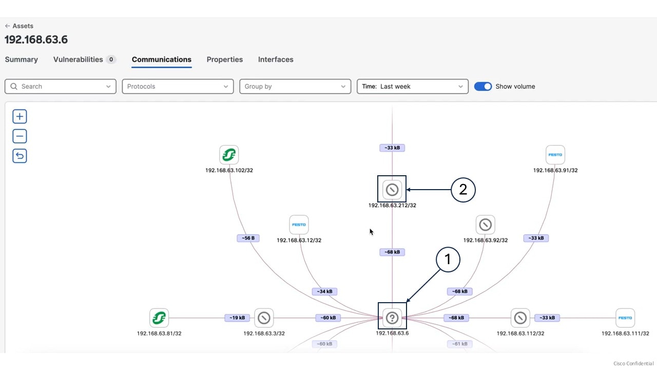
The communications map displays the various interactions of an asset. It helps you assess the internal communications of an asset.

You can filter the data to see specific communications. When you select a communication, a side panel opens showing observed protocols, exchange volumes, and source or destination asset information.

Procedure


Step 1

From the main menu, choose Assets.

Step 2

Select the asset name.

Step 3

Click Communications.

Step 4

To organize asset communications:

  • Use the Time field to sort by the required time period.

  • Use the Group by field to sort by Network or Functional Group.

    If you select

    Then

    Network,

    the filter groups all assets that communicate with the selected asset by their subnets.

    It shows only the subnet information, not the individual assets.

    Functional Group,

    the filter groups all assets that communicate with the selected asset by their functional groups.

    It shows only the functional groups, not the individual assets.


The Communication page displays asset vendor icons along with their IP or MAC addresses.

Callouts

Descriptions

(1)

It indicates that an asset does not have a vendor.

(2)

It indicates that the vendor is known, but its icon is unavailable.


Note


You can click group nodes to explore groups. This shows assets within each group and lets you investigate further.


Asset clustering

Manual asset grouping based on network definitions and communications is difficult. Asset clustering simplifies this process by organizing assets into functional groups according to their network communication patterns.

The system uses an algorithm to distinguishes between OT and IT assets and includes all OT assets in asset clustering. It then suggests a list of functional groups.

Asset movement

Asset clustering identifies assets that can move between functional groups, move to an ungrouped list, or move from the ungrouped list to a group. The algorithm recommends which assets to transfer and provides an updated list of functional groups.

If you add or remove a sensor or delete an asset, the algorithm suggests new functional groups based on the latest data. The asset clustering result does not change until the communication pattern changes.

Types of functional groups

Asset clustering suggests two types of functional groups: communication-based groups and named groups. A named group can have only one asset, while a communication-based group must have at least two assets. Asset clustering may suggest new functional groups that exclude the most significant assets.

Perform asset clustering

You can perform asset clustering on a specific asset, a functional group, or a sensor. Access this feature from the Functional Group page, Sensor Applications page, Assets page, or the individual asset detail page.

Procedure


Step 1

From the main menu, choose Configuration > Functional Groups.

Step 2

Click Start asset clustering.

The system then suggests functional groups in the list.

Step 3

To review, click the Functional Group name.

Step 4

To view communications between assets in a functional group, click Map.

The lightning symbol shows the most significant asset in the group.

Step 5

To change the Functional Group name, click Edit Name.

Step 6

Click Accept to create the functional group.


What to do next

Accept or discard the suggested functional groups before you rerun asset clustering. If you click Discard, the system ungroups the recommended assets and includes them in the next asset clustering run.

Asset Clustering for a Limited Set of Assets

This function allows you to perform focused asset clustering on a limited set of assets. Select assets to define the scope of your asset clustering. The results suggest functional groups that are impacted by the selected assets and exclude unrelated groups.

Procedure


Step 1

From the main menu, choose Assets.

Step 2

Check the checkboxes next to the asset names in the Name column.

Step 3

Click the More actions drop-down arrow.

Step 4

Click Run Asset Clustering from the drop-down list.

The Functional Group Asset Clustering pop-up appears.

Step 5

Click Start.

The asset clustering scope is the selected assets.


Asset Clustering for a Specific Functional Group

This function allows you to perform focused asset clustering for a specific functional group. The selected functional group defines the scope of the asset clustering. The system runs asset clustering on all assets, and once complete, only the impacted functional groups and asset information appear. The results suggest which assets should be part of the functional group and which should be removed.

Procedure


Step 1

From the main menu, choose Assets.

Step 2

Click the group name in the Functional Group column.

The View Functional Group panel appears.

Step 3

Click the More actions drop-down arrow.

Step 4

Click Run Asset Clustering from the drop-down list.

The Functional Group Asset Clustering pop-up appears.

Step 5

Click Start.


Asset Clustering for Selected Sensors

This function allows you to perform focused asset clustering for a specific sensor. The selected sensor serves as the scope for clustering. It runs asset clustering for assets detected by the selected sensor.

Procedure


Step 1

From the main menu, choose Configurations > Sensor Applications.

Step 2

Check the check-box of sensor application.

Step 3

Click Run Asset Clustering.

The Functional Group Asset Clustering pop-up appears.

Step 4

Click Start.


Asset Clustering for Individual Assets

This function allows you to perform focused asset clustering for a individual asset. The selected assets serve as the scope for clustering.

Procedure


Step 1

From the main menu, choose Assets.

Step 2

Click the asset name in the Name column.

Step 3

Click the drop-down arrow of the Functional group actions field.

Step 4

Click Run Asset Clustering from the drop-down list.

The Functional Group Asset Clustering pop-up appears.

Step 5

Click Start.


Lock Group

When you lock the group, it stays out of asset clustering. While it's locked, no assets get added or removed during asset clustering.

Procedure


Step 1

From the main menu, choose Assets.

Step 2

Click the group name in the Functional Group column.

The View Functional Group panel appears.

Step 3

Click the More actions drop-down arrow.

Step 4

Click Lock Group from the drop-down list.

The Lock Group pop-up appears.

Step 5

Click Lock.


Move Asset from One Group to Another

You can adjust your functional group by moving assets between groups, even if the algorithm cannot add a specific asset to your group.

Procedure


Step 1

From the main menu, choose Assets.

Step 2

Check the checkbox next to the assets.

Step 3

Click the More actions drop-down arrow.

Step 4

Click Add selected to group from the drop-down list.

The Add Selected To Group panel appears.

Step 5

Click the Functional Group drop-down arrow.

Step 6

Choose the group from the drop-down list.

Step 7

Click Add.

The Add Selected to Group warning appears.

Step 8

Click Add.

Note


After you move assets from one group to another, the system deletes any group that is left with a single asset automatically.

Note


You can also move an asset to another group from its individual detail page.


Delete the Functional Group

Procedure


Step 1

From the main menu, choose Assets.

Step 2

Click the group name from the Functional Group column.

The View Functional Group side panel appears.

Step 3

Click Delete group.

The Delete Group window appears.

Step 4

Click Delete.


Remove Asset from Functional Group

To remove asset from functional group:

Procedure


Step 1

From the main menu, choose Assets.

Step 2

Check the checkbox to select the asset name in the Name column.

Step 3

Click the More actions drop-down arrow.

Note


Accept or discard the suggested functional groups to access More actions field.

Step 4

Click Remove asset from the group from the drop-down list.

The Remove From Group pop-up appears with a note.

Step 5

Click Remove.


Alerts dashboard

An Alerts dashboard is a monitoring interface that allows you to:

  • filter alerts by severity (Critical, High, Medium, or Low),

  • access alert summaries and instance details, and

  • configure alert types from the summary page.

Active and cleared alerts

  • Active: The Active tab shows all active alerts from the Cyber Vision Center.

  • Cleared: When an alert is no longer valid, it appears in the Cleared tab.


Note


Cleared alerts stay available for up to 14 days.


Alert table

  • Alert Type column lists alert types such as Severe vulnerabilities in monitored entities and Prohibited Vendors.

  • Trigger column lists vulnerabilities.

  • Instances column lists impacted asset count.

  • Severity column lists severity levels.

  • Triggered By column lists categories.

Alerts configuration

You configure alerts by managing alert rules and types.

Alert types

Cyber Vision Center, by default, includes two alert types:

  • Severe Vulnerabilities in Monitored Entities: Monitors assets within selected entities and raises alerts for high-scoring vulnerabilities.

  • Prohibited Vendors: Raises alerts for assets associated with prohibited vendors.


Note


You can enable Syslog notifications to send alerts generated for a specific alert type to the Syslog server.


Alert rules

Each alert type includes a default alert rule:

Add new alert rules

You add new alert rules to monitor asset vulnerabilities. When a vulnerability matches the rule, the alert appears on the Alerts dashboard.

Adding rules under the Severe vulnerabilities in monitored entities type changes the number of alerts on the dashboard. The Prohibited Vendors alert type does not include a Create New Rule option.


Note


You cannot add new alert rules to the Prohibited Vendors alert type.


Note


Upgrading the Cyber Vision Center purges old alert rules. The system displays only default alert rules.


Procedure

Step 1

From the main menu, choose Configuration > Alerts.

Step 2

Select the Severe vulnerabilities in monitored entities alert type.

Step 3

Click Create new rule.

Step 4

Add Alert Rule Name and select the Severity and Entity type.

Step 5

Select either organization hierarchy level or functional groups in the Entity selection page.

Note


Entity selection depends on the Entity type selected in the Rule name and entity type page.

  • Select the organization hierarchy level. Check the Assets seen by Unknown data sources checkbox.

  • Select one or more functional groups. Check the Include Ungrouped assets checkbox.

Step 6

Select one of these scoring systems in the Scoring system and threshold tab.

  • Cisco Security Risk Score: enter a Cisco Security Risk Score threshold number between 34 and 100.

  • CVSS: enter a CVSS score threshold number between 7 and 10.

Note


Cisco Security Risk Score is the default scoring system, but you can switch to CVSS.

Step 7

Review the Summary and then click Save.


Manage alert rules

You can manage alert rules for Severe vulnerabilities in monitored entities by editing, duplicating, or deleting them. For the Prohibited Vendors alert type, you can only edit the alert rules.

Procedure

Step 1

From the main menu, choose Configuration > Alerts.

Step 2

Select the alert type.

Step 3

Locate the alert rule and click the ellipsis (…) in the Actions column.

Step 4

To manage alert rules:

  • For the Severe vulnerabilities in monitored entities alert type, choose Edit, Duplicate, or Delete.

  • For the Prohibited Vendors alert type, select Edit.

Step 5

Change settings as needed and click Save.

  • For Severe Vulnerabilities in Monitored Entities, you can update the Alert Rule Name, Severity, Entity selection, and Scoring system and threshold.

  • For Prohibited Vendors, you can update the Alert Rule Name, Severity, and Vendors.


The alert rule updates the alert count displayed on the Alerts page accordingly.

Pause and resume alert types

Pause an alert type to temporarily stop creating new alerts for all rules under it. Existing alerts stay the same. Resume a paused alert type to restart creating new alerts for all rules.

You can manage the alerts by pausing and resuming the alert types.

Procedure

Step 1

From the main menu, choose Configuration > Alerts.

Identify the alert types you wish to pause or resume.

Step 2

Click Pause or Resume in the Actions column.

Step 3

Click Yes in the Warning pop-up window.


Enable or disable the syslog notifications for alert types

The system sends syslog notifications to the configured syslog server by default whenever an alert is raised, cleared, or its status changes.

  • The syslog message includes these details, which are common to all alert rules:

    • CEF:0

    • vendor: Cisco

    • product: Cyber Vision

    • version: 2.0

    • event_class_id: alert_raised OR alert_cleared OR alert_muted

    • event_name: alert type name

    • severity id: 2 (The value changes based on the severity of the alert rule.)

    • cat=alert category

    • SCVAuthorId=user uuid (optional): populated only if user acknowledged an alert manually, empty when system cleared the alert

    • alertRuleId=alert rule uuid

    • alertId=alert uuid

    • msg=The value changes based on the alert type and the event_class_id.

    • assetId

    • assetName

    • assetFunctionalGroupId (empty when ungrouped)

    • center-id=uuid of center

    • sensorNames

  • The syslog message includes these details for Severe vulnerabilities in monitored entities:

    • vulnNumber: for example, CVE-2023-10025

    • vulnName

    • vulnCVSSscore

    • vulnCSRSscore

  • The syslog message includes "vendorName" for Prohibited Vendors.

Procedure


Step 1

From the menu, choose Configure > Alerts.

Step 2

Select an alert type.

Step 3

Enable or disable the Syslog Notification button.


Configuration

Organization hierarchies

The Organization Hierarchy represents a structured arrangement of levels that logically group entities.

Hierarchy structure

  • Each node in the hierarchy is called a level.

  • The root level of the hierarchy is referred to as Global, and it is a system-defined level.

Nesting limit

The Cyber Vision Center supports nesting of up to five sub-levels. Once this limit is reached, you cannot add more levels due to the system-defined restriction.

Add, edit, and delete levels in the organization hierarchy

Procedure

Step 1

From the main menu, choose Configuration > Organization Hierarchy.

Step 2

Locate the level and click the ellipsis (…) under the Action column.

Step 3

From the drop-down list:

  • Select Add Level, enter the level name, and click Add to create the new level.

  • Select Edit, modify the level name, and save the changes to edit the level.

  • Select Delete and confirm to remove the level.

    Note


    The Delete option does not appear for a level if:

    • It is a global level.

    • It has child levels.

    • It has a non-zero count, meaning entities such as sensors or PCAPs are assigned to it.


Network definitions

Cyber Vision identifies the networks you want to monitor to provide an accurate asset inventory and security posture assessment. You specify the IP addresses and VLANs of your networks by defining your organization's internal IT and OT networks. This approach makes the data more relevant.

Cyber Vision Center offers default network configurations based on RFC1918 addresses and ship the product with default private networks (10.0.0.0/8, 172.16.0.0/12, 192.168.0.0/16).

Asset detection and network types

The Cyber Vision Service treats all assets detected through PCAP analysis or sensors as part of the same "network." This may result in inaccuracies when aggregating components into physical assets or may lead to irrelevant asset data. Cyber Vision resolves this by allowing you to define your network into three network types:

  • OT Internal: includes assets like PLCs or HMIs.

  • IT Internal: includes assets like laptops and other IT-related items, and

  • External: excludes and removes assets found in this network type from the asset inventory.

Network administrator role

The network administrator determines the type of networks needed. The administrator chooses the network type and checks for duplicate IP ranges.

Network definition in classic and new UI

The network administrator determines the type of networks you need. They choose the network type and check for duplicate IP ranges.

  • Classic UI: You can create network definitions. See Define a subnetwork for more information.

  • New UI: You can view existing network definitions and assign them to specific organization hierarchy level, but cannot create or modify them. See Assign network to organization hierarchy for more information.

Default network definitions

Cyber Vision automatically defines:

  • OT Internal networks: based on RFC1918 (IPv4) or RFC 4193 (IPv6) subnets, and

  • External networks: defined as everything else.

Assign network to organization hierarchy

To assign a network to an organization hierarchy, follow these steps:

Procedure

Step 1

From the main menu, choose Configuration > Network Definition.

Step 2

Locate the network you want to assign and click Assign.

Step 3

Select the organization hierarchy level.

Step 4

Click Assign to complete the process.


PCAP

Cyber Vision allows you to upload Packet Capture (PCAP) data that captures network traffic from your OT network. You can import PCAP files to Cisco Cyber Vision.

A PCAP file captures communication packets between various assets. When imported into Cisco Cyber Vision, the assets are identified and created with their respective properties and communication patterns. Once created, assets appear not only on the dashboard but across the system on all pages.

To upload PCAP, use the classic UI. See PCAP Upload.


Important


PCAP files are imported using the Classic UI. In the Beta UI, you can only view the PCAP files that have already been uploaded.


Uploaded PCAPs appear in Configuration > PCAPs.

To assign multiple PCAP files to the Organization Hierarchy, follow these steps:

Procedure


Step 1

From the main menu, choose Configuration > PCAPs.

Step 2

Click Assign at the end of the row for the PCAP file you need to assign.

  1. To assign multiple PCAP files to the Organization Hierarchy, follow these steps:

    1. Check the checkboxes of the desired PCAP files.

    2. Click Assign Selected to Organization Hierarchy.

Step 3

Choose the Organization Hierarchy.

Step 4

Click Assign.

Note


Each PCAP is responsible for Asset creation in Cisco Cyber Vision.


Sensor Applications

Cyber Vision Sensors capture network traffic and perform Deep Packet Inspection of industrial protocols to extract information. They send metadata to the center for storage and analytics. The sensor software is embedded into Cisco networking equipment as an IOx application. Sensors integrate into existing Cisco network devices such as routers and switches or can be deployed as standalone devices.

The Sensor Applications interface shows the Network Device Name, Health Status, Processing Status, and Organization Hierarchy.

Health status:

  • New

    This is the sensor's first status when it is detected by the Center. The sensor is asking the DHCP server for an IP address.

  • Request Pending

    The sensor has asked the Center for a certificate and is waiting for the authorization to be enrolled.

  • Authorized

    The sensor has just been authorized by the Admin or the Product user. The sensor remains as "Authorized" for only a few seconds before displaying as "Enrolled".

  • Enrolled

    The sensor has successfully connected with the Center. It has a certificate and a private key.

  • Disconnected

    The sensor is enrolled but isn't connected to the Center. The sensor may be shut down, encountering a problem, or there is a problem on the network.

Processing status:

  • Disconnected

    The sensor is enrolled but isn't connected to the Center. The sensor may be shut down, encountering a problem, or there is a problem on the network.

  • Not enrolled

    The sensor is not enrolled. The health status is New or Request Pending. The user must enroll the sensor for it to operate.

  • Normally processing

    The sensor is connected to the Center. Data are being sent and processed by the Center.

  • Waiting for data

    The sensor is connected to the Center. The Center has treated all data sent by the sensor and is waiting for more data.

  • Pending data

    The sensor is connected to the Center. The sensor is trying to send data to the Center but the Center is busy with other data treatment.

Installed sensors appear under Configuration > Sensor Applications.

Assign the Sensor to the Organization Hierarchy

To assign the sensor to the Organization Hierarchy, follow these steps:

Procedure

Step 1

From the main menu, choose Configuration > Sensor Applications.

Step 2

Click Assign at the end of the network device row that needs assignment.

  1. To assign the multiple sensors to Organization Hierarchy, follow these steps:

    1. Check the checkboxes of the desired sensors.

    2. Click Assign Selected to Organization Hierarchy.

Step 3

Choose the Organization Hierarchy.

Step 4

Click Assign.

Note


Each sensor is responsible for asset creation in Cisco Cyber Vision.


Use Cases

Review All PLC and SCADA Data Servers in the Paint Shop

Procedure


Step 1

Organize Network in the Old UI.

  1. Define a network within the Network Organization section.

  2. Ensure that the network includes the subnet for both the PLC and SCADA network.

    For example, use the subnet 192.168.41.0/24.

Step 2

From the main menu, choose Assets.

Step 3

Click the filter icon at the top-right corner of the table.

Step 4

To filter the asset list, search for the network name in the Network column.

Review the different assets in the paint shop.

Note


Users cannot edit the network definition information in the new UI.

Step 5

To see the details of the assets, click the asset name.


Analyze and Acknowledge All Vulnerabilities with a CVSS Score Above Nine

Users can review vulnerabilities through either the vulnerability list for each asset or the comprehensive list of vulnerabilities. Both lists include a filter to display specific CVSS scores.

Procedure


Step 1

From the main menu, choose Assets.

Step 2

Click the asset Name.

Step 3

Click Vulnerabilities.

Step 4

Click the filter icon at the top right corner of the table.

Step 5

Click the drop-down arrow of the CVSS Score column.

Step 6

Select Critical from the drop-down list.

This will show vulnerabilities with a CVSS score between 9.0 and 10.

Step 7

To acknowledge the vulnerability, click Acknowledge.

Acknowledging the vulnerability will hide it from dashboard counters, clear alerts, and make filtering easier.