Mount the Chassis


Note

Do not remove the rubber feet included with the ASA because they are needed for proper cooling for all mounting orientations.


Desktop-Mount the Chassis

You can mount the chassis on a desktop by placing it on a desk in a horizontal position. Make sure there are no blockages or obstructions within one inch of the top of the chassis or within .5 inch of the sides and back, so that nothing interferes with cooling. Do not remove the rubber feet included with the chassis. They are also needed for proper cooling.
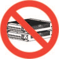
Figure 1. Do Not Stack the Chassis

Caution

Do not stack the chassis on top of another chassis. If you stack the units, they overheat, which causes the units to power cycle.


Wall-Mount the Chassis

Follow these steps to mount the chassis on a wall. You can purchase a wall-mount kit. The part number for the wall-mount kit is ASA5506-WALL-MNT= .

Procedure


Step 1

Choose a location on the wall for the chassis.

Step 2

Use the two Cisco-provided screws and anchors from the optional wall-mount kit.

If you are mounting the chassis onto something other than drywall, such as wood or sheet metal, anchors may not be required.

Step 3

Use a pencil, ruler, and level to mark locations for the two mounting screws.

The width and length of the chassis are 7.87 x 9.23 inches ( 20 x 23.44 cm). The mounting holes in the chassis are in the middle length-wise (that is, 6.372 inches from front and back), while the holes are inset from the opposite edges 0.75 inches (1.9 cm).

Thus, you need to make two level marks 6.37, or approximately 6-3/8, inches (16.18 cm) apart.

Figure 2. Mark the Locations of the Two Mounting Screws
Step 4

Drill a hole into the wall at each mark.

These holes should be slightly smaller in diameter than your anchors. The recommended drill hole size is 3/16".

Step 5

Insert the anchors into the holes and be sure they are properly seated.

Step 6

Fasten each screw into its anchor until it protrudes about 1/4 inch.

Step 7

Pick up the chassis, align the screws in the anchors with the holes in the bottom of the chassis, move the chassis toward the wall until the screw heads are in the chassis, and then slide the chassis down until it rests on the screws.

You can only mount the chassis with the front panel oriented toward either the ceiling or the floor. Wall mounting in other orientation is not supported.


What to do next

Install the cables as described in Quick Start Guide for your default software configuration.

Rack-Mount the Chassis

The rack-shelf kit (part number 800-107605-01) contains the following items:


Note

There are two sets of four screws that you can use to secure the chassis to your rack. Chose the screws that fit your rack.
  • Rack shelf (part number 700-122662-01)

  • Two sliding rack trays (part number 800-107648-01)

  • Two cable guides (part number 700-122664-01)

  • Twelve Phillips M3 x 7-mm screws (part number 48-1921-01); use these screws to install the cable guides.

  • Four Phillips 12-24 x 0.75-inch screws (part number 48-0440-01); depending on your rack type, use these screws to secure the sliding-rack tray to your rack.

  • Four Phillips 10-32 x 0.75-inch screws (part number 48-0441-01); depending on your rack type, use these screws to secure the sliding-rack tray to your rack.


Note

You need six Phillips 6-32 x 0.25-inch screws (part number 48-0421-01) to secure the sliding rack tray onto the chassis. These screws may be in the kit, but if not, you must provide them. Also there will be six extra Phillips M3 x 7-mm screws. Do not use these to secure the sliding rack onto the chassis, because these screws are bigger and will not be as tight.


Note

You mount only one ASA 5506H-X in the rack-mount shelf.

The dimensions of the ASA 5506H-X are 3.46 x 18.3 x 19.5 inches (8.79 x 46.48 x 49.52 cm). The PID is asa5506h-rack-mnt=.


Procedure


Step 1

Install the cable guides on the rack shelf:

Figure 3. Attach the Cable Guides to the Rack Shelf Flange

1

Two cable guides (part number 700-122664-01)

Left cable guide rack shelf cutouts

3

Right cable guide rack shelf cutouts

4

Six of the twelve Phillips M3 x 7-mm screws (part number 48-1921-01)

  1. Align the cable guides with the cutouts on the rack shelf flange (see figure above).

  2. At the rear of the rack shelf, attach the left and right cable guides using six of the twelve Phillips M3 x 7-mm screws (part number 48-1921-01).

    Note 

    Drive the screws in while facing the back of the rack shelf.

  3. Set the rack shelf aside. Continue with Step 2 to install the sliding rack tray on the chassis.

    The figure in Step 8 shows the rack shelf with the cable guides attached.

Step 2

Place the chassis with the top facing down on a large, stable work area.

Step 3

Invert the sliding rack tray and position it on the chassis. You can mount the chassis with the front or rear panel facing front.

Figure 4. Install the Sliding Rack Tray on the Chassis

1

Three of the six 6-32 x 0.25-inch screws (part number 48-0421-01) (you may have to provide these)

Step 4

Adjust the position of the chassis and the sliding rack tray until the three mounting holes in the dimples in the bottom of the sliding rack tray are aligned with the mounting holes in the bottom of the chassis.

Step 5

Tighten the screws to lock the chassis into place on the sliding rack tray.

Step 6

Carefully turn the sliding rack tray right-side up.

Step 7

Install the power supply on the sliding rack tray behind the chassis.

Figure 5. Install the Power Supply in the Sliding Rack Tray

1

Velcro straps for power supply

2

Velcro straps for power supply

3

Power supply stop

4

Power supply stop

5

Rear sliding stop and screw (one of two screws on the sliding stop)

  1. Loosen the Velcro straps and place the power supply on the sliding rack tray behind the chassis.

    Make sure the AC inlet cord faces the rear.
  2. Align the power supply to the side and rear stops.

    If the rear sliding stop is not touching the power supply, loosen the two screws, slide the stop up to touch the power supply, and then retighten screws.

  3. Re-engage the Velcro straps and tighten them to secure the power supply.

    Figure 6. Tighten the Velcro Straps

    1

    Velcro straps tightened over power supply

Step 8

Slide the sliding-rack tray into the rack shelf.

Figure 7. Slide the Sliding-Rack into the Tray Rack Shelf
Step 9

The chassis is now installed in the sliding-rack tray, which is installed in the rack shelf. Repeat Steps 1 through 8 to install a second chassis. Use the second sliding rack tray and three more 6-32 x 0.25-inch screws to install a second chassis to sliding rack tray and then onto the rack shelf (see Step 3).

Figure 8. Completed Sliding Rack Tray in Rack Shelf Installation
Step 10

Install the rack shelf into your rack using the correct screws (12-24 x 0.75 inch or 10-32 x 0.75 inch) from the rack-mount kit that fit your rack type.

You can now attach your power supply cord and run it through the cable guides.


What to do next

Install the cables according to your default software configuration as described in the Cisco ASA 5506-X Series Quick Start Guide.

Install the ASA 5506H-X in a DIN Rail

You can use the 7.5-mm thick 45-mm wide top hat DIN rail for the ASA 5506H-X. Secure the DIN rail to the mounting surface approximately every 7.8 inches (200 mm) and use end-anchors appropriately.


Note

We recommend that you install the ASA 5506H-X on a steel DIN rail for extra stability.


To attach the ASA 5506H-X to a 35-mm wide DIN rail, follow these steps:

Procedure


Step 1

Attach the DIN rail bracket to the back of the chassis using the four screws provided.

Figure 9. Attach the DIN Rail Bracket to the ASA 5506H-X
Step 2

Locate the plastic tab on the end of the DIN rail bracket that extends past the chassis. Press the tab in and slide the plastic latch piece out while the tab is pressed down to put it into the locked position.

Step 3

Turn the chassis sideways so that the power connector is near the top.

Step 4

Position the rear edge of the chassis directly in front of the DIN rail making sure that the DIN rail fits in the space between the plastic latch and the metal hook.

Step 5

Position the chassis so that the hook on the DIN rail bracket hooks onto the top edge of the DIN rail. The weight of the chassis can rest on the hook temporarily while the DIN rail bracket latches are secured.

Step 6

Push the DIN rail bracket latch up when the chassis is over the DIN rail to secure it. This snaps the latch into the closed position which locks it onto the DIN rail.

Figure 10. ASA 5506H-X Installed with the DIN Rail
The chassis is now installed in the DIN rail.

What to do next

Install the cables as described in the Cisco ASA 5506-X Series Quick Start Guide.