Overview

About the ASA 5506-X, ASA 5506W-X, and ASA 5506H-X

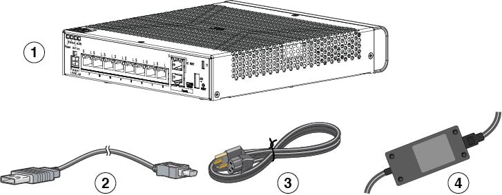
The Cisco ASA 5506-X, ASA 5506W-X, and ASA 5506H-X adaptive security appliances are part of the ASA 5500-X of next-generation mid-range ASAs and are built on the same security platform as the rest of the ASA family.


Note

Your ASA 5506-X ships with either ASA or Firepower Threat Defense software preinstalled. To reimage your device, see Reimage the Cisco ASA or Firepower Threat Defense Device.


This next-generation ASA delivers unprecedented levels of defense against threats to the network with deeper web inspection and flow-specific analysis, improved secure connectivity via end-point security posture validation, and voice and video over VPN support. It also provides enhanced support for intelligent information networks through improved network integration, resiliency, and scalability.

This ASA is a smaller form-factor chassis, intended primarily for desktop or wall-mounting, although one or two can be mounted in a single rack shelf. The ASA has a standard 1 RU chassis. See Cisco ASA 5500-X Series Next-Generation Firewalls to compare the performance metrics and capabilities of the 5500-X ASAs.

Figure 1. Do Not Stack the ASA Chassis

Note

Do not stack the ASA chassis on top of another ASA chassis. If you stack the units, they will overheat, which causes the units to power cycle.

The ASA 5506-X, 5506W-X, and ASA 5506H-X have been validated for the following security standards certifications:

  • Federal Information Processing Standards (FIPS) 140-2 for ASA 9.12.x

  • Common Criteria (CC) certification for the Network Device Collaborative Protection Profile, (NDcPPv2.1), VPN Gateway Module (VPNGW_MOD_v1.0), and Firewall Module (FW_MOD_v1.3) for ASA 9.12.x

  • Common Criteria (CC) certification for the Network Device Collaborative Protection Profile, (NDcPPv2.2E), the IPS Extended Profile (IPSEP 2.11), Firewall Collaborative Protection Profile Module (MOD_FW_v1.4e), and Virtual Private Network Gateway Protection Profile Module (MOD_VPNGW_v1.1) for FTD 6.4.x

ASA 5506W-X Wireless Features

The ASA 5506W-X supports two high-performing spatial stream rates over a deployable distance with high reliability when serving clients. The ASA 5506W-X contains two simultaneous dual-band radios (2.4-GHz and 5-GHz 802.11n MIMO radios) in a controller-based mode or autonomous mode. It has integrated internal antennas that support full interoperability with leading 802.11n clients. The radio hardware supports Unified, FlexConnect, and Monitor-mode.

The ASA 5506W-X has the following processor features:

  • 128 MB NAND flash size

  • 1 MB NOR flash size

  • 128 MB DDR2 memory bus, x32

The 2.4 GHz and 5 GHz 802.11n radios have the following features:

  • 802.11n standard compliant

  • A-MPDU TX

  • HT Duplicate Mode

  • 2TX x 2RX

  • 2-spatial streams, 300 Mbps PHY rate

  • Maximal ratio combining (MRC)

  • Cyclic Shift Diversity (CSD)

  • MCS0-MCS15; Short or Long Guard Intervals

  • DFS for UNII-2 and UNII-2 Extended channels, including 0.5us radar pulse detection

The ASA 5506W-X is configured with four single-band, inverted-F antennas (two 2.4-GHz and two 5-GHz), which are evenly spaced inside the top of the chassis. Peak gains are approximately 3 dBi in the 2.4-GHz band and 5 dBi in the 5-GHz band.

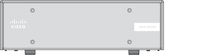
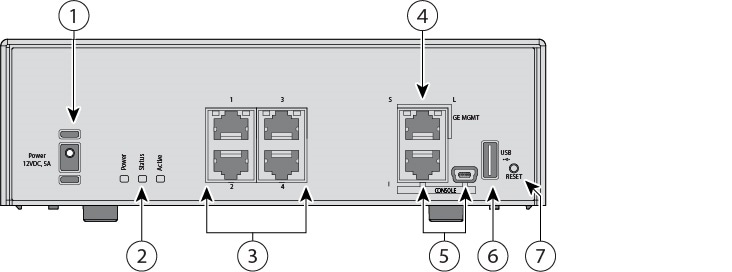
ASA 5506H-X Features

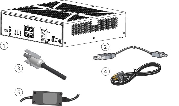
The ASA 5506H-X is a hardened version of the 5506-X with a ruggedized chassis, power supply, SSD, and four ports instead of eight. It is ruggedized because it supports a much wider industrial operational temperature range (-20C to 60C), meets the harsh EMI and environmental criteria for the IEC1613 and IEC 61850-3 power substation standards, and meets IEC60529 IP40 for ingress protection.

The ASA 5506H-X ships with a ruggedized 5V-5.3V barrel power supply that provides 22 W. Or you can order an optional DC power supply that supplies 24V DC (part number PWR2-20W-24VDC) or 20W 20-60V DC (part number PWR2-22W-20-60VDC).


Note

Before beginning any of the procedures described in this book, be sure to read the Regulatory and Compliance Safety Information for the Cisco ASA 5506-X series and follow proper safety procedures.


Package Contents

The following figure shows the package contents for the ASA 5506-X and ASA 5506W-X. Note that the contents are subject to change and your exact contents might contain additional or fewer items.

Figure 2. ASA 5506-X and 5506W-X Package Contents

1

Chassis

2

USB console cable (Type A to Type B)

3

Power cord

4

Brick power supply

The following figure shows the package contents for the ASA 5506H-X. Note that the contents are subject to change and your exact contents might contain additional or fewer items.

Figure 3. ASA 5506H-X Package Contents

1

Chassis

2

USB console cable (Type A to Type B)

3

Power cord retention lock

4

Power cord

5

Power supply

Front Panel

The following figure shows the front panel of the ASA 5506-X. The ASA 5506W-X has an identical front panel. Note that there are no connectors or LEDs on the front panel.

Figure 4. 5506-X and 5506W-X Front Panel
The following figure shows the front panel of the ASA 5506H-X. Note that there are no connectors or LEDs on the front panel.
Figure 5. 5506H-X Front Panel

Rear Panel

The following figure shows the rear panel of the ASA 5506-X. The 5506W-X has an identical rear panel.

Figure 6. ASA 5506-X and 5506W-X Rear Panel

1

Status LEDs

The locations and meanings of the status LEDs are described in LEDs.

2

Power cord socket

The chassis power-supply socket. See Power Supply Modules for more information about the chassis power supply.

Note 

The ASA is powered on when you plug in the AC power supply.

3

Network data ports

Eight Gigabit Ethernet RJ-45 (8P8C) network I/O interfaces. The ports are numbered (from left to right) 1, 2, 3, 4, 5, 6, 7, 8. Each port includes a pair of LEDs, one each for connection status and link status. The ports are named and numbered Gigabit Ethernet 1/1 through Gigabit Ethernet 1/8. See Network Ports for additional information.

4

Management port

A Gigabit Ethernet interface restricted to network management access only. Connect with an RJ-45 cable.

5

Console ports

Two serial ports, a mini USB Type B, and a standard RJ-45 (8P8C), are provided for management access via an external system. See Console Ports for additional information.

6

USB port

A standard USB Type A port is provided that allows the attachment of an external device, such as mass storage. See Internal and External Flash Storage for additional information.

7

Reset button

A small recessed button that if pressed for longer than three seconds resets the ASA to its default “as-shipped” state following the next reboot. Configuration variables are reset to factory default. However, the flash is not erased and no files are removed.

Note 

You can use the service sw-reset-button command to disable the reset button. The default is enabled.

Note 

Pressing the reset button on the ASA 5506W-X does not affect the AP configuration, but it causes any unsaved AP configuration to be lost, because the system has rebooted. After the system reboots, if you want a default AP configuration, use the hw-module module wlan recover configuration command to recover the AP configuration.

8

Lock slot

The slot accepts a standard Kensington T-bar locking mechanism for securing the ASA.

The following figure shows the rear panel of the 5506H-X.

Figure 7. ASA 5506H-X Rear Panel

1

Power cord socket

The chassis power-supply socket; see Power Supply Modules for more information about the chassis power supply.

Note 

The ASA is powered on when you plug in the AC power supply.

2

Status LEDs

The locations and meanings of the status LEDs are described in LEDs.

3

Network data ports

Four Gigabit Ethernet RJ-45 (8P8C) network I/O interfaces. The ports are numbered (from top to bottom) 1, 2, 3, 4,. Each port includes a pair of LEDs, one each for connection status and link status. The ports are named and numbered Gigabit Ethernet 1/1 through Gigabit Ethernet 1/4. See Network Ports for additional information.

4

Management port

A Gigabit Ethernet interface restricted to network management access only. Connect with an RJ-45 cable.

5

Console ports

Two serial ports, a standard RJ-45 (8P8C), and a mini USB Type B, are provided for management access via an external system. See Console Ports for additional information.

6

USB port

A standard USB Type A port is provided that allows the attachment of an external device, such as mass storage. See Internal and External Flash Storage for additional information.

7

Reset button

A small recessed button that if pressed for longer than three seconds resets the ASA to its default “as-shipped” state following the next reboot. Configuration variables are reset to factory default. However, the flash is not erased and no files are removed.

Note 

You can use the service sw-reset-button command to disable the reset button. The default is enabled.

LEDs

Facing the rear of the ASA 5506-X and ASA 5506W-X chassis, the LEDs are located on the top left edge (facing the front of the chassis, they are in the back right corner of the top). Facing the rear of the ASA 5506H-X, the LEDs are located on the bottom left of the chassis. The network port LEDs are at the top sides of each network port. See Rear Panel for more information.

The following figure shows the LEDs on the top left edge.

Figure 8. LEDs

1

Power

Power supply status:

  • Unlit—Power supply off.

  • Green—Power supply on.

See Power Supply Modules for additional power information specific to your specific ASA.

2

Status

System operating status:

  • Green—Normal system function.

  • Amber—Critical alarm indicating one or more of the following:

    • Major failure of a hardware or software component.

    • Over-temperature condition.

    • Power voltage outside the tolerance range.

3

Active

Status of the failover pair:

  • Green—Failover pair operating normally. The LED is green always unless the ASA in an HA pair.

  • Amber—When the ASA is in an HA pair, the LED is amber for the Standby unit.

  • Unlit—Failover is not operational.

4

wLAN

Not in use on the ASA 5506-X or the ASA 5506-H.

Association status of the wireless connection on the ASA 5506W-X:

  • Green, flashing—Normal operating condition, but no wireless client is present.

  • Green—Normal operating condition, at least one wireless client is associated.

  • Amber, flashing—Software upgrade in progress.

  • Green, red, amber sequence—Discovery/join process in progress.

  • Red, flashing —Ethernet link not operational.

  • Unlit—Wireless is not operational.

Network Port Status

On the rear panel of the ASA 5506-X and ASA 5506W-X, a pair of LEDs (link status and connection status) for each of the eight Gigabit Ethernet network ports, and the Gigabit Ethernet management port.

On the rear panel of the ASA 5506H-X, a pair of LEDs (link status and connection status) for each of the four Gigabit Ethernet network ports, and the Gigabit Ethernet Management port.

Link status (L):

  • Unlit—No link, or port is not in use.

  • Green—Link established.

  • Green, flashing—Link activity.

Connection-speed status (S):

  • One flash every three seconds—10 Mbps.

  • Two rapid flashes—100 Mbps.

  • Three rapid flashes—1000 Mbps.

Network Ports

There are eight 10/100/1000 baseT Ethernet network ports on the ASA 5506-X and ASA 5506W-X. Each RJ-45 (8P8C) copper port supports auto MDI/X as well as auto-negotiation for interface speed, duplex, and other negotiated parameters, and are MDI/MDIX compliant.

In addition, the ASA 5506W-X has a Gigabit Ethernet 1/9 port that is internal and connects to the WLAN module.

The ASA 5506H-X has four 10/100/1000 baseT Ethernet network ports. Each RJ-45 (8P8C) copper port supports auto MDI/X as well as auto-negotiation for interface speed, duplex, and other negotiated parameters, and are MDI/MDIX compliant.

Looking at the rear of the ASA 5506-X and ASA 5506W-X, where the ports are located, port 1 is on the left, and port 8 is on the right, next to the console and management ports. Each port is accompanied by a pair of LEDs, one each for link status (L) and connection status (S). The ports are named and numbered Gigabit Ethernet 1/1 through Gigabit Ethernet 1/8. The ports are named and numbered Gigabit Ethernet 1/1 through Gigabit Ethernet 1/4.

The four ports on the ASA 5506H-X are numbered differently. Looking at the rear of the ASA 5506H-X where the ports are located, ports 1 and 3 are at the top from left to right. Ports 2 and 4 are on the bottom from left to right. The ports are between the Status LEDs and the console and management ports. The ports are named and numbered Gigabit Ethernet 1/1 through Gigabit Ethernet 1/4.

Console Ports

The ASA has two external console ports, a standard RJ-45 port and a Mini USB Type B serial port. Only one console port can be active at a time. When a cable is plugged into the USB console port, the RJ-45 port becomes inactive. Conversely, when the USB cable is removed from the USB port, the RJ-45 port becomes active. The console ports do not have any hardware flow control. You can use the command-line interface (CLI) to configure your ASA through either serial console port by using a terminal server or a terminal emulation program on a computer.

In addition, the AP module inside the ASA 5506W-X has a console port, which is accessible by sessioning to the module's console via the session wlan console command in the ASA CLI.

RJ-45 Port

The RJ-45 (8P8C) port supports RS-232 signaling to an internal UART controller. The RJ-45 console port does not support a remote dial-in modem. You can use a standard management cable (Cisco part number 72-3383-01) to convert the RJ45-to-DB9 connection if necessary.

Mini USB Type B Port

The Mini USB Type B port lets you connect to a USB port on an external computer. For Linux and Macintosh systems, no special driver is required. For Windows systems, you must download and install a USB driver (available on software.cisco.com). You can plug and unplug the USB cable from the console port without affecting Windows HyperTerminal operations. We recommend shielded USB cables with properly terminated shields. Baud rates for the USB console port are 1200, 2400, 4800, 9600, 19200, 38400, 57600, and 115200 bps.


Note

For Windows operating systems, you must install a Cisco Windows USB Console Driver on any PC connected to the console port before using the USB console port. See Connect to the Console Port with Microsoft Windows for information on installing the driver.


Internal and External Flash Storage

The ASA contains one internal USB flash drive, and a standard USB Type A port that you can use to attach an external device. The USB port can provide output power of 5 volts, up to a maximum of 500 mA (5 USB power units).

Internal USB Device

An embedded eUSB device is used as the internal flash; it is identified as disk0.

External USB Drive (Optional)

You can use the external Type A USB port to attach a data-storage device. The external USB drive identifier is disk1. When the ASA is powered on, a connected USB drive is mounted as disk1 and is available for you to use. Additionally, the file-system commands that are available to disk0 are also available to disk1, including copy, format, delete, mkdir, pwd, cd, and so on.

If you insert a USB drive with more than one partition, only the first partition is mounted.

FAT-32 File System

The ASA only supports FAT-32-formatted file systems for the internal eUSB and external USB drives. If you insert an external USB drive that is not in FAT-32 format, the system mounting process fails, and you receive an error message. You can enter the command format disk1: to format the partition to FAT-32 and mount the partition to disk1 again; however, data might be lost.

Solid State Drive

The ASA 5506-X and ASA 5506W-X ship with an SSD installed that provides storage support. The SSD has 50 GB of useable space and is not field-replaceable. You must return the entire ASA to Cisco for drive replacement. The SSD is used by the software; there is no user access to the SSD.

The ASA 5506H-X ships with a ruggedized SSD installed that provides storage support. The SSD is an industrial-rated part so that it operates over the extended temperature range that the ASA 5506H-X supports. The SSD has 50 GB of useable space and is not field-replaceable. You must return the entire ASA to Cisco for drive replacement. The SSD is used by the software; there is no user access to the SSD.

Power Supply Modules

The ASA 5506-X and ASA 5506W-X ship with a 12-V brick power supply that provides 60 W.

The ASA 5506H-X ships with a ruggedized 5-V to 5.3-V barrel power supply that provides 22 W. The power supply supports an extended temperature range of -25 to 60°C. Or you can order an optional DC power supply that supplies 24 V DC (part number PWR2-20W-24VDC) or 20 W 20-60 V DC (part number PWR2-22W-20-60VDC).

Hardware Specifications

The following table contains hardware specifications for the ASA.

Mounting

  • Desk mountable; see Desktop-Mount the Chassis for more information.

    Caution 

    Do not stack the ASA chassis on top of another ASA chassis. If you stack the units, they overheat, which causes the units to power cycle.

  • Rack mountable in a rack tray. You can place two chassis side by side. See Rack-Mount the Chassis for more information.

    Note 

    One ASA 5506H-X fits in the rack tray. See Rack-Mount the Chassis for more information.

  • Wall mountable (ASA 5506-X and ASA 5506W-X only); see Wall-Mount the Chassis for more information.

  • DIN rail mountable (ASA 5506H-X only); the DIN rail is available for order from Cisco Systems. See Install the ASA 5506H-X in a DIN Rail.

Dimensions

7.87 x 9.23 x 1.94 inches (19.99 x 23.44 x 4.93 cm) including the feet (ASA 5506-X and ASA 5506W-X).

9.1 x 9.1 x 2.8 inches (23.11 x 23.11 x 7.11 cm) including the feet (ASA 5506H-X).

Weight

4 lb (ASA 5506-X and ASA 5506W-X)

6.7 lb (ASA 5506H-X)

DRAM

Total: 4 GB

Allotted to FW/VPN: 1.8 GB

Allotted to Module: 2.2 GB

Note 

The total memory is divided between the OS/Lina/SFR. These percentages may vary depending on your ASA software version.

Internal flash

8 GB

Power

60 W (ASA 5506-X and ASA 5506W-X)

22 W (5506H-X)

Temperature

Operating: 32 to 104°F (0 to 40°C) (ASA 5506-X and ASA 5506W-X)1

-4 to 140°F (-20 to 60°C) (ASA 5506H-X)2

Nonoperating: -13 to 158°F (-25 to 70°C) (ASA 5506-X and ASA 5506W-X)

-40 to +185°F (-40 to +85° C) (ASA 5506H-X)

Relative humidity

Operating: 90% (ASA 5506-X and ASA 5506W-X)

Operating: 95% (ASA 5506H-X)

Nonoperating: 10 to 90%

Maximum altitude

Operating: 10,000 ft (3048 m)

Nonoperating: 15,000 ft (4572 m)

IP rating

IP40 per IEC60529 (ASA 5506H-X)

Extended vibe and shock

IEEE1613, IEC60068-2, IEC 61850-3 (ASA 5506H-X)

1 Derate the maximum operating temperature 1.5 degrees C per 1000 ft above sea level.
2 Derate the maximum operating temperature 1.5 degrees C per 1000 ft above 6,000 feet elevation.

Power Cord Specifications


Note

This section applies only to the ASA 5506-X and ASA 5506W-X. It does not apply to the ASA 5506H-X.


Each power supply has a separate power cord. Standard power cords are available for connection to the security appliance.

If you do not order the optional power cord with the system, you are responsible for selecting the appropriate power cord for the product. Using a incompatible power cord with this product may result in electrical safety hazard. Orders delivered to Argentina, Brazil, and Japan must have the appropriate power cord ordered with the system.


Note

Only the approved power cords provided with the security appliance are supported. The following table lists the supported power cords.


The following illustrations show the cord, connector, and plug for each country listed in the table above.

Figure 9. Argentina (CAB-ACR)

1

Plug: IRAM 2073

2

Cord set rating: 10 A, 250 V

3

Connector: IEC 60320/C13

Figure 10. Australia (CAB-ACA)

1

Plug: A.S. 3112

2

Cord set rating: 10 A, 250 V

3

Connector: IEC 60320/C13

Figure 11. Brazil (CAB-C13-ACB)


1

Plug: NBR 14136

2

Cord set rating: 10 A, 250 V

3

Connector: IEC 60320/C13

Figure 12. China (CAB-ACC)

1

Plug: GB2009.1-2008

2

Cord set rating: 10 A, 250 V

3

Connector: IEC 60320/C13

Figure 13. Europe (CAB-ACE)

1

Plug: CEE 7 VII

2

Cord set rating: 10 A, 250 V

3

Connector: IEC 60320/C13

Figure 14. India (CAB-IND-10A)


1

Plug: IS 6538-1971

2

Cord set rating: 10 A, 250 V

3

Connector: IEC 60320/C13

Figure 15. Italy (CAB-ACI)

1

Plug: CE123-16-VII

2

Cord set rating: 10 A, 250 V

3

Connector: IEC 60320/C13

Figure 16. Japan (CAB-JPN-3PIN)

1

Plug: JIS C8303

2

Cord set rating: 12 A, 125 V

3

Connector: IEC 60320/C13

Figure 17. Korea (CAB-AC-C13-KOR)

1

Plug: KSC8305

2

Cord set rating: 10 A, 250 V

3

Connector: IEC 60320/C13

Figure 18. North America (CAB-AC)

1

Plug: NEMA 5-15P

2

Cord set rating: 10 A, 125 V

3

Connector: IEC 60320/C13

Figure 19. South Africa (AIR-PWR-CORD-SA)

1

Plug: SABS 1661

2

Cord set rating: 10 A, 250 V

3

Connector: IEC 60320/C13

Figure 20. Switzerland (CAB-ACS)

1

Plug: SEV 1011

2

Cord set rating: 10 A, 250 V

3

Connector: IEC 60320/C13

Figure 21. Taiwan (CAB-ACTW)

1

Plug: CNS10917

2

Cord set rating: 10 A, 250 V

3

Connector: IEC 60320/C13

Figure 22. United Kingdom (CAB-ACU)


1

Plug: BS1363a/SS145

2

Cord set rating: 10 A, 250 V

3

Connector: IEC 60320/C13