Administration

Basic Settings for Cisco vManage

The System template is used to configure system-level Cisco vManage workflows.

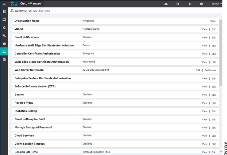
Use the Settings screen to view the current settings and configure the setting for Cisco vManage parameters, including the organization name, vBond orchestrator's DNS name or IP address, certificate settings, and statistics collection.

The current setting for each item is displayed in the bar for each item, immediately following the name.
Configure Organization Name

Before you can generate a Certificate Signing Request (CSR), you must configure the name of your organization. The organization name is included in the CSR.

In public key infrastructure (PKI) systems, a CSR is sent to a certificate authority to apply for a digital identity certificate.

To configure the organization name:

  1. Click the Edit button to the right of the Organization Name bar.

  2. In the Organization Name field, enter the name of your organization. The organization name must be identical to the name that is configured on the vBond orchestrator.

  3. In the Confirm Organization Name field, re-enter and confirm your organization name.

  4. Click Save.

Note that once the control connections are up and running, the organization name bar is no longer editable.

Configure Cisco vBond DNS Name or IP Address

  1. Click the Edit button to the right of the vBond bar.

  2. In the vBond DNS/IP Address: Port field, enter the DNS name that points to the vBond orchestrator or the IP address of the Cisco vBond orchestrator and the port number to use to connect to it.

  3. Click Save.

Enable Email Notifications

You can configure the Cisco vManage to send email notifications when alarms occur on devices in the overlay network. First configure the SMTP and email recipient parameters on this screen:

  1. Click the Edit button to the right of the Email Notifications bar.

  2. In the Enable Email Notifications field, click Enabled.

  3. Select the security level for sending the email notifications. The security level can be none, SSL, or TLS.

  4. In the SMTP Server field, enter the name or IP address of the SMTP server to receive the email notifications.

  5. In the SMTP port field, enter the SMTP port number. For no security, the default port is 25; for SSL it is 465; and for TLS it is 587.

  6. In the From Address field, enter the full email address to include as the sender in email notifications.

  7. In the Reply To address, enter the full email address to include in the Reply-To field of the email. This address can be a noreply address, such as noreply@cisco.com.

  8. To enable SMTP authentication to the SMTP server, click Use SMTP Authentication. Enter the username and password to use for SMTP authentication. The default user email suffix is appended to the username. The password that you type is hidden.

  9. Click Save.

Configure alarms that trigger emails by clicking the Email Notifications button on the Monitor > Alarms screen.

Configure Controller Certificate Authorization Settings

Signed certificates are used to authenticate devices in the overlay network. Once authenticated, devices can establish secure sessions between each other. It is from the Cisco vManage that you generate these certificates and install them on the controller devices—Cisco vBond orchestrators,Cisco vManage, and Cisco vSmart controllers. You can use certificates signed by Symantec, or you can use enterprise root certificates.

The controller certification authorization settings establish how the certification generation for all controller devices will be done. They do not generate the certificates.

You need to select the certificate-generation method only once. The method you select is automatically used each time you add a device to the overlay network.

To have the Symantec signing server automatically generate, sign, and install certificates on each controller device:

  1. Click the Edit button to the right of the Controller Certificate Authorization bar.

  2. Click Symantec Automated (Recommended). This is the recommended method for handling controller signed certificates.

  3. In the Confirm Certificate Authorization Change popup, click Proceed to confirm that you wish to have the Symantec signing server automatically generate, sign, and install certificates on each controller device.

  4. Enter the first and last name of the requestor of the certificate.

  5. Enter the email address of the requestor of the certificate. This address is required because the signed certificate and a confirmation email are sent to the requestor via email; they are also made available though the customer portal.

  6. Specify the validity period for the certificate. It can be 1, 2, or 3 years.

  7. Enter a challenge phrase.The challenge phrase is your certificate password and is required when you renew or revoke a certificate.

  8. Confirm your challenge phrase.

  9. In the Certificate Retrieve Interval field, specify how often the Cisco vManage server checks if the Symantec signing server has sent the certificate.

  10. Click Save.

To manually install certificates that the Symantec signing server has generated and signed:

  1. Click the Edit button to the right of the Controller Certificate Authorization bar.

  2. Click Symantec Manual.

  3. In the Confirm Certificate Authorization Change popup, click Proceed to manually install certificates that the Symantec signing server has generated and signed.

  4. Click Save.

To use enterprise root certificates:

  1. Click the Edit button to the right of the Controller Certificate Authorization bar.

  2. Click Enterprise Root Certificate.

  3. In the Confirm Certificate Authorization Change popup, click Proceed to confirm that you wish to use enterprise root certificates.

  4. In the Certificate box, either paste the certificate, or click Select a file and upload a file that contains the enterprise root certificate.

  5. By default, the enterprise root certificate has the following properties: To view this information, issue the show certificate signing-request decoded command on a controller device, and check the output in the Subject line. For example:

    • Country: United States

    • State: California

    • City: San Jose

    • Organizational unit: ENB

    • Organization: CISCO

    • Domain Name: cisco.com

    • Email: cisco-cloudops-sdwan@cisco.com

    vSmart# show certificate signing-request decoded
        ...
        Subject: C=US, ST=California, L=San Jose, OU=ENB, O=CISCO, CN=vsmart-uuid .cisco.com/emailAddress=cisco-cloudops-sdwan@cisco.com 
        ...
       
    To change one or more of the default CSR properties:
    1. Click Set CSR Properties.

    2. Enter the domain name to include in the CSR. This domain name is appended to the certificate number (CN).

    3. Enter the organizational unit (OU) to include in the CSR.

    4. Enter the organization (O) to include in the CSR.

    5. Enter the city (L), state (ST), and two-letter country code (C) to include in the CSR.

    6. Enter the email address (emailAddress) of the certificate requestor.

    7. Specify the validity period for the certificate. It can be 1, 2, or 3 years.

  6. Click Import & Save.

Enforce Software Version on Devices

If you are using the Cisco SD-WAN hosted service, you can enforce a version of the Cisco SD-WAN software to run on a router when it first joins the overlay network. To do so:

  1. Ensure that the software image for the desired device software version is present in the vManage software image repository:

    1. In Cisco vManage, select the Maintenance > Software Repository screen.

      The Software Repository screen opens and displays a table of software images. If the desired software image is present in the repository, continue with Step 2.

    2. If you need to add a software image, click Add New Software.

    3. Select the location from which to download the software images, either Cisco vManage, Remote Server, or Remote Server - vManage.

    4. Select an x86-based or a MIPS-based software image.

    5. Click Add to play the image in the repository.

  2. In the Administration > Settings screen, click the Edit button to the right of the Enforce Software Version (ZTP) bar.

  3. In the Enforce Software Version field, click Enabled.

  4. From the Version drop-down, select the version of the software to enforce on the device when they join the network.

  5. Click Save.

If you enable this feature on the Cisco vManage, any device joining the network is configured with the version of the software specified in the Enforce Software Version field regardless of whether the device was running a higher or lower version of Cisco SD-WAN software.

Banner

Use the Banner template for Cisco vBond Orchestrators, Cisco vManages, Cisco vSmart Controllers, Cisco vEdge devices, and Cisco IOS XE SD-WAN devices.

You can configure two different banner text strings, one to be displayed before the CLI login prompt on a Cisco SD-WAN device and the other to be displayed after a successful login to the device.

  • To configure the banner text for login screens using Cisco vManage templates, create a Banner feature template to configure PIM parameters, as described in this topic.

  • To configure a login banner for the Cisco vManage system, go to Administration > Settings.​

Configure a Banner

  1. In Cisco vManage, select the Configuration > Templates screen.

  2. In the Device tab, click Create Template.

  3. From the Create Template drop-down, select From Feature Template.

  4. From the Device Model drop-down, select the type of device for which you are creating the template.

  5. Click the Additional Templates tab located directly beneath the Description field, or scroll to the Additional Templates section.

  6. From the Banner drop-down, click Create Template. The Banner template form is displayed. The top of the form contains fields for naming the template, and the bottom contains fields for defining Banner parameters.
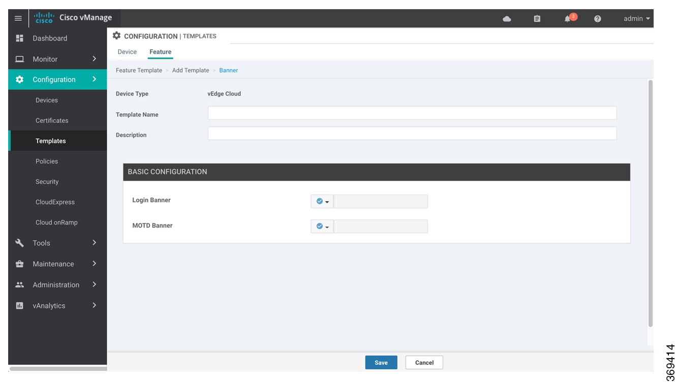
  7. In the Template Name field, enter a name for the template. The name can be up to 128 characters and can contain only alphanumeric characters.

  8. In the Template Description field, enter a description of the template. The description can be up to 2048 characters and can contain only alphanumeric characters.

    When you first open a feature template, for each parameter that has a default value, the scope is set to Default (indicated by a check mark), and the default setting or value is shown. To change the default or to enter a value, click the Scope drop-down to the left of the parameter field.

  9. To set a banner, configure the following parameters:

    Table 1. Parameters to be configured while setting a banner:

    Parameter Name

    Description

    MOTD Banner

    On a Cisco vEdge device enter message-of-the-day text to display after a successful login. The string can be up to 2048 characters long. To insert a line break, type \n.

    On a Cisco IOS XE SD-WAN device enter message-of-the-day text to display prior to the login banner. The string can be up to 2048 characters long. To insert a line break, type \n.

    Login Banner

    Enter text to display before the login prompt. The string can be up to 2048 characters long. To insert a line break, type \n.

  10. To save the feature template, click Save.

CLI equivalent:


banner{login text | motd text}

banner{login login-string | motd motd-string}

Release Information

Introduced in Cisco vManage NMS in Release 15.2.

Create a Custom Banner

To create a custom banner that is displayed after you log in to the Cisco vManage:

  1. Click the Edit button to the right of the Banner bar.

  2. In the Enable Banner field, click Enabled.

  3. In the Banner Info text box, enter the text string for the login banner or click Select a File to download a file that contains the text string.

  4. Click Save.

Enable Reverse Proxy

In a standard overlay network, vEdge routers initiate direct connections to the Cisco SD-WAN controllers—Cisco vManage and Cisco vSmart Controllers—over which they exchange control plane information. Because vEdge routers are typically located in branch sites and hence access the Cisco SD-WAN controllers over the internet, the result is that Cisco vManage and Cisco vSmart Controllers have connections directly to the internet.

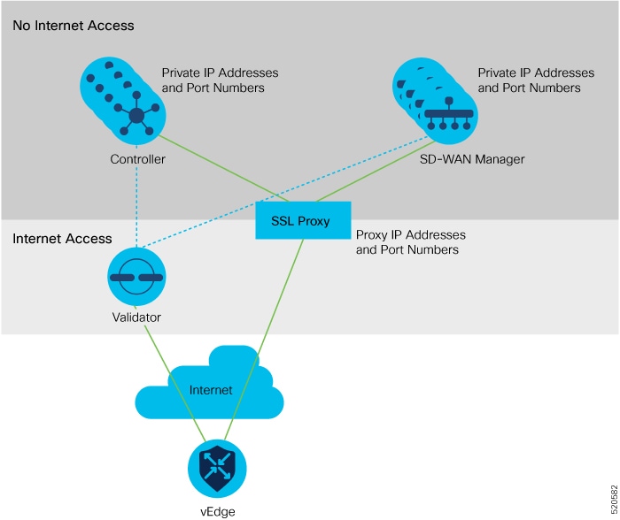
If, for security or other reasons, you do not want these devices to have direct internet connections, you can insert a reverse proxy between the Cisco SD-WAN controllers and the vEdge routers. The reverse proxy acts as an intermediary to pass control traffic between the Cisco SD-WAN controllers and the vEdge routers. So instead of communicating directly with Cisco vManage and the Cisco vSmart Controllers, the vEdge routers communicate directly with the intermediate proxy device, and the proxy device relays the traffic to and from Cisco vManage and Cisco vSmart Controller controller devices.

The following figure illustrates a reverse proxy inserted between a Cisco vEdge device and the vSmart and vManage controllers.
Enable Reverse Proxy

To enable reverse proxy services in the overlay network:

  1. Click the Edit button to the right of the Reverse Proxy bar.

  2. Click Enabled.

  3. Click Save.

To configure reverse proxy on individual Cisco vManage and Cisco vSmart Controller devices, in Cisco vManage, select Configuration > Devices and click the Controllers tab. For the desired device, click the More Actions icon to the right of the row, and click Add Reverse Proxy. Configure the private and proxy IP addresses and ports for the device.

Provision Certificates on the Proxy

For reverse proxy to work, the reverse proxy device and the vEdge routers must authenticate each other.

On the reverse proxy device you must provision a certificate that is signed by the same CA with which the Cisco SD-WAN controller's certificate is signed.

On the reverse proxy, you also need to provision the Cisco vManage certificate bundle exported form Cisco vManage. This certificate is used by the reverse proxy to verify the vEdge routers. To do this:

  1. In Cisco vManage, select the ConfigurationCertificates screen.

  2. Click Controllers in the top bar.

  3. Click Export Root Certificate in the top bar.

Configure Reverse Proxy on Controllers

To configure reverse proxy on individual Cisco vManage and Cisco vSmart Controller devices:

  1. In Cisco vManage select the ConfigurationDevices screen.

  2. Click the Controllers tab.

  3. For the desired device, click the More Actions icon to the right of the row, and click Add Reverse Proxy. The Add Reverse Proxy popup is displayed.

  4. Click Add Reverse Proxy.

  5. Configure the private IP address and port number for the device. The private IP address is the IP address of the transport interface in VPN 0. The default port number is 12346. This is the port used to establish the connections that handle control and traffic in the overlay network.

  6. Configure the proxy IP address and port number for the device, to create the mapping between the private and public IP addresses and port numbers.

  7. If the Cisco vManage or Cisco vSmart Controller has multiple cores, repeat Steps 5 and 6 for each core.

  8. Click Add.

  9. In the Security feature configuration template for Cisco vManage and the Cisco vSmart Controller, set the transport protocol to be TLS.

To display a device's private and proxy (public) IP addresses and port numbers, in the vManage Monitor ► Network screen, select the device, click Real Time, and select the Control Connections command. To display these IP address and pot numbers in the CLI, issue the show control local-properties command.

To verify the mapping between the private and proxy IP addresses and port numbers, issue the show orchestrator reverse-proxy-mapping command on the Cisco vBond Orchestrator.

In the output of the show control connections command on a vEdge router, if the Proxy column value is Yes, the Peer Public IP and Peer Public Port fields show the proxy IP address and port number, respectively, and the output indicates that the connection is the controller device is through the proxy.

Have vEdge Router Generate Certificate

After you configure reverse proxy on the overlay network controllers, any vEdge router that joins the overlay network or that is already operating in the overlay network requires a signed certificate to establish a secure connection to the proxy device. The process for generating the signed certificate is initiated automatically by the vEdge router as soon as it learns that reverse proxy is enabled in the network, and the vEdge router receives a signed certificate that it uses to establish a secure connection to the reverse proxy device.

To view the signed certificate, issue the show certificate reverse-proxy command on the vEdge router.

Collect Device Statistics

To enable or disable the collection of statistics for devices in the overlay network:

  1. Click the Edit button to the right of the Statistics Settings bar. By default, all statistics collection settings are enabled for all Cisco SD-WAN devices.

  2. To set statistics collection parameters for all devices in the network, click Disable All for the parameter you wish to disable statistics collection for. To return to the saved settings during an edit operation, click Reset. To return the saved settings to the factory-default settings, click Restore Factory Default

  3. To set statistics collection parameters for individual devices in the network, click Custom to select devices on which to enable or disable statistics collection. The Select Devices popup screen opens listing the hostname and device IP of all devices in the network. Select one or more devices from the Enabled Devices column on the left and click the arrow pointing right to move the device to the Disabled Devices column on the right. To move devices from the Disabled Devices to the Enabled Devices column, select one or more devices and click the arrow pointing left. To select all devices in the Select Devices popup screen, click the Select All checkbox in either window. Click Done when all selections are made.

  4. Click Save.

Set the Time Interval to Collect Device Statistics

To set the time interval at which vManage NMS should collect statistics for devices in the overlay network, use the Administration > Settings screen.

  1. Click the Edit button to the right of the Statistics Configuration bar. By default, statistics is collected for all Viptela devices every 30 minutes.

  2. Click the up or down arrow in the Collection Interval drop-down to change the frequency at which to collect device statistics. The minimum time you can specify is 5 minutes and the maximum is 180 minutes.

  3. Click Save.

Enable vAnalytics

  1. Open a support case with Cisco, https://mycase.cloudapps.cisco.com/case, and provide the following information:

    • Customer name

    • Organization Name (as configured in vManage)

    • Cisco Sales/SE contact

    • Approved by (customer contact)

    • Customer email

    • Approved by customer on (specify date)

    Customer approval is needed as vAnalytics collects network and application-related data (PII data), and this data is stored in the US-West cloud region in Amazon Web Services.

    After receiving this information, Cisco takes approximately 24 to 48 hours to ready the backend set up and provide the appropriate log-on credentials for vAnalytics.

    Once you receive log-on credentials for vAnalytics:
    1. Navigate to the Cisco vManage Dashboard Administration > Settings tab.
    2. Click the Edit button to the right of the vAnalytics bar.
    3. In the Enable vAnalytics field, click Enabled.
    4. Enter SSO Username and SSO Password.
    5. Check the I agree check box.
    6. Click Save.

Web Server Certificate for vManage

To establish a secure connection between your web browser and the vManage server using authentication certificates, you must generate a CSR to create a certificate, have it signed by a root CA, and then install it. To do so:

  1. Click the CSR button to the right of the Web Server Certificate bar.

  2. In the Common Name field, enter the domain name or IP address of the vManage server. For example, the fully-qualified domain name of vManage could be vmanage.org.local.

  3. In the Organizational Unit field, enter the unit name within your organization, for example, Network Engineering.

  4. In the Organization field, enter the exact name of your organization as specified by your root CA, for example, Viptela Inc.

  5. In the City field, enter the name of the city where your organization is located, for example, San Jose.

  6. In the State field, enter the state in which your city is located, for example, California.

  7. In the 2-Letter Country Code field, enter the two-letter code for the country in which your state is located. For example, the two-letter country code for the United States of America is US.

  8. From the Validity drop-down, select the validity period for the certificate.

  9. Beginning with Cisco IOS XE SD-WAN release 16.11 and Cisco SD-WAN release 19.1, in the Subject Alternative Name (SAN) DNS Names field, enter the names of DNS severs to which the certificate trust should be extended. If you enter more than one DNS server name, separate each name with a space or a comma.

  10. Beginning with Cisco IOS XE SD-WAN release 16.11 and Cisco SD-WAN release 19.1, in the Subject Alternative Name (SAN) URIs field, enter the URIs of resources to which the certificate trust should be extended. If you enter more than one URI, separate each URI with a space or a comma.

  11. Click Generate to generate the CSR.

  12. Send the CSR to your CA server to have it signed.

  13. When you receive the signed certificate, click the Certificate button to the right of the Web Server Certificate bar to install the new certificate. The View box displays the current certificate on the vManage server.

  14. Copy and paste the new certificate in the box. Or click the Import button, click Select a File to download the new certificate file, and click Import.

  15. Restart the application server.

View Web Server Certificate Expiration Date 

When you establish a secure connection between your web browser and the vManage server using authentication certificates, you configure the time period for which the certification is valid (in Step 8 in the previous section). At the end of this time period, the certificate expires. The Web Server Certificate bar shows the expiration date and time.

Starting 60 days before the certificate expires, the vManage Dashboard displays a notification indicating that the certificate is about to expire. This notification is then redisplayed 30, 15, and 7 days before the expiration date, and then daily.

Update IPS Signatures

IPS uses Cisco Talos signatures to monitor the network. Cisco recommends following this procedure to download the latest signatures.


Note

To download the signatures, vManage requires access to the following domains using port 443:

  • api.cisco.com

  • cloudsso.cisco.com

  • dl.cisco.com

  • dl1.cisco.com

  • dl2.cisco.com

  • dl3.cisco.com


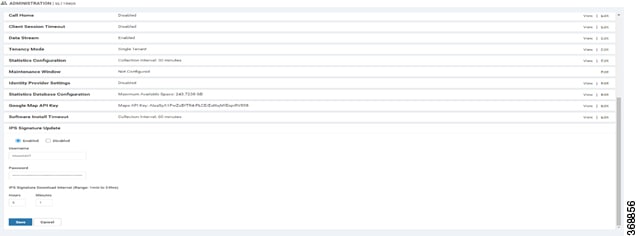
  1. In Cisco vManage, select the Administration > Settings tab in the left side panel to configure IPS Signature Update.

  2. Click on Edit to Enable/Disable and provide your Cisco.com Username and Password details to save the Policy details as shown in the following screenshot.
Manage Users using Cisco vManage

Use the Manage Users screen to add, edit, view, or delete users and user groups from Cisco vManage.

Only a user logged in as the admin user or a user who has Manage Users write permission can add, edit, or delete users and user groups from Cisco vManage.

View User Accounts and Add a User

To perform operations on a device, you configure usernames and passwords for users who are allowed to access the device. The Cisco SD-WAN software provides one standard username, admin, and you can create custom usernames, as needed. We recommend that you configure strong passwords for users.

To check vManage user accounts and the permissions:

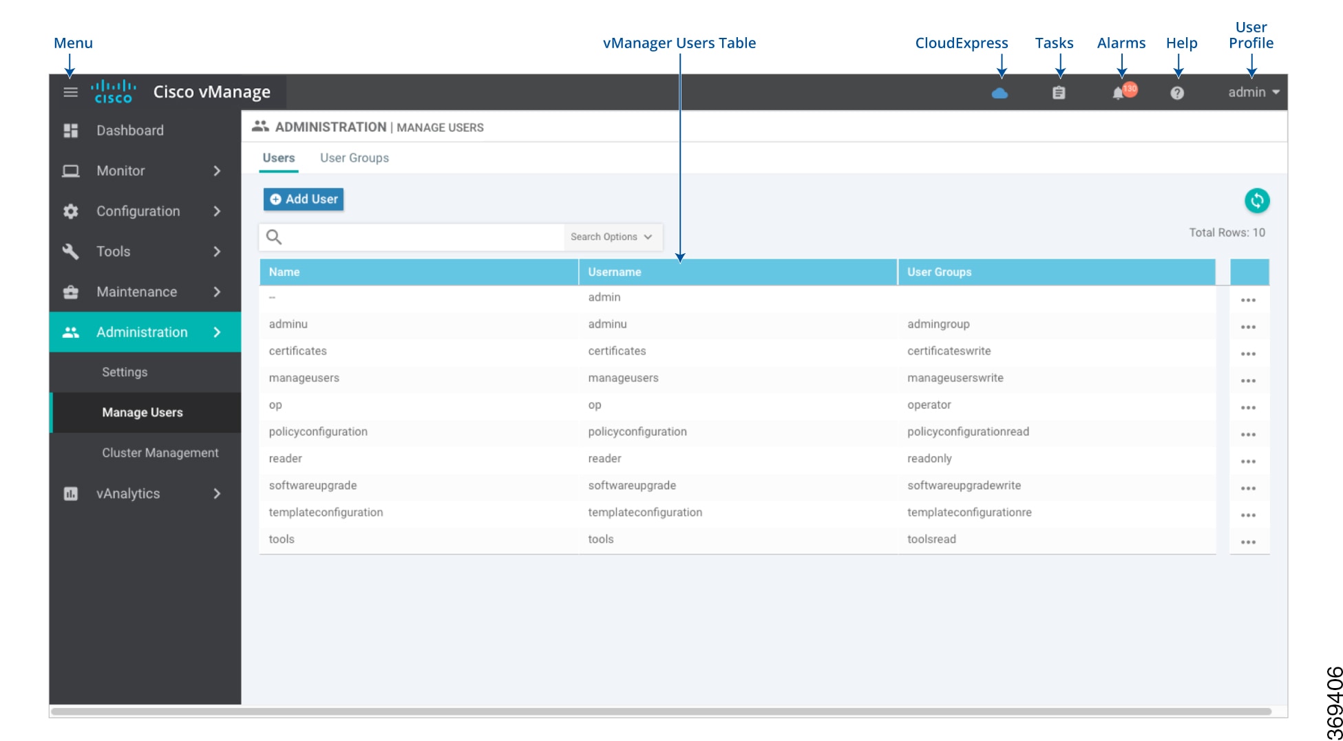
  1. In Cisco vManage, navigate to Administration > Manage Users.

  2. On the Users tab, view all users who have accounts on Cisco vManage.

  3. In the left pane, click the user name. The right pane then shows the features for which the user has read or write permission.

To add a user:

  1. On the Users tab, click Add User.

  2. In the Add User pop-up window, enter the full name, username, and password for the user. Note that uppercase characters are not allowed in usernames.

  3. From the User Groups drop-down list, select the groups that the user will be a member of.

    To edit user account information, click the More Actions icon to the right of a table row.

  4. Click Add. The user is then listed in the user table.

Delete a User

If a user no longer needs access to devices, you can delete the user. When you delete a user, that user no longer has access to the device. Deleting a user does not force log out the user if the user is logged in.

To delete a user:

  1. On the Users tab, select the user you wish to delete.

  2. Click the More Actions icon to the right of the column and click Delete.

  3. Click OK to confirm deletion of the user.

Edit User Details

Editing user details lets you update login information for a user, and add or remove a user from a user group. If you edit details for a user who is logged in, the changes take effect after the user logs out.

To edit user details:

  1. On the Users tab, select the user whose details you wish to edit.

  2. Click the More Actions icon to the right of the column and click Edit.

  3. Edit login details, and add or remove the user from user groups.

  4. Click Update.

Change User Password

You can update passwords for users as needed. We recommend that you use strong passwords.

To change a password for a user:

  1. On the Users tab, select the user whose password you wish to change.

  2. Click the More Actions icon to the right of the column and click Change Password.

  3. Enter password, and then confirm, the new password. Note that the user, if logged in, is logged out.

  4. Click Done.

Check Users Logged into a Device

  1. In Cisco vManage, navigate to Administration > Manage Users.

  2. From the Device Groups drop-down list in the left pane, select the device group to which the device belongs. A list of all the devices in the group is displayed in the left pane.

  3. Choose the options in the Sort by drop-down to sort the device list by status, hostname, system IP, site ID, or device type.

  4. Select the device from the left pane.

  5. In the right pane, click the Real Time toggle button.

  6. From the drop-down list at the top of the right pane, select Users.

Manage a User Group

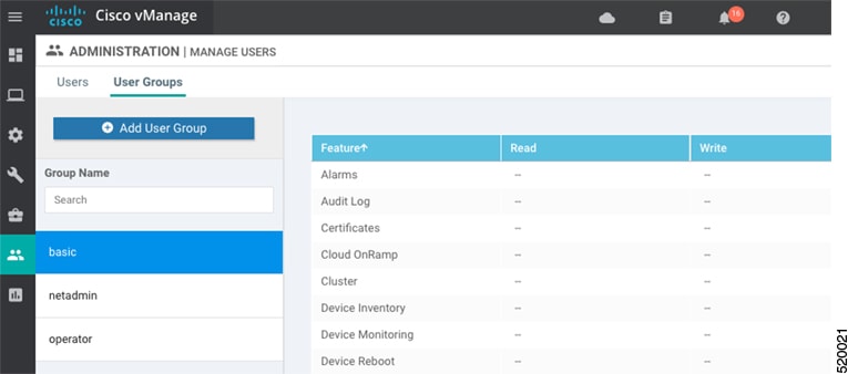
Users are placed in groups, which define the specific configuration and operational commands that the users are authorized to view and modify. A single user can be in one or more groups. The Cisco SD-WAN software provides three standard user groups, and you can create custom user groups, as needed:

  • basic—Includes users who have permission to view interface and system information.

  • netadmin—Includes the admin user, by default, who can perform all operations on the vManage NMS. You can add other users to this group.

  • operator—Includes users who have permission only to view information.

To add a user group:

  1. In Cisco vManage, navigate to Administration > Manage Users

    .
  2. On the User Groups tab, click Add User Group.

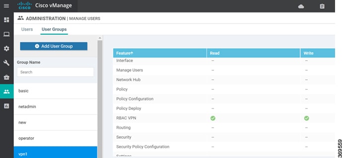
  3. In the Add User Group pop-up window, enter the user group name and select the desired read and write permissions for each feature. Note that uppercase characters are not allowed in user group names.

  4. Click OK. The user group is then listed in the left pane.

Each user group can have read or write permission for the features listed below. Write permission includes read permission.

Note: All user groups, regardless of the read or write permissions selected, can view the information displayed on the Cisco vManage Dashboard screen.

Delete a User Group

You can delete a user group when it is no longer needed. For example, you might delete a user group that you created for a specific project when that project ends.

  1. In Cisco vManage, navigate to Administration > Manage Users

    .
  2. On the User Groups tab, click the name of the user group you wish to delete. Note that you cannot delete any of the three standard user groups—basic, netadmin, and operator.

  3. Click the Trash icon.

  4. Click OK to confirm deletion of the user group.

Edit User Group Privileges

You can edit group privileges for an existing user group. This procedure lets you change configured feature read and write permissions for the user group needed.

  1. In Cisco vManage, navigate to Administration > Manage Users

    .
  2. On the User Groups tab, select the name of the user group whose privileges you wish to edit. Note that you cannot edit privileges for the three standard user groups—basic, netadmin, and operator.

  3. Click the Edit button located directly above the privilege level table, and edit privileges as needed.

  4. Click Save.

If an admin user changes the privileges of a user by changing their group, and if that user is currently logged in to the device, the user is logged out and must log back in again.

Configure User with User group

To create users with user group that is associated with the VPN group:

  1. Navigate to Administration > Manage Users from Cisco vManage. The manage Users window appears.

  2. To edit, delete, or change password for an existing user, click the Edit, Delete, or Change Password in the More Info (…) column on the right side.

  3. Click on Add User to add a new user.

  4. In the Add New User page, add Full Name, Username, Password, and Confirm Password details.

  5. In the User Group drop-down, select the user group where you want to add a user.

  6. If you want to add a User Group, click on Add User Group button.

  7. Enter the user group name in the Group Name field.

  8. Select the Read or Write checkbox that you want to assign to a user group as shown in the figure.

Cluster Management

Use the Cluster Management screen to create a vManage NMS cluster. In a vManage NMS cluster, all the cluster members communicate and work cooperatively to manage all the vBond orchestrators, vEdge routers, and vSmart controllers in the overlay network. Each vManage server can manage up to about 2,000 vEdge routers in the overlay network.

It is strongly recommended that all members of a vManage NMS cluster be located in the same data center.

Change the IP Address of the Current vManage NMS

It is recommended that you configure the IP address of the vManage server statically, in its configuration file. Configure this IP address on a non-tunnel interface in VPN 0. It is also recommended that you do not configure DHCP in VPN 512.

When you start a vManage NMS for the first time, the default IP address of the vManage server is shown as "localhost". Before you can add a new vManage NMS to a cluster, you must change "localhost" to an IP address:

  1. In the Service Configuration tab, click the Add vManage button. The Edit vManage screen opens.

  2. From the vManage IP Address drop-down list, select an IP address to assign to the vManage server.

  3. Specify a username and password for the vManage server.

  4. Click Update.

The vManage server automatically reboots and displays the Cluster Management screen.

Add a vManage NMS

To add a new vManage NMS to the cluster:

  1. In the Service Configuration tab, click the Add vManage button. The Add vManage screen opens.

  2. Enter the IP address of the vManage NMS you are adding to the cluster.

  3. Specify the username and password for the new vManage server.

  4. Select the services to run on the vManage server. You can select from the services listed below. Note that the Application Server field is not editable. The vManage Application Server is the local vManage HTTP web server.

    • Statistics Database—Stores all real-time statistics from all Viptela devices in the network.

    • Configuration Database—Stores all the device and feature templates and configurations for all Viptela devices in the network.

    • Messaging Server—Distributes messages and shares state among all vManage NMS cluster members.

  5. Click Add. The vManage NMS that you just added then reboots before joining the cluster.

In a cluster, it is recommended that you run at least three instances of each service.

Note: It is strongly recommended that the IP addresses of all members of the vManage cluster be in the same subnet.

Note: The members of a vManage cluster rely on timestamps to synchronize data and to track device uptime. For this time-dependent data to remain accurate, you cannot change the clock time on any one of the vManage servers of the cluster after you create the cluster.

Configure the Statistics Database

To configure the statistics database, which stores all real-time statistics from the local vManage NMS:

  1. In the Service Configuration tab, click the Statistics Database Configuration button. The Statistics Database Configuration screen opens. The top of the screen specifies the maximum space available for the database.

  2. For each Statistics Type field, assign an the amount of storage to allocate, in gigabytes (GB). The total value of all fields cannot exceed the maximum available space.

  3. Click Update.

vManage NMS updates the storage allocations you have assigned once a day, at midnight.

View Statistics Database Space Usage

To view the amount of space available and utilized for the statistics database on the local vManage NMS, in the Service Configuration tab, click the Statistics Database Configuration button. The Statistics Database Configuration screen opens. The top of the screen shows the maximum space available for the database and the total amount of space currently being utilized. The table on this screen shows, for each statistics type, the disk space currently being utilized.

View vManage Service Details

To view detailed information about the services running on a vManage NMS:

  1. In the Service Configuration tab, click on the hostname of the vManage server. The IP Address screen opens, with the vManage Details tab selected. This screen displays the process IDs of all the vManage services that are enabled on the vManage NMS.

  2. Click Cluster Management in the breadcrumb in the title bar to return to the Cluster Management screen.

View Devices Connected to a vManage NMS

To view a list of devices connected to a vManage NMS:

  1. In the Service Configuration tab, click on the hostname of the vManage server. The IP Address screen opens with the vManage Details tab selected.

  2. Click the Connected Device tab to view a detailed list of all devices connected to the vManage NMS.

Alternatively:

  1. In the Service Configuration tab, for a vManage NMS, click the More Actions icon to the right of its row.

  2. Click Device Connected.

    If a device is connected to Cisco vManage from a cluster, ensure that you do not configure the data stream hostname to the Cisco vManage system IP address. However, you can configure the management IP address on VPN 512 or internet public IP address on VPN 0. To know more about data stream troubleshooting tools, see Data Stream Troubleshooting Tools FAQ.

Edit a vManage NMS

To set the login credentials for a vManage NMS server, use the vManage Administration ► Cluster Management screen:

  1. In the Service Configuration tab, for a vManage NMS, click the More Actions icon to the right of its row and click Edit. The Edit vManage screen opens.

  2. In the vManage IP Address box, select the IP address to edit.

  3. Enter the username and password, and edit the cluster services provided by that vManage NMS.

  4. Click Update.

Remove a vManage NMS from the Cluster

  1. In the Service Configuration tab, for a vManage NMS, click the More Actions icon to the right of its row and click Remove. The Remove vManage dialog box opens.

  2. Enter the username and password to confirm removal of the device from the network.

  3. Click Remove.

The vManage NMS is removed from the cluster, the device is invalidated, and the certificates for that device are deleted. The remaining members in the cluster re-balance the NMS services.

View Available Cluster Services

To view the services that are available and reachable on all members in the vManage NMS cluster, click the Service Reachability tab.

Integration Management

Guidelines to Integrate with Cisco ACI

The general steps that you perform in Cisco vManage to configure the integration are:

  1. Verify that Cisco ACI has registered the desired controller as a partner with a Cisco vSmart Controller, as described in the procedure, Verify Cisco ACI Registration.

  2. Attach devices to the Cisco vSmart Controller, as described in the Map ACI Sites section.

The following guidelines apply when integrating Cisco vManage with Cisco ACI:

  • Only new Cisco IOS XE SD-WAN deployments support this integration.

  • Make sure that any devices to which the Cisco APIC sends policies do not have any application-aware routing policies configured for them.

  • Make sure each device to which the Cisco APIC sends policies has an attached template.

  • Before you begin the integration, use the CLI policy builder to create a centralized policy and activate it by using the Cisco vManage policy builder.

  • Before you apply WAN SLA policies, establish a connection between the Cisco vSmart Controller and the Cisco APIC. For instructions, see Cisco ACI and Cisco IOS XE SD-WAN Integration.

  • Before you attach devices, configure Cisco ACI for this integration.

Verify Cisco ACI Registration

After you configure Cisco ACI for integration with Cisco vManage, perform the following steps in the Cisco vManage to verify that Cisco ACI has registered the desired controller as a Cisco vManage partner:

Procedure


Step 1

In Cisco vManage, select Administration > Integration Management.

The Integration Management page displays.

Step 2

On the Integration Management page, verify that ACI Partner Registration appears in the Description for the controller to which the Cisco APIC is to send policies.


Map ACI Sites

Mapping ACI sites designates the controller devices to which the policies from Cisco APIC apply.

Before you begin, review the guidelines in the Guidelines to Integrate with Cisco ACI section.

To attach devices to a controller, follow these steps:

Procedure


Step 1

In Cisco vManage, select Administration > Integration Management.

The Integration Management page displays.

Step 2

Click the More Actions icon to the right of the row for the applicable site and select Attach Devices.

Step 3

In the Available Devices column on the left, select a group and search for one or more devices, select a device from the list, or click Select All.

Step 4

Click the arrow pointing right to move the device to the Selected Devices column on the right.

To remove devices from the Selected Devices column, in that column select a group and search for one or more devices, select a device from the list, or click Select All, and then click the arrow pointing left.

Step 5

Click Attach.


Unmap ACI Sites

Unmapping ACI sites stops Cisco APIC policies from being applied to the unmapped devices.

To detach devices from a controller, follow these steps:

Procedure


Step 1

In Cisco vManage, select Administration > Integration Management.

The Integration Management page displays.

Step 2

Click the More Actions icon to the right of the row for the applicable site and select Detach Devices.

Step 3

In the Available Devices column on the left, select a group and search for one or more devices, select a device from the list, or click Select All.

Step 4

Click the arrow pointing right to move the device to the Selected Devices column on the right.

To remove devices from the Selected Devices column, in that column select a group and search for one or more devices, select a device from the list, or click Select All, and then click the arrow pointing left.

Step 5

Click Detach.


Delete a Controller

If you want to remove a controller as a partner with Cisco ACI, we recommend that you remove its registration by using Cisco ACI instead of deleting it in Cisco vManage. Deleting an ACI partner from Cisco vManage automatically deletes the data prefixes and VPNs that Cisco ACI created for the partner.

Before you begin, remove from policy definitions and data prefix lists and VPN lists that ACI created and make sure that these lists are not referenced from any policy.

Procedure


Step 1

In Cisco vManage, select Administration > Integration Management.

The Integration Management page displays.

Step 2

Detach all devices that are attached to the controller.

For instructions, see the Detach Devices from a Controller section.

Step 3

Click the More Actions icon to the right of the row for the applicable site and select Delete Controller.


Configure Disaster Recovery

Table 2. Feature History
Feature Name Release Information Feature Description

Disaster Recovery for Cisco vManage

Cisco SD-WAN Release 19.2.1

This feature helps you configure Cisco vManage in an active or standby mode to counteract hardware or software failures that may occur due to unforeseen circumstances.

You want to deploy the Cisco SD-WAN controllers across two data centers, and if a data center goes down due to a disaster, you want the network to be available. Out of the three controllers that make up theCisco SD-WAN solution, vManage is the only one that is stateful and cannot be deployed in an active/active mode. The goal of the disaster recovery solution is to deploy vManage across two data centers in some sort of primary/secondary mode.

The disaster recovery option provides automatic failover of the primary cluster to the secondary cluster. Data is replicated from the primary cluster to the secondary cluster.

There are two available disaster recovery options:

  • Manual—If you want to make the clusters active, you can do it manually rather than having the arbitrator do the switchover. You can specify the switchover threshold.

  • Automated —Arbitrator does the monitoring of the cluster and performs the necessary action.

    A highly available Cisco SD-WAN network contains three or more vManage NMSs in each domain. This scenario is referred to as a cluster of vManage NMSs, and each vManage NMS in a cluster is referred to as a vManage instance.

Architecture Overview

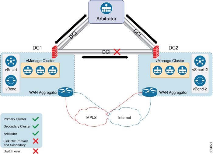
The following diagram describes the high-level architecture of the disaster recovery solution.

The arbitrator is an additional vManage cluster that runs in arbitrator mode. The arbitrator monitors the health of the primary and the secondary clusters and performs the necessary actions.

Prerequisites

Prior to configuring disaster recovery, make sure you have met the following requirements:

  • You must have two vManage clusters with three nodes in each cluster. If automated recovery option is selected, then another vManage node is required.

  • You must be able to reach the primary and the secondary cluster using HTTPS on a transport VPN (VPN 0).

  • Make sure that vSmart and vBond devices on the secondary cluster are connected to the primary cluster.

Unsupported Functionality

You cannot change the administration password after registering for disaster recovery.

Enable Disaster Recovery on Day-0:

You need to bring up two separate clusters with no devices being shared, which means do not share any vSmart, vBond, or vManage devices.

On both clusters, configure the following:

Item

Action

Secondary cluster

Bring up the secondary vManage cluster with three vManage clusters.

Arbitrator

To assign an IP address for the OOB network, navigate to Administration > Cluster Management.

Ensure reachability between the primary, secondary clusters, and arbitrator on VPN (0) using HTTPS.

Ensure reachability between the primary cluster, secondary cluster, and vBond orchestrators.

Verify after Registering for Disaster Recovery on Day-1

  • Replication from the primary cluster to the secondary cluster happens at the configured intervals.

  • Status check: Administration > Disaster Recovery.

  • Arbitrator:

    • First health check after 15 minutes. This check provides enough time for all the nodes to be up and running with the configured disaster recovery processes.

    • Health check of the primary cluster, secondary cluster, and the arbitrator every five minutes.

    • Check the /var/log/nms/vmanage-server.log for the status information on the arbitrator cluster.

Configure Disaster Recovery

  1. From the Cisco vManage dashboard, select Administration > Disaster Recovery.

  2. On the Administration > Disaster Recovery page, select Manage Disaster Recovery.

  3. To configure primary and secondary cluster, on the vManage Disaster Recovery screen, select an IP address for any vManage node within the respective cluster.

    If a cluster is behind a load balancer, specify the IP address of the load balancer.

  4. Specify the following: Start Time, Replication Interval, and Delay Threshold for replicating data from the primary to the secondary cluster.

    The default value for Delay Threshold is 30 minutes.

    The default value for Replication Interval is 15 minutes.

  5. Click Administration > Disaster Recovery, and for Cluster 2 (Secondary), click Make Primary.

    It can take 10 to 15 minutes to push all changes from all the devices.

  6. You can also decide to pause disaster recovery, pause replication, or delete your disaster recovery configuration.

    After disaster recovery is configured and you have replicated data, you can view the following:

    • when your data was last replicated, how long it took to replicate, and the size of the data that was replicated.

    • when the primary cluster was switched over to the secondary cluster and the reason for the switchover.

    • the replication schedule and the delay threshold.

Disaster Recovery Striking the Primary Data Center

  • Switchover happens only when all the nodes in the primary data center are lost.

  • The arbitrator detects the loss of all the primary data center members and initiates switchover to the secondary data center.

  • Secondary data center updates the vBond:

    • Invalidates old vManage systems.

    • New vManage systems from the secondary data center are updated, as valid.

    • Cisco IOS XE SD-WAN devices and Cisco vEdge devices reach vBond after losing control connections.

    • Cisco IOS XE SD-WAN devices and Cisco vEdge devices start forming control connections with the new valid vManage systems.

Troubleshooting Tips

If disaster recovery registration fails, verify the following:

  • Reachability to the vBond orchestrator from all cluster members on the secondary cluster.

  • Reachability between the secondary cluster, primary cluster, and the arbitrator on the transport interface (VPN 0).

  • Check that you have the correct username and password.

If disaster recovery registration fails due to arbitrator reachability, check the following:

  • You must configure the arbitrator in cluster mode. Navigate to Administration > Cluster Management, and add a vManage as the arbitrator.

  • If the IP address is not assigned to the correct arbitrator, log on to the arbitrator cluster and do the following:

    • Navigate to Administration > Cluster Management.

    • Edit the vManage.

    • Select the correct IP address from the drop-down list and save the configuration.

    The disaster recovery consul process uses this IP address for disaster recovery communication. This is set once you configure the vManage in cluster mode.

Configure and Manage VPN Groups

To configure VPN Groups:

  1. Navigate to Administration > VPN Groups in Cisco vManage. The following web page displays with the list of segments that are configured.

  2. To edit or delete an VPN group, click the Edit or Delete in the More Info (…) column on the right side.

  3. To view the existing VPN in the dashboard, click on View Dashboard in the More Info column. The VPN Dashboard displays the device details of the VPN device configured.

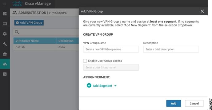
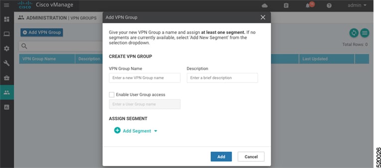
  4. To add new VPN group, click Add Group. Add VPN Group window appears.

  5. In the Create VPN Group pane, Enter VPN group name in the VPN Group Name field.

  6. Enter a brief description of the VPN in the Description field.

  7. Enable the user group access checkbox and enter the User Group Name.

  8. In the Assign Segment pane, click on Add Segment drop-down to add new or existing segment to the VPN group.

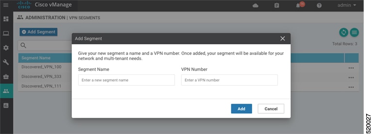
  9. Enter the Segment Name and VPN Number in the respective fields.

  10. Click Add to add the configure VPN group to a device.

Configure and Manage VPN Segments

To configure VPN Segments:

  1. Navigate to Administration > VPN Segments in Cisco vManage. The following web page displays with the list of segments that are configured.

  2. To edit or delete an existing segment, click the Edit or Delete in the More Info (…) column on the right side.

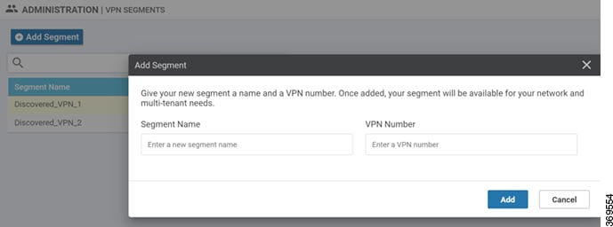
  3. To add new segment, click Add Segment. Add Segment window appears.

  4. Enter the name of the segment in the Segment Name field.

  5. Enter the number of VPNs you want to configure in VPN Number field.

  6. Click Add to add a new segment.