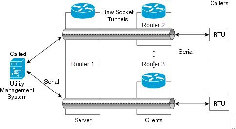
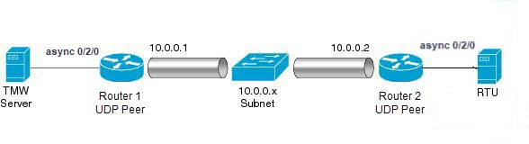
Raw socket

Raw socket

Table 1. Feature history

Feature name

Release information

Description

Raw socket

Cisco IOS XE Catalyst SD-WAN Release 17.18.1a

Cisco Catalyst SD-WAN Manager Release 20.18.1

You can transport serial data across your IP networks by configuring TCP or UDP options through configuration groups on supported Cisco rugged routers.

Raw socket

Raw socket transports serial data through an IP network. This feature enables the transportation of Supervisory Control and Data Acquisition (SCADA) data from Remote Terminal Units (RTUs). It serves as an alternative to the Block Serial Tunnel (BSTUN) protocol.

Raw Socket Transport uses either TCP or UDP as the transport protocol. You can configure an interface to use one protocol at a time, but not both simultaneously. TCP transport suits control applications that require acknowledged and sequenced data delivery. For latency-sensitive applications, such as line SEL relays, UDP transport delivers serial data faster than TCP.

Raw Socket Transport provides the following support for the asynchronous serial interface:

  • It uses TCP as the transport protocol and includes a built-in auto TCP connection retry mechanism.

  • It supports up to 32 TCP sessions.

  • You can configure the interface as a server, a client, or both.

  • It allows one server interface and multiple clients.

  • It provides VRF-awareness, enabling the router to send Raw socket transport traffic to a server host connected through a Virtual Routing and Forwarding (VRF) interface.

TCP transport

TCP raw socket transport uses a client-server model. At most one server and multiple clients can be configured on a single asynchronous serial line. In client mode, the IR1800 can initiate up to 32 TCP sessions to raw socket servers, which can be other IR1800 routers or third-party devices. The following figure shows a sample raw socket TCP configuration. In this example, serial data is transferred between RTUs and a utility management system across an IP network that includes several IR1800 routers. One IR1800 router (Router 1) acts as a raw socket server, listening for TCP connection requests from the other IR1800 routers (Router 2 and Router 3), which are configured as raw socket clients. A raw socket client receives streams of serial data from the RTUs and accumulates this data in its buffer, then places the data into packets, based on user-specified packetization criteria. The raw socket client initiates a TCP connection with the raw socket server and sends the packetized data across the IP network to the raw socket server, which retrieves the serial data from the packets and sends it to the serial interface, and on to the utility management system.


Note


When you configure the router's serial link interface as a server, the client router's serial link interface acts as its peer, and vice versa.


UDP transport

UDP transport uses a peer-to-peer model. Multiple UDP connections can be configured on an asynchronous serial line.

The following figure shows a sample raw socket UDP configuration. In this example, serial data is transferred between RTUs and a utility management system across an IP network that includes two routers (Router 1 which is an IR1800 and Router 2 which is an IR807) that are configured as raw socket UDP peers.

In this example, the raw socket UDP peer receives streams of serial data from the RTUs and accumulates this data in its buffer, then places the data into packets, based on user-specified packetization criteria. The raw socket UDP peer sends the packetized data across the IP network to the raw socket peer at the other end, which retrieves the serial data from the packets and sends it to the serial interface, and on to the utility management system.

Serial data processing

When the default serial protocol, Asynchronous Communication Protocol, is used, the IR1800 packetizes streams of serial data received by a raw socket peer based on the following criteria:

  • Packet length – You can specify a packet length that prompts the IR1800 to transmit the serial data to the peer. Once the IR1800 collects this amount of data in its buffer, it packetizes the accumulated data and forwards it to the raw socket peer.

  • Packet-timer value – The IR1800 uses the packet timer to determine how long to wait for the next character in a stream. If the IR1800 does not receive a character before the timer expires, it packetizes the data accumulated in its buffer and sends it to the raw socket peer.

  • Special character – You can specify a character that triggers the IR1800 to packetize the data in its buffer and forward it to the raw socket peer. When the IR1800 detects the special character (such as a CR/LF), it packetizes the accumulated data and sends it to the raw socket peer.

VRF-aware raw sockets

The VRF-aware raw socket transport feature enables you to isolate raw socket traffic using a VRF for efficient management and control of serial data. After configuring a VRF, you can associate the serial interface configured for raw socket transport with the VRF.

Restrictions for raw sockets

Firewalls in the network typically block UDP traffic. If the network includes such firewalls, configure pinholes to allow the Raw Socket UDP traffic.

Supported devices for raw sockets

  • Cisco Catalyst IR1800 Rugged Series Routers

  • Cisco Catalyst IR1101 Rugged Series Routers

  • Cisco Catalyst IR8340 Rugged Series Routers

Configure raw socket without VRF using a configuration group

Follow these steps to configure a raw socket feature without VRF.

Procedure


Step 1

From the Cisco SD-WAN Manager menu, click Configuration > Configuration Groups.

Step 2

Under the Transport and Management Profile, create or edit an existing transport profile.

Step 3

Click Add New Feature and select Transport VPN to create a Transport VPN feature.

Step 4

In the Transport VPN section, click the + icon and select Raw Socket.

Step 5

Click Add New from the drop-down menu in the Raw Socket section.

Step 6

Configure the raw socket parameters.

Step 7

Click Save.

Table 2. Raw socket

Field

Description

Loopback configuration

You can enable or disable the loopback configuration. Note that loopback is supported only on Cisco Catalyst IR8340 rugged series routers.

Interface name

Enter a name for the interface.

Packet length

Specify the length of the packet.

Packet time

Define the time duration to send packets.

Special character

Defines a specific character that triggers the router to send all buffered data to the raw socket peer.

Encapsulation

Choose TCP or UDP as the protocol to encapsulate and transport serial data.

If you select TCP, configure the following options:

  • Set the local port.

  • Specify the local IP.

  • Choose the TCP mode.

  • Configure any advanced TCP options as needed.

If you select UDP, configure the relevant UDP connection fields.


Configure a raw socket with VRF using a configuration group

Follow these steps to configure a raw socket feature with VRF.

Procedure


Step 1

From the Cisco SD-WAN Manager menu, choose Configuration > Configuration Groups.

Step 2

Under the Service Profile, create or edit an existing service profile.

Step 3

Click Add New Feature and select ServiceVPN to create a Service VPN feature.

Step 4

In the Service VPN section, click the + icon and select Raw Socket.

Step 5

Click Add New from the drop-down list in the Raw Socket section.

Step 6

Configure the raw socket parameters.

Step 7

Click Save.

Table 3. Raw socket

Field

Description

Loopback configuration

You can enable or disable the loopback configuration. Note that loopback is supported only on Cisco Catalyst IR8340 rugged series routers.

Interface name

Enter a name for the interface.

Packet length

Specify the length of the packet.

Packet time

Define the time duration to send packets.

Special character

Defines a specific character that triggers the router to send all buffered data to the raw socket peer.

Encapsulation

Choose TCP or UDP as the protocol to encapsulate and transport serial data.

If you select TCP, configure the following options:

  • Set the local port.

  • Specify the local IP.

  • Choose the TCP mode.

  • Configure any advanced TCP options as needed.

If you select UDP, configure the relevant UDP connection fields.


Monitor a raw socket

Follow these steps to monitor a raw socket.

  1. From Cisco SD-WAN Manager menu, choose Monitor > Devices.

  2. Select a supported rugged series router.

  3. Click Real Time in the left pane.

  4. From the Device options drop-down list, select relevant raw socket options.

Monitor a raw socket using the CLI

Use the following commands to monitor raw socket sessions and statistics on a device.

Raw socket sessions

The following is a sample output of the show raw-socket udp sessions command:
device# show raw-socket udp sessions
 UDP Sessions 
Interface   tty/(Idx)  vrf_name  socket   mode      local_ip_addr  local_port    dest_ip_addr  dest_port   up_time     idle_time/timeout
   0/3/0    74            0      client  15.1.1.1      15001        15.1.1.2       15002                  00:00:14       00:00:14/300sec
The following is a sample output of the show raw-socket tcp sessions command:
device# show raw-socket tcp sessions 
TCP Sessions 
Interface   tty/(Idx) vrf_name   socket    mode       local_ip_addr  local_port    dest_ip_addr  dest_port    up_time     idle_time/timeout
 As0/3/0   74           0         server   15.1.1.1    15001          listening   
 0/3/0      74          1         server   15.1.1.1    15001           15.1.1.2    15002                      00:00:41    00:00:41/300sec

The following is a sample output of the show raw-socket udp sessions local command:

device# show raw-socket udp sessions local 
Locally configured UDP client State 
Interface  tty  dest_ip    dest_port  local_ip    local_port  state
0/3/0      74   15.1.1.2    15002     15.1.1.1      15001      UP  

The following is a sample output of the show raw-socket tcp sessions local command:

device1# show raw-socket tcp sessions local 
Locally configured TCP client State
Interface  tty  dest_ip    dest_port  local_ip   local_port  state
0/2/0      26   15.1.1.1    15001     15.1.1.2     15002      UP  

Note


The show raw-socket tcp session local command is supported exclusively on a client device.


Raw socket statistics

The following is a sample output of the show raw-socket udp statistics command:
device# show raw-socket udp statistics 
UDP-Serial Statistics 
Interface  idx     vrf_name             sessions      udp_in_bytes         udp_out_bytes   udp_to_tty_frames    tty_to_udp_frame
As0/3/0    74        1                   0                    0                   0                    0

The following is a sample output of the show raw-socket tcp statistics command:

device# show raw-socket tcp statistics 
TCP-Serial Statistics
Interface  idx    vrf_name  sessions tcp_in_bytes   tcp_out_bytes   tcp_to_tty_frames    tty_to_tcp_frames
  As0/3/0   74    1             0                    0                   0                    0