Cisco Catalyst SD-WAN Validator Redundancy
The Cisco SD-WAN Validator performs two key functions in the Cisco Catalyst SD-WAN overlay network:
-
Authenticates and validates all Cisco SD-WAN Controllers and routers that attempt to join the Cisco Catalyst SD-WAN network.
-
Orchestrates the control plane connections between the Cisco SD-WAN Controllers and routers, thus enabling Cisco SD-WAN Controller and routers to connect to each other in the Cisco Catalyst SD-WAN network.
The Cisco SD-WAN Validator runs as a VM on a network server.
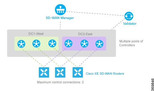
Having multiple Cisco SD-WAN Validators ensures that one of them is always available whenever a Cisco device such as a router or a Cisco SD-WAN Controller is attempting to join the network.
Configuration of Redundant Cisco Catalyst SD-WAN Validators
A vEdge Cloud router learns that it is acting as a Cisco SD-WAN Validator from its configuration. In the system vbond configuration command, specify the local IP address of the Cisco SD-WAN Validator and include the local keyword. Other Cisco IOS XE Catalyst SD-WAN devices use the system vbond configuration command without the local keyword to specify the IP address or DNS hostname of the Cisco SD-WAN Validator that those devices can connect to in order to join the overlay network and discover the other control components to establish control connections with
On Cisco SD-WAN Controllers, Cisco SD-WAN Managers and Cisco IOS XE Catalyst SD-WAN devices, when the network has only a single Cisco SD-WAN Validator, you can configure the Cisco SD-WAN Validator either as an IP address or as a host name (such as vbond.cisco.com) using the system vbond command. When the network has two or more Cisco SD-WAN Validators and they must all be reachable, you should use a DNS host name to specify the Cisco Catalyst SD-WAN Validators. If the DNS name resolves to multiple IP addresses, the Cisco IOS XE Catalyst SD-WAN device tries each Cisco Catalyst SD-WAN Validator address sequentially until it forms a successful connection.
Note that even if your Cisco Catalyst SD-WAN network has only a single Cisco SD-WAN Validator, it is recommended as a best practice that you specify a DNS host name rather than an IP address in the system vbond configuration command, because this results in a scalable configuration. Then, if you add additional Cisco SD-WAN Validators to your network, you do not need to change the configurations on any of the routers or other devices in your network.
 Note |
When configuring redundant Cisco SD-WAN Validators, ensure the following:
|
Recovering from a Cisco Catalyst SD-WAN Validator Failure
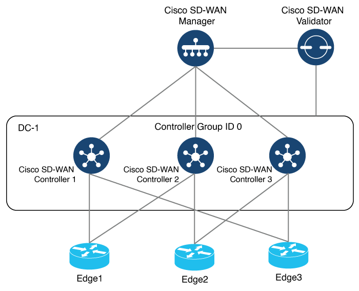
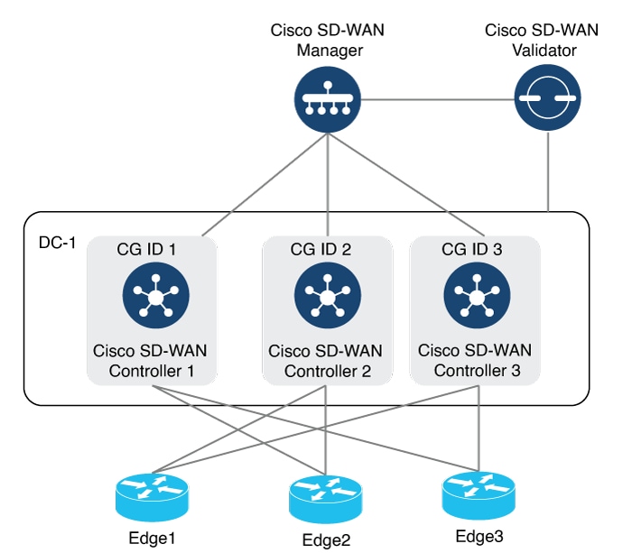
In a network with multiple Cisco SD-WAN Validators, if one of them fails, the other Cisco SD-WAN Validators simply continue operating and are able to handle all requests by Cisco devices to join the network. From a control plane point of view, each Cisco SD-WAN Validator maintains permanent DTLS connections to each of the Cisco SD-WAN Controllers in the network.
Note however, that there are no connections between the Cisco SD-WAN Validators themselves. As long as one Cisco SD-WAN Validator is present in the domain, the Cisco Catalyst SD-WAN network is able to continue operating without interruption, because Cisco SD-WAN Controllers and routers are still able to locate each other and join the network.
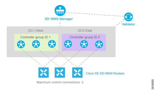
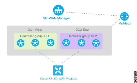
Because Cisco SD-WAN Validators never participate in the data plane of the overlay network, the failure of any Cisco SD-WAN Validator has no impact on data traffic. Cisco SD-WAN Validators communicate with routers when the routers are first joining the network. The joining router establishes a transient DTLS connection with a Cisco SD-WAN Validator to learn the IP address of a Cisco SD-WAN Controller. When the Cisco IOS XE Catalyst SD-WAN device configuration lists the Cisco SD-WAN Validator address as a DNS name, the router tries each of the Cisco SD-WAN Validators in the list, one by one, until it is able to establish a DTLS connection. This mechanism allows a router to always be able to join the network, even after one of a group of Cisco SD-WAN Validators has failed.
 Feedback