Configuring Collapsed Forwarding

This module contains the following topics:

Overview of Collapsed Forwarding

Cisco multi-switch edge (MSE) solution leverages the capabilities of the Cisco NCS 6000 series router to host multiple logical SDRs which can act as core or edge routers based on how the SDRs are configured.

The following figure specifies all the possible topologies supported by the Cisco MSE solution.

Figure 1. Supported Topologies by Cisco MSE


  • Topology T1-In this topology, all the PE SDRs converge to a common core router P1 to achieve statistical multiplexing gain.

  • Topology T2- This topology is to support redundancy at the service provider edge (dual homing) or can be also used for load balancing.

  • Topology T3 - In this topology, the service edge router converges to the external core router, outside the MSE.

  • Topology T4 - In this topology, external edge router converges to the core router inside the MSE.

  • Topology T5 - This topology is used for edge router connectivity for terminating the traffic without going to the core internal router.

  • Topology T6 - This topology is to support core router redundancy. In case P1 router goes down, P2 as redundant router runs with the same configuration.

For forwarding traffic from one SDR to another SDR, the existing solution was to connect the SDRs using external cables and ports. This approach is not cost effective for the service providers since it reduces the availability of ports for services. To overcome this issue, Cisco MSE solution uses another approach known as collapsed forwarding.

In collapsed forwarding, inter SDR traffic is handled by the internal fabric itself without requiring the external cables. A newly created SDR interface functions as a point-to-point virtual interface, connecting SDR routers in the system. This virtual interface that connects two SDRs to each other is known as cross SDR interconnect (CSI) interface.

Supported Features and Restrictions

This section provides information about the supported features and restrictions for collapsed forwarding configuration.

  • The CSI interface is a point-to-point interface that can be configured with IPv4 or IPv6 address.

  • Only routing protocols, MPLS, and multicast can be configured over the CSI interface.

  • Explicit Binding SID over CSI Interfaces is supported.

    For more information, refer to the "Configure SR-TE Policies" chapter in the Segment Routing Configuration Guide for Cisco NCS 6000 Series Routers.

  • BGP Egress Peer Engineering (EPE) over CSI interfaces is supported. This support allows a BGP neighbor established over a CSI interface to be allocated a BGP Egress Peer Engineering (EPE) segment.

    For more information, refer to the "Configure Segment Routing for BGP" chapter in the Segment Routing Configuration Guide for Cisco NCS 6000 Series Routers.

  • MPLS Entropy Label Decapsulation on Egress CSI Interfaces is supported. For more information, see MPLS Entropy Label Decapsulation on Egress CSI Interfaces.

  • IPv4 and IPv6 egress ACLs are not supported on CSI interfaces.

  • QoS and NetFlow are not supported over the CSI interface.

  • ACL based forwarding, ACL logging, and per interface ACL statistics are not supported on CSI interfaces.

  • Sub interfaces of VLANs for CSI interface is not supported.

  • For a system, only up to 15 CSI interfaces are supported.

Configuring Collapsed Forwarding

Configuring collapsed forwarding includes the following steps.

  1. Create named SDRs using the system administration configuration mode.

  2. Configure the CSI interface using the system administration configuration mode.

  3. Assign the IP addresses for the CSI interface on the required SDRs from XR configuration mode.

  4. Configure the routing protocols between SDR1 and SDR2 over the CSI interface.

Example: Creating Named SDRs

This example shows how to create named SDRs. In this example, two named SDRs, SDR1 and SDR2 are created and RP resources and line cards are allocated to the SDRs.

sysadmin-vm:0_RP0(config)# sdr sdr1
sysadmin-vm:0_RP0(config-sdr-sdr1)# resources mgmt_ext_vlan 11
sysadmin-vm:0_RP0(config-sdr-sdr1)# resources card-type RP 
sysadmin-vm:0_RP0(config-card-type-RP)#	vm-memory 11
sysadmin-vm:0_RP0(config-card-type-RP)#	vm-cpu	4
sysadmin-vm:0_RP0(config-card-type-RP)# location 0/RP0 
sysadmin-vm:0_RP0(config-location-0/RP0)# location 0/RP1 
sysadmin-vm:0_RP0(config-location-0/RP1)# exit
sysadmin-vm:0_RP0(config-sdr-sdr1)# location 0/0
sysadmin-vm:0_RP0(config-sdr-sdr1)# commit
sysadmin-vm:0_RP0(config)# sdr sdr2
sysadmin-vm:0_RP0(config-sdr-sdr2)# resources mgmt_ext_vlan 12
sysadmin-vm:0_RP0(config-sdr-sdr2)# resources card-type RP 
sysadmin-vm:0_RP0(config-card-type-RP)#	vm-memory 11
sysadmin-vm:0_RP0(config-card-type-RP)#	vm-cpu	4
sysadmin-vm:0_RP0(config-sdr-sdr2)# location 0/RP0
sysadmin-vm:0_RP0(config-location-0/RP0)# location 0/RP1 
sysadmin-vm:0_RP0(config-location-0/RP1)# exit
sysadmin-vm:0_RP0(config-sdr-sdr2)# location 0/1
sysadmin-vm:0_RP0(config-sdr-sdr2)# commit
sysadmin-vm:0_RP0# config
sysadmin-vm:0_RP0(config)# console attach-sdr location 0/RP0 tty-name console1 sdr-name SDR1
sysadmin-vm:0_RP0(config)# console attach-sdr location 0/RP1 tty-name console1 sdr-name SDR1
sysadmin-vm:0_RP0(config)# console attach-sdr location 0/RP0 tty-name console2 sdr-name SDR2
sysadmin-vm:0_RP0(config)# console attach-sdr location 0/RP1 tty-name console2 sdr-name SDR2
sysadmin-vm:0_RP0(config)# commit

For detailed information about configuring named SDRs, see Setup Console Access for Named-SDR.

Example: Configuring the CSI Interface
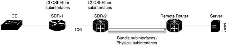
This example shows how to configure the CSI interface between two SDRs. When you perform this task, a single point-to-point link is created with one endpoint in SDR1 (called csi1 in SDR1) and the other endpoint in SDR2 (also called csi1 in SDR2). You can configure up to 15 CSI interfaces and the CSI-ID can be a number from 1 to 15.

sysadmin-vm:0_RP0(config)# connect sdr sdr1 sdr2 csi-id 1 

Example: Configuring IP addresses on the CSI Interfaces

Once the CSI interface is created, you need to configure IP addresses for the CSI interface on the inter connected SDRs using the XR configuration mode.

This example shows how to configure IPv4 addresses on the CSI interface on SDR1.

 
RP/0/RP0/CPU1:router(config)# interface csi 1
RP/0/RP0/CPU1:router(config-if)# ipv4 address 1.1.1.1 255.255.255.0
RP/0/RP0/CPU1:router(config-if)# exit
RP/0/RP0/CPU1:router(config)# commit 

This example shows how to configure IPv4 addresses on the CSI interface on SDR2.

RP/0/RP0/CPU2:router(config)# interface csi 1
RP/0/RP0/CPU2:router(config-if)# ipv4 address 1.1.1.2 255.255.255.0
RP/0/RP0/CPU1:router(config-if)# exit

Example: Configuring the Routing Protocols

This example shows how to configure a routing protocol over the CSI interface. In this example, IS-IS is used as the routing protocol. You need to configure IS-IS on SDR1 and SDR2.

 
RP/0/RP0/CPU1:router(config)# router isis 1
RP/0/RP0/CPU1:router(config-isis)# is-type level-2-only
RP/0/RP0/CPU1:router(config-isis)# net 49.0001.0001.0001.0001.00
RP/0/RP0/CPU1:router(config-isis)# address-family ipv4 unicast 
RP/0/RP0/CPU1:router(config-isis-af)# metric-style wide level 1
RP/0/RP0/CPU1:router(config-isis-af)# exit
RP/0/RP0/CPU1:router(config-isis)# interface csi 1
RP/0/RP0/CPU1:router(config-isis-if)# address-family ipv4 unicast
RP/0/RP0/CPU1:router(config-isis-if-af)# exit
RP/0/RP0/CPU1:router(config-isis-if)# exit

For more information about configuring the routing protocols including IS-IS on NCS6000, see Routing Configuration Guide for Cisco NCS 6000 Series Routers.

Verifying the CSI Interface Configuration

You can verify the CSI interface configuration by using the ping command to verify the connectivity to the CSI from the SDR.

This example shows verifying the CSI interface configuration from SDR1 using the ping command.


RP/0/RP0/CPU1:router# ping 1.1.1.2
Sending 5, 100-byte ICMP Echos to 1.1.1.2, timeout is 2 seconds:
!!!!!
Success rate is 100 percent (5/5), round-trip min/avg/max = 99/184/431 ms

This example shows verifying the CSI interface configuration from SDR2 using the ping command.

RP/0/RP0/CPU2:router# ping 1.1.1.1
Sending 5, 100-byte ICMP Echos to 1.1.1.1, timeout is 2 seconds:
!!!!!
Success rate is 100 percent (5/5), round-trip min/avg/max = 60/125/264 ms

COFO Unicast NNH with FRR and BFC

COFO Unicast Neighbor-Next-Hop Forwarding Model

Before Cisco IOS XR Release 6.6.1, in COFO traffic forwarding was based on the next-hop based model, ie, each SDR acts as an independent router interconnected by point-to-point interfaces through the internal fabric. In the next-hop based model each SDR forwards the traffic to all neighboring SDRs before the packet reaches the right destination. As a result, the fabric bandwidth utilization is inefficient.

The issue of bandwidth under utilization is overcome using the NNH (neighbor-next-hop) based forwarding model. NNH is collapsed information of neighbor SDR NNH interface. The collapsed NNH has the platform information which leads the traffic to the correct egress LC or slice of the downstream SDR. Therefore, NNH based model is the most optimal way to forward the intra SDR traffic.

FRR and BFC

From this release onwards, COFO supports Fast Re-route (FRR) and Bundle Fast Convergence (BFC) features.

  • FRR—The Fast Re-route feature enables fast traffic recovery upon link or router failure by rerouting the traffic over backup tunnels that bypass failed links or node. These are the FRR types that are supported in this release:

    • IP and LDP FRR—FRR driven by an IGP and LDP protocols.

    • TE FRR—FRR driven by MPLS-TE and RSVP protocols.

  • BFC—The Bundle Fast Convergence feature provides the ability to converge bundle members within sub seconds instead of multiple seconds.

Implementation Consideration

These points must be considered before configuring COFO:

  • Any VPN disposition traffic from the core to the customer follows the NH based forwarding model with explicit-null enabled.

  • Any L2 disposition traffic from the core to the customer follows the NH based forwarding model as L2 label info is not collapsed at the ingress.

  • Any L3VPN disposition traffic from the core to the customer follows the NH way of forwarding for connected routes redistributed into BGP.

  • The traffic traversing from RSVP tunnels with Ingress SDR as midpoint follows the NH based forwarding model.

  • Equal-cost multi-path allows a router to insert more than one path to a destination in the routing table to enable load balancing. While configuring ECMP, the maximum path value should be more than the actual ECMP path of the egress SDR. If not then there will be traffic drops due to mismatch of ECMP path at ingress and egress SDR.

  • ISIS incremental SPF configuration is not supported for COFO NNH.

  • During a line card OIR (online insertion and removal) and slice shut, the traffic hit is longer even though BFC is enabled.

  • Traffic drop is observed when the TE FRR is triggered by the BFD on SU (shared uplink) and the trigger is not notified to a VPN.

Recommendation

Under router ISIS configuration, you should configure advertise link attribute to enable COFO NNH. This is required to enable ISIS to collapse the NNH info.

Configuring LDP FRR for COFO

Configuring collapsed forwarding with tunnel fast re-route includes the following step:


Note

IGP and LDP is enabled in the network.


  1. Configure a bundle interface under ISIS

Example: Configuring a bundle interface under ISIS

configure
router isis 124
 interface Bundle-Ether bundlether1
 address-family ipv4 unicast 
 fast-reroute per-prefix
!

Verification

Before the LDP or IGP FRR triggers, use the show cef fast-reroute command to view the active and standby nodes:

router#sh cef fast-reroute
 
Prefix              Next Hop            Interface
192.168.1.1/32      192.168.10.2          bundlether1
                    192.168.10.8          bundlether2 (!) /*backup node*/

The above output shows bundlether1 as Active node and bundlether2 as Standy or backup node.

Now verify the FRR after the LDP FRR or IGP FRR trigger.

router#sh cef fast-reroute
 
Prefix              Next Hop            Interface
192.168.1.1/32      192.168.10.2          bundlether1  (!) /*backup node*/
                    192.168.10.8          bundlether2  

Configuring TE FRR for COFO

Configuring collapsed forwarding with tunnel fast re-route includes the following steps:


Note

MPLS TE is enabled in the network.


  1. Configure the primary and backup TE tunnel

  2. Configure a backup tunnel under the TE configuration

Example: Configuring Primary and Backup MPLS-TE tunel

mpls traffic-eng
 interface Bundle-Ether151
  backup-path tunnel-te 2

interface tunnel-te1
 ipv4 unnumbered Loopback0
 autoroute announce
 !
 destination 192.168.1.1
 policy-class 4
 record-route
 path-option 1 dynamic
 path-option 2 explicit name SU-P1
!

interface tunnel-te2
 ipv4 unnumbered Loopback0
 !
 destination 192.168.1.1
 policy-class 5
 record-route
 path-option 1 explicit name SU-P2-P1 
 path-option 2 dynamic
!

Verification

Use the show mpls traffic-eng fast-reroute database command to verify the FRR trigger:

router#show mpls traffic-eng fast-reroute database

LSP midpoint FRR information:
LSP Identifier                Local  Out Intf/        FRR Intf/        Status
                              Label  Label            Label
----------------------------- ------ ---------------- ---------------- -------
192.168.1.1 0 [4]              16006  bundlether1:16011  tt2:Pop         Ready

In the above LSP starting at headend 192.168.1.1 traverses through the primary (protected) interface bundleether1. When the bundlether1 goes down, traffic is forwarded via the tunnel-te 2 (backup). This action is a Pop action as this is a next-hop tunnel, i.e, the remote label for the original LSP is popped before being forwarded to P2.

Layer 2 Interface Support on CSI

The Layer 2 Interface Support on CSI feature provides a Layer 2 connectivity between the Secure Domain Routers (SDRs). This feature introduces a new virtual interface that is called CSI-Ether interface that enables forwarding of Layer 2 frames between the SDRs.

Some cloud applications in the service provider network, such as the speed test, Internet Protocol Service Level Agreement (IPSLA), and so on, are sensitive to latency and jitter. To avoid extra L3 hops, you can use Layer 2 connectivity between the cloud applications in your network and the customer edge (CE) facing SDRs.

You can interconnect two SDRs through a single point-to-point link using the connect sdr command in the sysadmin mode. This creates a CSI-Ether interface along with the CSI interface between these two SDRs. You must use this CSI-Ether interface only as VLAN subinterface. You can configure the dot1q identifier on the CSI-Ether VLAN subinterface. You can create up to 10 dot1q VLAN subinterfaces. The range is from 1 to 10. You must use the same dot1q encapsulation identifier for a given VLAN subinterface on the SDRs and the remote router.

Topology

Figure 2. Layer 2 Interface Support on CSI

In this topology, the SDR-2 is a Layer 2 cross-connect and its layer 3 neighborship is between SDR-1 and the remote router. On SDR-2, configure CSI-Ether subinterface as Layer 2 interface towards SDR-1, and configure bundle or physical subinterface as Layer 2 interface towards the remote router. Configure L2 cross-connect between CSI-Ether subinterface and bundle or physical subinterface. On SDR-1, configure CSI-Ether subinterface as Layer 3 interface. Similarly, configure bundle or physical subinterface as Layer 3 interface on the remote router. Configure Layer 3 neighborship between SDR-1 and the remote router using IGP or BGP.

Configure Layer 2 Interface on CSI

Configuration Example

Perform this task to configure this feature.

/* Configure SDR-1 */
Router# configure 
Router(config)# interface CSI-Ether4.1 
Router(config-subif)# ipv4 address 192.0.2.1 255.255.255.0
Router(config-subif)# encapsulation dot1q 1
Router(config-subif)# exit
Router(config)# interface CSI-Ether4.2
Router(config-subif)# ipv4 address 198.51.100.1 255.255.255.0
Router(config-subif)# encapsulation dot1q 2
Router(config-subif)# commit 

/* Configure SDR-2 */
Router# configure 
Router(config)# interface CSI-Ether4.1 l2transport
Router(config-subif)# encapsulation dot1q 1
Router(config-subif)# exit
Router(config)# interface CSI-Ether4.2 l2transport
Router(config-subif)# encapsulation dot1q 2
Router(config-subif)# exit 
Router(config)# l2vpn
Router(config-l2vpn)# pw-class mpls
Router(config-l2vpn-pwc)# encapsulation mpls
Router(config-l2vpn-pwc-mpls)# exit
Router(config-l2vpn-pwc)# exit
Router(config-l2vpn)# xconnect group SDR2_SDR1
Router(config-l2vpn-xc)# p2p SDR_SDR
Router(config-l2vpn-xc-p2p)# interface CSI-Ether4.1
Router(config-l2vpn-xc-p2p)# interface Bundle-Ether15221.1
Router(config-l2vpn-xc-p2p)# exit
Router(config-l2vpn-xc)# p2p SDR_SDR1
Router(config-l2vpn-xc-p2p)# interface CSI-Ether4.2
Router(config-l2vpn-xc-p2p)# interface Bundle-Ether15221.2
Router(config-l2vpn-xc-p2p)# commit

/* Configure Remote Router */
Router# configure 
Router(config)# interface Bundle-Ether15221 
Router(config-if)# mtu 9500
Router(config-if)# exit

Router(config)# interface Bundle-Ether15221.1 
Router(config-subif)# ipv4 address 192.0.2.2 255.255.255.0
Router(config-subif)# encapsulation dot1q 1
Router(config)# interface Bundle-Ether15221.2
Router(config-subif)# ipv4 address 198.51.100.2 255.255.255.0
Router(config-subif)# encapsulation dot1q 2
Router(config-subif)# exit 

Running Configuration

This section shows the running configuration of Layer 2 Interface on CSI.


/* On SDR-1 */
configure
 interface CSI-Ether4.1
 ipv4 address 192.0.2.1 255.255.255.0
 encapsulation dot1q 1
!
interface CSI-Ether4.2
 ipv4 address 198.51.100.1 255.255.255.0
 encapsulation dot1q 2
!

/* On SDR-2 */
configure
 interface CSI-Ether4.1 l2transport
 encapsulation dot1q 1
!
 interface CSI-Ether4.2 l2transport
 encapsulation dot1q 2
!
l2vpn
 pw-class mpls
  encapsulation mpls
  !
 !
 xconnect group SDR1_SDR2
  p2p SDR_SDR
   interface CSI-Ether4.1
   interface Bundle-Ether15221.1
  !
  p2p SDR_SDR1
   interface CSI-Ether4.2
   interface Bundle-Ether15221.2
  
/* On Remote Router */
configure
 interface Bundle-Ether15221
  mtu 9500
!
 
 interface Bundle-Ether15221.1
  ipv4 address 192.0.2.2 255.255.255.0
   encapsulation dot1q 1
!
 interface Bundle-Ether15221.2
  ipv4 address 198.51.100.2 255.255.255.0
   encapsulation dot1q 2
!
!

Verification

Verify Layer 2 Interface on CSI configuration.


Router:SDR-2# show l2vpn xconnect
Legend: ST = State, UP = Up, DN = Down, AD = Admin Down, UR = Unresolved,
        SB = Standby, SR = Standby Ready, (PP) = Partially Programmed

XConnect                   Segment 1                       Segment 2                
Group       Name      ST   Description            ST       Description            ST    
------------------------   -----------------------------   -----------------------------
SDR1_SDR2   SDR_SDR   UP   CE4.1                  UP       BE15221.1              UP    
----------------------------------------------------------------------------------------
SDR1_SDR2   SDR_SDR1  UP   CE4.2                  UP       BE15221.2              UP  
----------------------------------------------------------------------------------------

Related Topics

Associated Commands

  • connect sdr

  • show l2vpn xconnect

Configure Layer-2 CSI interface MTU

Configuration Example

Perform this task to configure this feature.

Router# configure 
Router(config)# interface CSI-Ether1 
Router(config-if)# csi-Ether mtu 1500
Router(config-if)# commit

You can configure an MTU value for the interface. If sub interfaces are created within the interface, the same MTU is configured on them. For example, MTU of a sub interface CSI-Ether1.1 will be 1500 since it inherits the MTU value of CSI-Ether1.

Running Configuration

configure
 interface CSI-Ether1
 csi-Ether mtu 1500
!

Verification


Router# show running-config interface csi-ether1 

interface CSI-Ether1
CSI-Ether mtu 1500
!
Router # show interfaces csi-ether1

CSI-Ether1 is up, line protocol is up
  Interface state transitions: 5
  Hardware is Cross SDR Ethernet, address is 0042.68be.bb00
  Internet address is Unknown
  MTU 1500 bytes, BW 4000000000 Kbit (Max: 4000000000 Kbit)
.

Layer 2 IPv6 support on CSI-Ether Interface

Table 1. Feature History Table

Feature Name

Release Information

Feature Description

Layer 2 IPv6 support on CSI-Ether Interface

Release 7.6.2

You can now experience IPv6 benefits such as wide range of addresses, NDP (Neighbor Discovery Protocol) support, improved multicast routing, and IPsec on Layer 2 Cross SDR interface-Ether (CSI-Ether) interface.

You can use ipv6 enable to configure IPv6 on CSI-Ether Interface.

As CSI-Ether is a dummy virtual interface, IPv6 address must be configured on CSI-Ether sub interfaces.

IPv6 support on the CSI-Ether interface not only solves the problem of address exhaustion but also makes routing and packet processing more efficient with its smaller routing tables. IPv6 also replaces ARP (Address Resolution Protocol) of IPv4 with ND (Neighbor Discovery).

Restrictions for Layer 2 IPv6 support on CSI-Ether Interface

This fuctionality is only supported on the routers with following line cards:

  • NC6-20X100GE-L-C

  • NC6-20X100GE-M-C

Configure Layer 2 IPv6 support on CSI-Ether Interface

Configuration Example

Use the ipv6 enable command to configure IPv6 on CSI-Ether.

Router#configure terminal
Router(config)#interface CSI-Ether 1.1
Router(config-if)#ipv6 enable
Router(config-if)#ipv6 address 2001:0DB8:0:1::/64
Router(config-if)#commit

Running Configuration

Router#show running-config interface CSI-Ether 1.1
interface CSI-Ether1.1
 ipv4 address 192.168.1.27 255.255.255.0
 ipv6 address 2001:0DB8:0:1::/64
 ipv6 enable
 encapsulation dot1q 1
!

Verification

Use the show interfaces CSI-Ether command to check if the CSI-Ether interface is up.

Router#show interfaces CSI-Ether 1.1
CSI-Ether1.1 is up, line protocol is up 
  Interface state transitions: 1
  Hardware is VLAN sub-interface(s), address is a03c.c200.0000
  Internet address is 192.168.1.27/30
  MTU 1504 bytes, BW 4000000000 Kbit (Max: 4000000000 Kbit)
     reliability 255/255, txload 0/255, rxload 0/255
  Encapsulation 802.1Q Virtual LAN, VLAN Id 1,  loopback not set,
  Last link flapped 3d15h
  ARP type ARPA, ARP timeout 04:00:00
  Last input 00:01:32, output 00:00:00
  Last clearing of "show interface" counters never
  5 minute input rate 0 bits/sec, 0 packets/sec
  5 minute output rate 0 bits/sec, 0 packets/sec
     2313632 packets input, 271342296 bytes, 0 total input drops
     0 drops for unrecognized upper-level protocol
     Received 2 broadcast packets, 347 multicast packets
     2227581 packets output, 222545508 bytes, 0 total output drops
     Output 0 broadcast packets, 1804 multicast packets

Use the show ipv6 neighbors command to verify ND entry is created.

Router#show ipv6 neighbors
IPv6 Address                             Age  Link-layer Add State Interface         Location
fe80::203:a0ff:feD6:141e                 64   fe2f.2e00.0004 REACH CE1.1             0/1/CPU0       
[Mcast adjacency]                           - 0000.0000.0000 REACH CE1.1             0/1/CPU0       
fe80::203:a0ff:feD6:141e                 57   fe2f.2e00.0004 REACH CE1.2             0/1/CPU0       
[Mcast adjacency]                           - 0000.0000.0000 REACH CE1.2             0/1/CPU0       
3001:1::45a                              60   fe2f.2e00.0004 REACH CE1.4             0/1/CPU0       
[Mcast adjacency]                           - 0000.0000.0000 REACH CE1.4             0/1/CPU0       

Layer 2 Interface Support on Pseudowire Headend

The Layer 2 Interface Support on Pseudowire Headend feature provides a virtual Layer 2 interface on a pseudowire (PW) for a service provider edge (PE) router. This feature allows termination of access pseudowires (PW) into an L2 domain. This feature allows you to send the L2 traffic over PWs from the access side to the core side. You can provision Lawful Intercept (LI) on a per PWHE interface basis, on a service provider edge (PE) router along with the regular Layer 2 services. This feature reduces the capital expenditure in access and aggregation network. This feature helps the customer network to distribute and scale the customer facing Layer 2 UNI interface set.

Restrictions

  • The generic interface list supports only main interfaces, and not subinterfaces.

  • Subinterfaces support only bridged interworking (VC type 5) mode.

  • You can have a maximum of eight members in the generic interface list.

  • There must be a reachability between a given pair of Access Provider Edge (A-PE) and Service Provider Edge (S-PE) apart from PWHE Interface.

  • You can configure only one PWHE attachment circuit (AC) on a bridge. However, all 2K bridges can have one PWHE AC.

Figure 3. Layer 2 Support on Pseudowire Headend

Consider a topology where you enable PWHE on S-PE. Create an L2VPN Xconnect from A-PE (interface that connects to CE) to the PWHE interface that is created on S-PE. Configure EVPN or VPLS on S-PE to reach the remote PE. When traffic from CE reaches the A-PE, the A-PE forwards the frames to the PWHE interface on the S-PE. S-PE sends the traffic to the remote PE based on the VLAN configuration.

Configure Layer 2 Interface on Pseudowire Headend

Configuration Example

This section describes how you can configure Layer 2 Interface on Pseudowire Headend on S-PE, A-PE, and remote router.

S-PE Configuration

/* S-PE Configuration */

/* Configure generic interface list for PWHE interface and attach the generic interface list with a PWHE interface. */
Router# configure
Router(config)# generic-interface-list gil1
Router(config-gen-if-list)# interface Bundle-Ether200
Router(config-gen-if-list)# exit

Router(config)# interface PW-Ether1 
Router(config-if)# attach generic-interface-list gil1

/* Configure Layer 2 transport and PW class for PWHE interface */

Router# configure
Router(config)# interface PW-Ether1.1 l2transport 
Router(config-subif)# encapsulation dot1q 1 
Router(config-subif)# mtu 1514
Router(config-subif)# service-policy input ingress-parent
Router(config-subif)# exit
Router(config)# l2vpn 
Router(config-l2vpn)#  pw-class pwe
Router(config-l2vpn-pwc)# encapsulation mpls
Router(config-l2vpn-pwc-mpls)# control-word
Router(config-l2vpn-pwc-mpls)# transport-mode ethernet

/* Configure cross-connect for PWHE interface */

Router# configure 
Router(config)# l2vpn 
Router(config-l2vpn)# xconnect group xcpw1
Router(config-l2vpn-xc)# p2p 1
Router(config-l2vpn-xc-p2p)# interface PW-Ether1
Router(config-l2vpn-xc-p2p)# neighbor ipv4 192.0.2.1 pw-id 1
Router(config-l2vpn-xc-p2p-pw)# pw-class pwe

/* Configure the bridge domain */

Router# configure 
Router(config)# l2vpn 
Router(config-l2vpn)# bridge group bg1
Router(config-l2vpn-bg)# bridge-domain bd1
Router(config-l2vpn-bg-bd)# interface PW-Ether1.1
Router(config-l2vpn-bg-bd-ac)# exit
Router(config-l2vpn-bg-bd)# vfi vf
Router(config-l2vpn-bg-bd-vfi)# neighbor 198.51.100.1 pw-id 1

A-PE Configuration

/* A-PE Configuration */

/* Configure PWHE  Ethernet interface */

Router# configure 
Router(config)# interface HundredGigE0/3/0/2.1 l2transport 
Router(config-subif)# encapsulation dot1q 1
Router(config-subif)# mtu 1514

/* Configure cross-connect for PWHE interface */

Router# configure 
Router(config)# l2vpn 
Router(config-l2vpn)# xconnect group xcpw1
Router(config-l2vpn-xc)# p2p 1
Router(config-l2vpn-xc-p2p)# interface HundredGigE0/3/0/2.1
Router(config-l2vpn-xc-p2p)# neighbor ipv4 203.0.113.1 pw-id 1
Router(config-l2vpn-xc-p2p-pw)# pw-class pwe

Remote Router Configuration


/* Configure PWHE  Ethernet interface */
Router# configure 
Router(config)# interface HundredGigE0/5/0/1.1 l2transport 
Router(config-subif)# encapsulation dot1q 1
Router(config-subif)# mtu 1514

/* Configure the bridge domain */
Router# configure 
Router(config)# l2vpn 
Router(config-l2vpn)# bridge group bg1
Router(config-l2vpn-bg)# bridge-domain bd1
Router(config-l2vpn-bg-bd)# interface HundredGigE0/5/0/1.1
Router(config-l2vpn-bg-bd-ac)# exit
Router(config-l2vpn-bg-bd)# vfi vf
Router(config-l2vpn-bg-bd-vfi)# neighbor 203.0.113.1 pw-id 1

Running Configuration

This section shows Layer 2 Interface on Pseudowire Headend running configuration.

/* On S-PE */
configure
 generic-interface-list gil1
  interface Bundle-Ether200
!
 interface PW-Ether1
  attach generic-interface-list gil1
!
configure
 interface PW-Ether1.1 l2transport
  encapsulation dot1q 1
  mtu 1514
  service-policy input ingress-parent

l2vpn
 pw-class pwe
  encapsulation mpls
   control-word
   transport-mode ethernet
!
!
l2vpn
 xconnect group xcpw1
  p2p 1
   interface PW-Ether1 
   neighbor ipv4 203.0.113.1 pw-id 1 pw-id 1 
   pw-class pwe
!
l2vpn 
 bridge group bg1
  bridge-domain bd1
   interface interface PW-Ether1.1
!
   vfi vf
    neighbor 198.51.100.1 pw-id 1

-------------------------------------------------------------------------------------------------------------------------------------

/* On A-PE */

configure
 interface HundredGigE0/3/0/2.1 l2transport
  encapsulation dot1q 1
  mtu 1514
!

l2vpn
 xconnect group xcpw1
  p2p 1
   interface HundredGigE0/3/0/2.1
    neighbor ipv4 3.3.3.3 pw-id 1
    pw-class pwe
  !
!

l2vpn
 xconnect group APE2-PE1-PORT
  p2p APE2-PE1-5001
   interface TenGigE0/0/0/0
   neighbor ipv4 100.1.1.1 pw-id 5001
    pw-class APE2-PE1-PORT
   !
!
-------------------------------------------------------------------------------------------------------------------------------------

/* On Remote Router */

interface HundredGigE0/5/0/1.1 l2transport
 encapsulation dot1q 1
 mtu 1514
!

l2vpn 
 bridge group bg1
  bridge-domain bd1
   interface HundredGigE0/5/0/1.1
!
   vfi vf
    neighbor 203.0.113.1 pw-id 1

Verification

The show outputs given in the following section display the details of the configuration of PW Ethernet interface and cross-connect, and the status of their configuration on S-PE and A-PE.


/* S-PE Configuration */

Router-S-PE# show l2vpn xconnect summary
 
Mon Jul 15 07:25:34.504 UTC
Number of groups: 4000
Number of xconnects: 4000
Up: 4000 Down: 0 Unresolved: 0 Partially-programmed: 0
AC-PW: 4000 AC-AC: 0 PW-PW: 0 Monitor-Session-PW: 0
Number of Admin Down segments: 0
Number of MP2MP xconnects: 0
Up 0 Down 0
Advertised: 0 Non-Advertised: 0
Number of CE Connections: 0
Advertised: 0 Non-Advertised: 0
Backup PW:
Configured : 0
UP : 0
Down : 0
Admin Down : 0
Unresolved : 0
Standby : 0
Standby Ready: 0
Backup Interface:
Configured : 0
UP : 0
Down : 0
Admin Down : 0
Unresolved : 0
Standby : 0


Router-S-PE# show l2vpn bridge-domain summary 

Mon Jul 15 07:26:27.388 UTC
Number of groups: 1, VLAN switches: 0
Number of bridge-domains: 2001, Up: 2001, Shutdown: 0, Partially-
programmed: 0
Default: 2001, pbb-edge: 0, pbb-core: 0
Number of ACs: 2001 Up: 2001, Down: 0, Partially-programmed: 0
Number of PWs: 2001 Up: 2001, Down: 0, Standby: 0, Partially-programmed: 0
Number of P2MP PWs: 0, Up: 0, Down: 0, other-state: 0
Number of VNIs: 0, Up: 0, Down: 0, Unresolved: 0
 
-------------------------------------------------------------------------------------------------------------------------------------

/* A-PE configuration details */

Router-A-PE#show l2vpn xconnect summary 

Mon Jul 15 07:23:54.838 UTC
Number of groups: 4001
Number of xconnects: 4001
Up: 4000 Down: 0 Unresolved: 0 Partially-programmed: 0
AC-PW: 4001 AC-AC: 0 PW-PW: 0 Monitor-Session-PW: 0
Number of Admin Down segments: 0
Number of MP2MP xconnects: 0
Up 0 Down 0
Advertised: 0 Non-Advertised: 0
Number of CE Connections: 0
Advertised: 0 Non-Advertised: 0
Backup PW:
Configured : 0
UP : 0
Down : 0
Admin Down : 0
Unresolved : 0
Standby : 0
Standby Ready: 0
Backup Interface:
Configured : 0
UP : 0
Down : 0
Admin Down : 0
Unresolved : 0
Standby : 0
Related Topics
Associated Commands
  • show l2vpn xconnect

  • show l2vpn bridge-domain

Layer 2 Support for LI and QoS on Pseudowire Headend Interface

The Layer 2 Support for LI and QoS on Pseudowire Headend Interface feature allows you to enable Lawful Intercept (LI) and Quality of Service (QoS) on PWHE L2 subinterface.

Lawful Intercept

The Lawful Intercept (LI) feature supports service providers in meeting the requirements of law enforcement agencies to provide the ability to intercept Voice-over-Internet protocol (VoIP) or data traffic going through the edge routers. This feature allows you to replicate and forward intercepted packets to the mediation device (MD).

LI is the process by which law enforcement agencies conduct electronic surveillance of circuit and packet-mode communications, authorized by judicial or administrative order. Service providers worldwide are legally required to assist law enforcement agencies in conducting electronic surveillance in both circuit-switched and packet-mode networks.

Only authorized service provider personnel are permitted to process and configure lawfully authorized intercept orders. Network administrators and technicians are prohibited from obtaining knowledge of lawfully authorized intercept orders, or intercepts in progress. Error messages or program messages for intercepts installed in the router are not displayed on the console.

Consider a topology where you enable LI on S-PE. Connect S-PE to the mediation device (MD). Intercept the incoming and outgoing traffic on S-PE and forward it to the MD.

Figure 4. Lawful Intercept

Configure Lawful Interface on PWHE Interface

Perform the following tasks to configure Lawful Interface (LI) on PWHE interface:

  • Configure SNMP server

  • Configure MD

  • Create a Tap

  • Enable a Tap

  • Disable a Tap

  • Destroy a Tap

  • Destroy MD

Configuration Example

Perform the following task to configure SNMP server on S-PE. The SNMP server configuration allows the MD to intercept VoIP or data sessions.

/* S-PE Configuration */

Router# configure
Router(config)# snmp-server engineID local 80:00:00:09:03:00:00:11:92:02:9D:06
Router(config)# snmp-server community public RW SDROwner
Router(config)# snmp-server user CharlieDChief  li-group v3 auth md5 clear lab priv des56 clear lab SDROwner
Router(config)# snmp-server view li-view ciscoTap2MIB included
Router(config)# snmp-server view li-view ciscoIpTapMIB included
Router(config)# snmp-server view li-view ciscoUserConnectionTapMIB included
Router(config)# snmp-server view li-view snmp included
Router(config)# snmp-server view li-view ifMIB included
Router(config)# snmp-server view li-view system included
Router(config)# snmp-server view li-view 1.3.6.1.2.1 included
Router(config)# snmp-server group li-group v3 priv read li-view write li-view notify li-view


/* MD Configuration */
The following configuration must be sent from any linux server or router from where management IP address is reachable.

./setany -v3 4.16.7.25 CharlieDChief \
 cTap2MediationDestAddressType.1 ipv4 \
 cTap2MediationDestAddress.1 "47 47 47 02" \
 cTap2MediationDestPort.1 50000 \
 cTap2MediationSrcInterface.1 00 \
 cTap2MediationTransport.1 udp \
 cTap2MediationTimeout.1 "07 E3 09 1B 10 00 00 00 2B 05 0E" \
 cTap2MediationNotificationEnable.1 true \
 cTap2MediationStatus.1 createAndGo

/* Tap Creation */
./setany -v3 4.16.7.25 CharlieDChief citapStreamInterface.1.1 4076 citapStreamStatus.1.1 createAndGo

4076 -> Index of the PWHE sub interface where you apply taps.
4.16.7.25 -> Management IP address of the router.

/* Enable a Tap */
./setany -v3 4.16.7.25 CharlieDChief cTap2StreamType.1.1 ip cTap2StreamInterceptEnable.1.1 true cTap2StreamStatus.1.1 createAndGo

/* Disable a Tap */
 ./setany -v3 4.16.7.25 CharlieDChief cTap2StreamStatus.1.1 destroy

/* Destroy a Tap */
./setany -v3 4.16.7.25 CharlieDChief citapStreamStatus.1.1 destroy

/* Destroy MD */
./setany -v3 4.16.7.25 CharlieDChief cTap2MediationStatus.1 destroy
Running Configuration

This section shows the Lawful Interface (LI) running configuration.

/* S-PE Configuration*/
snmp-server engineID local 80:00:00:09:03:00:00:11:92:02:9D:06
    snmp-server community public RW SDROwner
    snmp-server user CharlieDChief  li-group v3 auth md5 clear lab priv des56 clear lab SDROwner
    snmp-server view li-view ciscoTap2MIB included
    snmp-server view li-view ciscoIpTapMIB included
    snmp-server view li-view ciscoUserConnectionTapMIB included
    snmp-server view li-view snmp included
    snmp-server view li-view ifMIB included
    snmp-server view li-view system included
    snmp-server view li-view 1.3.6.1.2.1 included
    snmp-server group li-group v3 priv read li-view write li-view notify li-view

/* MD Configuration */
./setany -v3 4.16.7.25 CharlieDChief \
 cTap2MediationDestAddressType.1 ipv4 \
 cTap2MediationDestAddress.1 "47 47 47 02" \
 cTap2MediationDestPort.1 50000 \
 cTap2MediationSrcInterface.1 00 \
 cTap2MediationTransport.1 udp \
 cTap2MediationTimeout.1 "07 E3 09 1B 10 00 00 00 2B 05 0E" \
 cTap2MediationNotificationEnable.1 true \
 cTap2MediationStatus.1 createAndGo
Related Topics

Quality of Service

Quality of Service (QoS) is the technique of prioritizing traffic flows and providing preferential forwarding for higher-priority packets. You can apply only two-level hierarchical policy over the PWHE interface. The top-level parent policy with a default class is configured with shape or police rate in absolute bandwidth. Use this absolute rate as reference for the child policy where you specify actual match or action.

  • On Ingress PWHE subinterface, the classification is performed using L2 fields.

  • The QoS feature supports only policing and remarking on PWHE L2 subinterfaces.

  • This feature does not support queuing related features such as shape, queue limit.

  • The QoS feature does not support egress QoS.

Configure QoS on PWHE Interface

Perform the following task to configure QoS on PWHE interface.

Configuration Example

Router# configure
Router(config)# class-map match-any vpl_known
Router(config-cmap)# match vpls known
Router(config-cmap)# end-class-map
Router(config-cmap)# exit

Router(config)# class-map match-any vpl_unknown
Router(config-cmap)# match vpls unknown
Router(config-cmap)# end-class-map
Router(config-cmap)# exit

Router(config)# class-map match-all vpl_broadcast
Router(config-cmap)# match vpls broadcast
Router(config-cmap)# match cos 7
Router(config-cmap)# end-class-map
Router(config-cmap)# exit

Router(config)# class-map match-any vpl_multicast
Router(config-cmap)# match vpls multicast
Router(config-cmap)# end-class-map
Router(config-cmap)# exit

Router(config)# class-map match-all L2_Para
Router(config-cmap)# match source-address mac 0000.0100.0001
Router(config-cmap)# match not dei 1
Router(config-cmap)# match not cos 7
Router(config-cmap)# end-class-map
Router(config-cmap)# exit

Router(config)# policy-map pw-l2-par-ingress
Router(config-pmap)# class class-default
Router(config-pmap-c)# service-policy pw-l2-child-ingress-1
Router(config-pmap-c)# police rate 100 mbps
Router(config-pmap-c-police)# exit
Router(config-pmap-c)# exit
Router(config-pmap)# end-policy-map

Router(config)# policy-map pw-l2-child-ingress-1
Router(config-pmap)#  class L2_Para
Router(config-pmap-c)# police rate percent 70 peak-rate percent 80
Router(config-pmap-c-police)# conform-action set mpls experimental imposition 6
Router(config-pmap-c-police)# exceed-action set mpls experimental imposition 4
Router(config-pmap-c-police)# violate-action set mpls experimental imposition 5
Router(config-pmap-c-police)# exit
Router(config-pmap-c)# exit
Router(config-pmap)# class vpl_multicast
Router(config-pmap-c)# set qos-group 20
Router(config-pmap-c)# police rate percent 10
Router(config-pmap-c-police)# exit

Router(config-pmap)# class vpl_unknown
Router(config-pmap-c)# set qos-group 200
Router(config-pmap-c)# police rate percent 5
Router(config-pmap-c-police)# exit

Router(config-pmap)# class vpl_broadcast
Router(config-pmap-c)# set qos-group 3
Router(config-pmap-c)# police rate percent 5
Router(config-pmap-c-police)# exit
Router(config-pmap-c)# priority level 1
Router(config-pmap-c)# exit

Router(config-pmap)# class vpl_known
Router(config-pmap-c)# set qos-group 101
Router(config-pmap-c)# police rate percent 10
Router(config-pmap-c-police)# exit
Router(config-pmap-c)# exit
Router(config-pmap)# class class-default
Router(config-pmap-c)# exit
Router(config-pmap-c)# end-policy-map

/* Attach policy to PWHE L2 subinterface */
Router(config)# interface PW-Ether2.1 l2transport
Router(config-subif)# encapsulation dot1q 2
Router(config-subif)# mtu 1514
Router(config-subif)# service-policy input pw-l2-par-ingress
Router(config-subif)# commit
Running Configuration

This section shows the QoS running configuration.


class-map match-any vpl_known
 match vpls known
 end-class-map
!
class-map match-any vpl_unknown
 match vpls unknown
 end-class-map
!
class-map match-all vpl_broadcast
 match vpls broadcast
 match cos 7
 end-class-map
!
class-map match-any vpl_multicast
 match vpls multicast
 end-class-map
!
class-map match-all L2_Para
 match source-address mac 0000.0100.0001
 match not dei 1
 match not cos 7
 end-class-map
!
policy-map pw-l2-par-ingress
 class class-default
  service-policy pw-l2-child-ingress-1
  police rate 100 mbps
  !
 !
 end-policy-map
!
policy-map pw-l2-child-ingress-1
 class L2_Para
  police rate percent 70 peak-rate percent 80
   conform-action set mpls experimental imposition 6
   exceed-action set mpls experimental imposition 4
   violate-action set mpls experimental imposition 5
  !
 !
 class vpl_multicast
  set qos-group 20
  police rate percent 10
  !
 !
interface PW-Ether2.1 l2transport
 encapsulation dot1q 2
 mtu 1514
 service-policy input pw-l2-par-ingress
!
Verification

Verify that you have successfully configured QoS on PWHE interface.


Router#show policy-map interface pw-ether 2000.1
PW-Ether2000.1 input: pw-l2-par-ingress
 
Class class-default
  Classification statistics          (packets/bytes)     (rate - kbps)
    Matched             :            32916025/17313829150          0
    Transmitted         :            32916025/17313829150          0
    Total Dropped       :                   0/0                    0
  Policing statistics                (packets/bytes)     (rate - kbps)
    Policed(conform)    :            32916025/17313829150          0
    Policed(exceed)     :                   0/0                    0
    Policed(violate)    :                   0/0                    0
    Policed and dropped :                   0/0                 
 
  Policy pw-l2-child-ingress-1 Class L2_Para
    Classification statistics          (packets/bytes)     (rate - kbps)
      Matched             :            32916025/17313829150          0
      Transmitted         :            32916025/17313829150          0
      Total Dropped       :                   0/0                    0
    Policing statistics                (packets/bytes)     (rate - kbps)
      Policed(conform)    :            32916025/17313829150          0
      Policed(exceed)     :                   0/0                    0
      Policed(violate)    :                   0/0                    0
      Policed and dropped :                   0/0                 
      Policed and dropped(parent policer)  : 0/0
 
  Policy pw-l2-child-ingress-1 Class vpls_multicast
    Classification statistics          (packets/bytes)     (rate - kbps)
      Matched             :                   0/0                    0
      Transmitted         :                   0/0                    0
      Total Dropped       :                   0/0                    0
    Policing statistics                (packets/bytes)     (rate - kbps)
      Policed(conform)    :                   0/0                    0
      Policed(exceed)     :                   0/0                    0
      Policed(violate)    :                   0/0                    0
      Policed and dropped :                   0/0                 
      Policed and dropped(parent policer)  : 0/0
         
  Policy pw-l2-child-ingress-1 Class vpls_unknown
    Classification statistics          (packets/bytes)     (rate - kbps)
      Matched             :                   0/0                    0
      Transmitted         :                   0/0                    0
      Total Dropped       :                   0/0                    0
    Policing statistics                (packets/bytes)     (rate - kbps)
      Policed(conform)    :                   0/0                    0
      Policed(exceed)     :                   0/0                    0
      Policed(violate)    :                   0/0                    0
      Policed and dropped :                   0/0                 
      Policed and dropped(parent policer)  : 0/0
 
  Policy pw-l2-child-ingress-1 Class vpls_broadcast
    Classification statistics          (packets/bytes)     (rate - kbps)
      Matched             :                   0/0                    0
      Transmitted         :                   0/0                    0
      Total Dropped       :                   0/0                    0
    Policing statistics                (packets/bytes)     (rate - kbps)
      Policed(conform)    :                   0/0                    0
      Policed(exceed)     :                   0/0                    0
      Policed(violate)    :                   0/0                    0
      Policed and dropped :                   0/0                 
      Policed and dropped(parent policer)  : 0/0
 
  Policy pw-l2-child-ingress-1 Class vpls_known
    Classification statistics          (packets/bytes)     (rate - kbps)
      Matched             :                   0/0                    0
      Transmitted         :                   0/0                    0
      Total Dropped       :                   0/0                    0
    Policing statistics                (packets/bytes)     (rate - kbps)
      Policed(conform)    :                   0/0                    0
      Policed(exceed)     :                   0/0                    0
      Policed(violate)    :                   0/0                    0
      Policed and dropped :                   0/0                 
      Policed and dropped(parent policer)  : 0/0
 
  Policy pw-l2-child-ingress-1 Class class-default
    Classification statistics          (packets/bytes)     (rate - kbps)
      Matched             :                   0/0                    0
      Transmitted         :                   0/0                    0
      Total Dropped       :                   0/0                    0
PW-Ether2000.1 direction output: Service Policy not installed
RP/B0/CB0/CPU5:CVT-MC-VPN1#sh qos
qos  qos-lib  qos-ma 
RP/B0/CB0/CPU5:CVT-MC-VPN1#sh qos ?
  aggregate-bundle-mode  aggreate bundle mode
  ea                     QoS EA show commands(cisco-support)
  inconsistency          QoS inconsistency information
  interface              For interface related QoS information
  rm                     PSE QoS Resource Manager information
  status                 Display status of the service-policy applied on interface (nv submode)
RP/B0/CB0/CPU5:CVT-MC-VPN1#sh qos interface pw-ether 2000.1
% Incomplete command.
RP/B0/CB0/CPU5:CVT-MC-VPN1#sh qos interface pw-ether 2000.1 input
NOTE:- Configured values are displayed within parentheses
Node 0/1/CPU5, Interface PW-Ether2000.1 Ifh 0x88151456 (PWHE Main) -- input policy
NPU Id:       1
Total number of classes:       7
Interface Bandwidth:           100000000 kbps
Accounting Type:               Layer1 (Include Layer 1 encapsulation and above)
------------------------------------------------
Level1 Class                             =   class-default
 
Policer Bucket Id                        =   0x9000117ea5012
Policer committed rate                   =   100032 kbps (100 mbits/sec)
Policer conform burst                    =   1245184 bytes (default)
Policer conform action                   =   Just TX
Policer exceed action                    =   DROP PKT
 
   Level2 Class                             =   L2_Para
 
   Policer Bucket Id                        =   0x9000117eb5012
   Policer committed rate                   =   70016 kbps (70 %)
   Policer peak rate                        =   80064 kbps (80 %)
   Policer conform burst                    =   868352 bytes (default)
   Policer exceed burst                     =   993280 bytes (default)
   Policer conform action                   =   SET IMPOSITION EXP AND TX
   Policer conform action value             =   6
   Policer exceed action                    =   SET IMPOSITION EXP AND TX
   Policer exceed action value              =   4
   Policer violate action                   =   SET IMPOSITION EXP AND TX
   Policer violate action value             =   5
 
   Level2 Class                             =   vpls_multicast
   New qos group                            =   20
 
   Policer Bucket Id                        =   0x9000117ec5012
   Policer committed rate                   =   10016 kbps (10 %)
   Policer conform burst                    =   124928 bytes (default)
   Policer conform action                   =   Just TX
   Policer exceed action                    =   DROP PKT
         
   Level2 Class                             =   vpls_unknown
   New qos group                            =   200
 
   Policer Bucket Id                        =   0x9000117ed5012
   Policer committed rate                   =   4992 kbps (5 %)
   Policer conform burst                    =   62464 bytes (default)
   Policer conform action                   =   Just TX
   Policer exceed action                    =   DROP PKT
 
   Level2 Class                             =   vpls_broadcast
   New qos group                            =   3
 
   Policer Bucket Id                        =   0x9000117ee5012
   Policer committed rate                   =   4992 kbps (5 %)
   Policer conform burst                    =   9216 bytes (default)
   Policer conform action                   =   Just TX
   Policer exceed action                    =   DROP PKT
 
   Level2 Class                             =   vpls_known
   New qos group                            =   101
 
   Policer Bucket Id                        =   0x9000117ef5012
   Policer committed rate                   =   10016 kbps (10 %)
   Policer conform burst                    =   124928 bytes (default)
   Policer conform action                   =   Just TX
   Policer exceed action                    =   DROP PKT
 
   Level2 Class                             =   class-default
   Policer not configured for this class
 
Node 0/7/CPU5, Interface PW-Ether2000.1 Ifh 0x88151456 (PWHE Main) -- input policy
NPU Id:       2
Total number of classes:       7
Interface Bandwidth:           100000000 kbps
Accounting Type:               Layer1 (Include Layer 1 encapsulation and above)
------------------------------------------------
Level1 Class                             =   class-default
 
Policer Bucket Id                        =   0x9000117ea5022
Policer committed rate                   =   100032 kbps (100 mbits/sec)
Policer conform burst                    =   1245184 bytes (default)
Policer conform action                   =   Just TX
Policer exceed action                    =   DROP PKT
 
   Level2 Class                             =   L2_Para
 
   Policer Bucket Id                        =   0x9000117eb5022
   Policer committed rate                   =   70016 kbps (70 %)
   Policer peak rate                        =   80064 kbps (80 %)
   Policer conform burst                    =   868352 bytes (default)
   Policer exceed burst                     =   993280 bytes (default)
   Policer conform action                   =   SET IMPOSITION EXP AND TX
   Policer conform action value             =   6
   Policer exceed action                    =   SET IMPOSITION EXP AND TX
   Policer exceed action value              =   4
   Policer violate action                   =   SET IMPOSITION EXP AND TX
   Policer violate action value             =   5
 
   Level2 Class                             =   vpls_multicast
   New qos group                            =   20
 
   Policer Bucket Id                        =   0x9000117ec5022
   Policer committed rate                   =   10016 kbps (10 %)
   Policer conform burst                    =   124928 bytes (default)
   Policer conform action                   =   Just TX
   Policer exceed action                    =   DROP PKT
 
   Level2 Class                             =   vpls_unknown
   New qos group                            =   200
 
   Policer Bucket Id                        =   0x9000117ed5022
   Policer committed rate                   =   4992 kbps (5 %)
   Policer conform burst                    =   62464 bytes (default)
   Policer conform action                   =   Just TX
   Policer exceed action                    =   DROP PKT
 
   Level2 Class                             =   vpls_broadcast
   New qos group                            =   3
 
   Policer Bucket Id                        =   0x9000117ee5022
   Policer committed rate                   =   4992 kbps (5 %)
   Policer conform burst                    =   9216 bytes (default)
   Policer conform action                   =   Just TX
   Policer exceed action                    =   DROP PKT
 
   Level2 Class                             =   vpls_known
   New qos group                            =   101
 
   Policer Bucket Id                        =   0x9000117ef5022
   Policer committed rate                   =   10016 kbps (10 %)
   Policer conform burst                    =   124928 bytes (default)
   Policer conform action                   =   Just TX
   Policer exceed action                    =   DROP PKT
 
   Level2 Class                             =   class-default
   Policer not configured for this class
Related Topics
Associated Commands
  • show policy-map

Segment Routing Support on CSI

Table 2. Feature History Table

Feature Name

Release Information

Feature Description

Explicit Binding SID over CSI Interfaces

Release 7.4.1

This feature allows you to configure an explicit binding SID (BSID) over a CSI interface.

BGP Egress Peer Engineering (EPE) over CSI interfaces

Release 7.4.1

This feature allows a BGP neighbor established over a CSI interface to be allocated a BGP Egress Peer Engineering (EPE) segment.

Explicit Binding SID and BGP Egress Peer Engineering (EPE) over CSI interfaces are supported.

BGP Egress Peer engineering (EPE)

Example:

Router-SU12# show bgp egress-engineering peers 

Egress Engineering Object: 101.18.16.2/32 (0x7fb070ba1e80)
       EPE Type: Peer
        Nexthop: 101.18.16.2
        Version: 521, rn_version: 521
          Flags: 0x00000026
      Local ASN: 100
     Remote ASN: 65001
      Local RID: 100.18.1.1
     Remote RID: 100.16.1.1
  Local Address: 101.18.16.1
      First Hop: 101.18.16.2
           NHID: 0
            IFH: 0x880c0024
          Label: 278193, Refcount: 4
        rpc_set: 0x7fb034099928, ID: 1


Router-SU12# show ipv4 interface brief | i 101.18.16
Thu Jul  1 03:58:39.953 UTC
CSI8                           101.18.16.1     Up              Up       default 

Router-SU12# show bgp sessions | i 101.18.16.2
Thu Jul  1 03:59:18.661 UTC
101.18.16.2     default                 0 65001     0     0  Established  NSR Ready

MPLS Entropy Label Decapsulation on Egress CSI Interfaces

Table 3. Feature History Table

Feature Name

Release Information

Feature Description

MPLS Entropy Label Decapsulation on Egress CSI Interfaces

Release 7.6.1

In earlier releases, MPLS Entropy label encapsulation and decapsulation were supported on physical interfaces. This release extends decapsulation support to egress Cross SDR Interconnect Interfaces (CSIs), thereby avoiding deep packet inspection on transit routers with CSI. This functionality improves your network performance by freeing up resources consumed for deep packet inspections.

This feature adds support for MPLS entropy label decapsulation over an egress CSI interface.

MPLS entropy labels improve load balancing across MPLS networks. Entopy label encapulation (on ingress router) and decapsulation (on egress router) spares transit routers from deep packet inspections which would otherwise lead to inefficient load-balancing.


Note

For more information, refer to MPLS Entropy Label Encapsulation Support in the MPLS Configuration Guide for Cisco NCS 6000 Series Routers.

Configuring Entropy Labels For MPLS LDP

This example shows how to enable the egress router to signal its ability to process entropy labels to its peers, and to enable MPLS entropy label decapsulation on the egress router. This configuration instructs the egress router to pop an entropy label and entropy label indicator.

R1(config)# mpls ldp entropy-label
R1(config)# mpls entropy-label
R1(config)# commit

Running Configuration

R1# show running-config 
!         
mpls ldp
 entropy-label
!
mpls entropy-label
!