Cisco NCS 560-4 Router Overview

The Cisco NCS 560-4 (4RU) router, is a full-featured, modular and programmable aggregation router. It is designed for the cost-effective delivery of converged mobile (IP RAN, Mobile xHaul), residential, and business services (MEF CE 3.0, layer 2/layer 3 and EVPN). The Cisco NCS 560-4 router provides redundancy, shallow depth, low power consumption, high Ethernet interface density, and high services scale, is optimized for aggregation and remote Point-Of-Presence (POP) applications.

Cisco NCS 560-4 Router Features

  • Fully redundant and centralized forwarding

  • Six Interface Module (IM) slots

  • Aggregate backplane capacity of 1.8Tbps

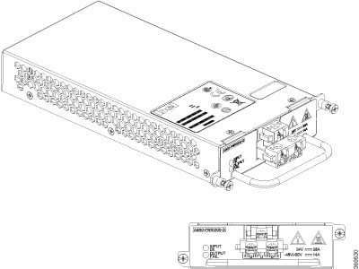
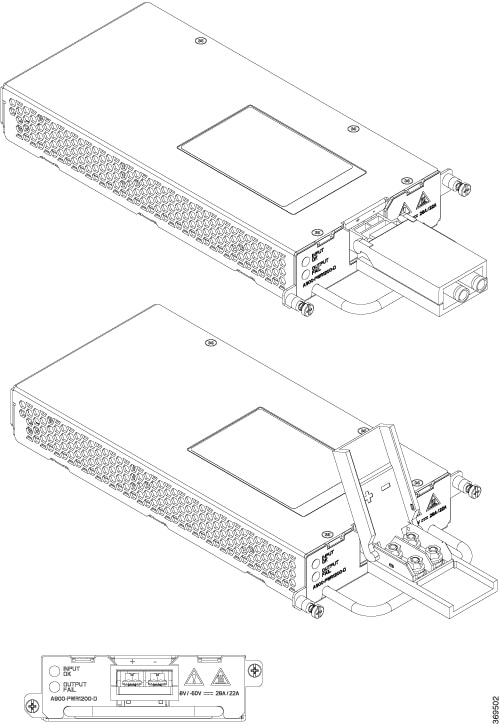
  • Support for 1:1 and 2:1 power supply redundancy configurations, capable of delivering approximately 1.5KW to the router

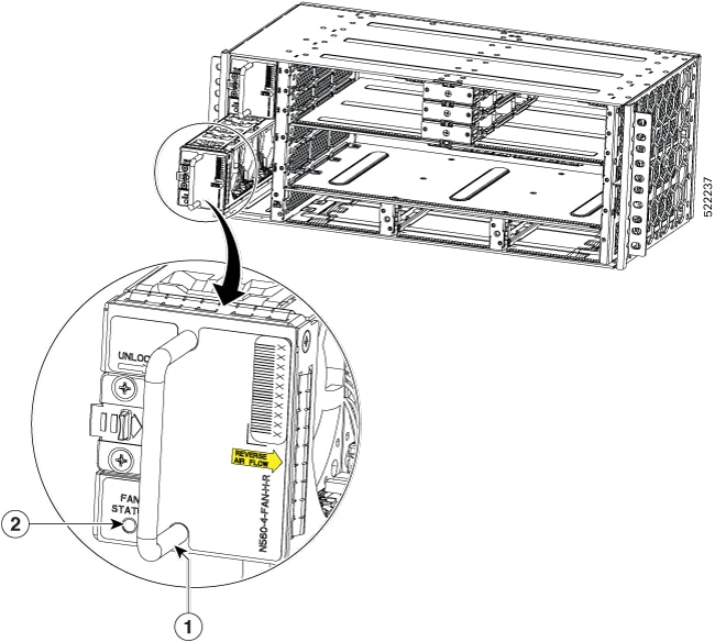
  • Three fan trays working in pull-mode and drawing air from right to left

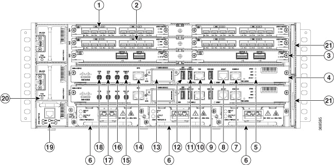
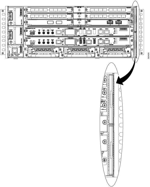
The image below illustrates the Cisco NCS 560-4 Router chassis design.

Figure 1. Cisco NCS 560-4 Router Front Panel
This image displays the front panel design of the NCS 560-4 router. It displays the positions of the slots for route processor, IMs, fans trays, and power supllies.

1

Interface module slot

2

Interface module slot

3

Interface module slot

4

Route Switch Processor (N560-4-RSP4E or N560-4-RSP4)

5

System LEDs

6

Power Supplies (three)

7

RJ-45 Console

8

Management Port

9

USB memory port

10

Time of day timing (ToD) port

11

Auxiliary console

12

USB console

13

GNSS module

14

BITS timing port

15

10 MHz Out

16

10 MHz In

17

1PPS Out

18

1PPS In

19

Primary fan tray

20

Secondary fan tray

21

Fan Filters

The cabling for all interfaces (power, data and control) are on the front side of the chassis. The chassis grounding point is located on the rear side of the chassis.

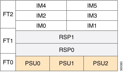
The following image illustrates the slot numbering scheme for the FRUs in Cisco NCS 560-4 router in case of single width IMs.

System Specifications

Table 1. System Specifications - Abridged

Component

Specification

Cisco NCS 560-4 Router - Physical

Height: 7 in. (177.88 mm) - 4RU

Width: 17.44 in. (443 mm)

Depth: 9.5 in. (241.3 mm)

Weight:

  • 55.56 lb (25.2 kg) with two RSPs, three DC power supplies, and loaded with a typical combination of interface module cards

  • 18 lb (8.12 kg) for an empty chassis

Power consumption

Maximum input power 975W (including loss) with 3 power supplies. This is equivalent to 3327 BTU per hr.

AC input voltage and frequency

Voltage range: 85 to 264 VAC, nominal 115 to 230 VAC

Frequency Range: 47 to 63 Hz, nominal 50 to 60 Hz

AC Power Supply MTBF at 40ºC operating temperature

300,000 hours

DC input voltage

For 1200W DC power supply, voltage range: –40.8V to –72V DC, nominal –48V/–60V DC

For the complete set of specifications, see the Cisco Network Convergence System 560-4 Router Data Sheet.

Cisco NCS 560-4 Router Conformal Coating

Table 2. Conformal Coating PIDs

PIDs

Description

NCS560-4-CC

NCS 560 Series Router Chassis 4RU Conformal Coated

N560-4-RSP4E-CC

NCS 560 Series Router 4RU Route Switch Processor 4E, Conformal Coated

N560-4-RSP4-CC 

NCS 560 Series Router 4RU Route Switch Processor 4, Conformal Coated

N560-4-FAN-H-CC

NCS 560 Series Router 4RU High Speed Fan Conformal Coated

N560-4-PWR-FAN-CC 

NCS 560 Series Router 4RU Power Fan Tray Conformal Coated

N560-IMA-2C-CC

NCS 560 2 x 100GE Interface Module, QSFP28 optics, Conformal Coated

A900-IMA8Z-CC

ASR 900 8-port 10GE SFP+ Interface Module, Conformal Coated

A900-IMA8CS1Z-CC

ASR 900 Combo 16 port GE C-SFP + 1 port 10GE SFP+ IM, Conformal Coated

A900-IMA-8Z-L-CC

ASR 900 8 x 10GE Interface Module, Lite,Conformal Coated

Fan Trays

The fan trays are located on the left side of the chassis, while the dust filters are located on the right side of the chassis.

There are three fan tray field replaceable units (FRUs) in the chassis: two secondary fan trays (top two fan trays) and one primary fan tray (at the bottom left of the router).

Figure 2. Fan Trays On the Left Side of Router
Figure 3. N560-4-PWR-FAN-R (Reverse Air Flow Primary Fan Module)

1

Handle

Figure 4. N560-4-FAN-H-R (Reverse Air Flow Secondary Fan Module)

1

Handle

2

LED

Fan redundancy is supported on the following conditions:

  • The router can work indefinitely on a single fan failure. And the time to replace the fan tray may depend upon the temperature levels of the critical components.

  • During two or more fan failures, the router does continue to work as long as all the critical components in the router are within the specified temperature limits.

  • If any fan tray is pulled out of the router during operation, then the remaining fans automatically run at full speed.


Caution


At boot time, the Cisco NCS 560-4 router doesn’t support fan tray redundancy. Ensure all the three fan trays are installed to allow the router to boot up.


The RSP checks for the following conditions before booting up the router:


Note


The onboard FPGA continuously monitors for these conditions and allows the RSP to boot up, only if these conditions are satisfied.


  • All three fan trays are plugged in.

  • Router ambient temperature is less than 73ºC.

  • RSP Outlet temperature is less than 95ºC.

  • ASIC temperature is less than 110ºC.

  • On-board FPGA temperature is less than 105ºC.

Dust Filter (N560-4-FILTER)

The dust filters (set of two filters) are located on the right side of the chassis and prevent dust from entering the chassis.

Figure 5. Dust Filters On the Right Side of the Router

Note


When you use the reverse air flow fan modules, N560-4-PWR-FAN-R, and N560-4-FAN-H-R, use the N560-4-FLTR-BLNK.


Interface Modules

Effective Cisco IOS XR Release 7.9.1, the following interface module is supported:

  • 8-port 10GE / 25GE / 50 Gigabit Ethernet Interface Module (N560-IMA-8Q/4L) is a single-width-single-height IM. The 8 ports of the IM are split into two modes of 4 ports each based on speed.

Effective Cisco IOS XR Release 7.5.2, the following interface module is supported:

  • ASR 900 8 x 10 Gigabit Ethernet Interface Module, Lite, Conformal Coated (A900-IMA-8Z-L-CC): The capabilities of this interface module are same as A900-IMA8Z-L interface module with conformal coating.

Effective Cisco IOS XR Release 7.5.1, 1G mode is supported on A900-IMA8Z-L interface module.

Use the following command to configure A900-IMA8Z-L interface module in 1G mode:

  • hw-module quad 1 slot 0 mode 1g

Effective Cisco IOS XR Release 7.3.1, the following Ethernet interface modules are supported:

  • 2-port 100 Gigabit Ethernet QSFP-28 Module (NCS4200-2H-PQ): The capabilities of this interface module are same as N560-IMA-2C interface module.

  • 8-port 10 Gigabit Ethernet SFP+ Module (NCS4200-8T-PS): The capabilities of this interface module are same as A900-IMA8Z interface module.

  • 8/16-port 1 Gigabit Ethernet and 1-port 10 Gigabit Ethernet Module (NCS4200-1T16G-PS): The capabilities of this interface module are same as A900-IMA8CS1Z-M interface module.

Table 3. Supported Interface Modules and Part Numbers for the Supported Route Processors

RSP Module

Interface Modules

Part Number

Slot

N560-4-RSP4 and N560-4-RSP4E

OR

N560-4-RSP4-CC and N560-4-RSP4E-CC

2-port 100 Gigabit Ethernet Interface Module (2 x 100GE)

N560-IMA-2C

NCS4200-2H-PQ

N560-IMA-2C-DD

N560-IMA-2C-CC

123450,1,2,3

8/16-port 1 Gigabit Ethernet (SFP/SFP) and 1-port 10 Gigabit Ethernet (SFP+) / 2-port 1 Gigabit Ethernet (CSFP) Interface Module

A900-IMA8CS1Z-M

NCS4200-1T16G-PS

A900-IMA8CS1Z-CC

0, 1, 2, 3, 4, 5

8-port 10 Gigabit Ethernet Interface Module (8 x 10GE)

A900-IMA8Z

NCS4200-8T-PS

A900-IMA8Z-CC

A900-IMA8Z-L

A900-IMA-8Z-L-CC

60, 1, 2, 3, 4, 5

1-port 100 Gigabit Ethernet / 200 Gigabit Ethernet CFP2 DCO Module (1 x 100/200GE)

N560-IMA-1W

70, 1, 2, 3

8-port 10 Gigabit Ethernet / 25 Gigabit Ethernet / 50 Gigabit Ethernet Interface Module

(8 x 10/25/50GE)

N560-IMA-8Q/4L

0,18

2,39

4,510

1 Starting with Cisco IOS XR Release 7.2.1, N560- IMA-2C is also supported in slots 2 and 3. In these slots, 100G optics is supported only on port 0. Also, 40G optics are supported in slots 0–3.
2 The maximum bandwidth that can be achieved on slots 0–3 is (6 x 100G and 2 x 40G) or (8 x 40G).
3 Starting with Cisco IOS XR Release 7.3.1, only QSFP-28 100G is supported on the N560-IMA-2C-DD and only on slots 0 and 1 of NCS560-4.
4 Starting with Cisco IOS XR Release 7.4.1, only QSFP-28 100G is supported on the N560-IMA-2C-DD and only on slots 0, 1, 2 and 3 of NCS560-4. In NCS560-4, only one interface, corresponding to port 0 is created when N560-IMA-2C-DD is inserted on slots 2 and 3 and port 1 isn’t effective. Only 100G mode is supported on port 0 of slots 2 and 3.
5 Starting with Cisco IOS XR Release 7.8.1, QSFP-DD 100G ZF1 is supported on the N560-IMA-2C-DD on slots 0, 1, 2 and 3 of NCS560-4. In NCS560-4, on slot 2 and 3 only one interface, corresponding to port 0 is created.
6 Starting with Cisco IOS XR Release 7.5.1, 1G mode is supported on A900-IMA8Z-L. 0, 1, 2, 3, 4, 5 can be in 10G or 1G mode.
7 100G mode is enabled by default. Slots 0 and 1 are supported on 100G and 200G mode. Slots 2 and 3 are supported only on 100G mode.
8 Starting with Cisco IOS XR Release 7.9.1, N560-IMA-8Q/4L is supported on these slots, with a speed combination of 8 x 10G, 4 x 50G, 4 x 10G and 4 x 25G, 4 x 10G and 2 x 50G, or 4 x 25G and 2 x 50G. The default is 8 x 25G.
9 Starting with Cisco IOS XR Release 7.9.1, N560-IMA-8Q/4L is supported on these slots, with a speed combination of 8 x 10G, 2 x 50G and 4 x 10G. The default is 4 x 25G and 4 x 10G.
10 Starting with Cisco IOS XR Release 7.9.1, N560-IMA-8Q/4L is supported on these slots, with a default speed combination of 8x10G.
Table 4. Slot and Port Support for A900-IMA8Z-L for 1G Mode

Slot

Port 0

Port 1

Port 2

Port 3

Port 4

Port 5

Port 6

Port 7

0

10G/1G

10G/1G

10G/1G

10G/1G

10G/1G

10G/1G

10G/1G

10G/1G

1

10G/1G

10G/1G

10G/1G

10G/1G

10G/1G

10G/1G

10G/1G

10G/1G

2

10G/1G

10G/1G

10G/1G

10G/1G

10G/1G

CU SFP

10G/1G

CU SFP

10G/1G

CU SFP

10G/1G

CU SFP

3

10G/1G

10G/1G

10G/1G

10G/1G

10G/1G

CU SFP

10G/1G

CU SFP

10G/1G

CU SFP

10G/1G

CU SFP

4

10G/1G

CU SFP

10G/1G

CU SFP

10G/1G

CU SFP

10G/1G

CU SFP

10G/1G

CU SFP

10G/1G

CU SFP

10G/1G

CU SFP

10G/1G

CU SFP

5

10G/1G

CU SFP

10G/1G

CU SFP

10G/1G

CU SFP

10G/1G

CU SFP

10G/1G

CU SFP

10G/1G

CU SFP

10G/1G

CU SFP

10G/1G

CU SFP

The interface-path-id is rack/ slot/ module/ port. The slash between values is required as part of the notation.

  • For IM N560-IMA-2C, N560-A-2C-CC, NCS4200-2H-PQ, and N560-IMA-2C-DD the port numbering is HundredGigE — 0/0/0/0 - 0/0/0/1

  • For IM A900-IMA8Z, A900-IMA8Z-CC, NCS4200-8T-PS, A900-IMA-8Z-L-CC, and A900-IMA8Z-L the port numbering is TenGigE — 0/0/0/1 - 0/0/0/7

  • For IM A900-IMA8CS1Z-M, A900-IMA8CS1Z-CC, and NCS4200-1T16G-PS, the port numbering is:

    • GigE — 0/0/0/0 - 0/0/0/15

    • TenGigE — 0/0/0/16

  • For IM N560-IMA-1W, HundredGigE (R/S/I/P/i) is created and mapped based on the port-mode configuration of controller optics (R/S/I/P).

    For more information, see the port-mode command in the Interface and Hardware Component Command Reference Guide.

Digital Optical Monitoring

Digital Optical Monitoring (DOM) is supported for the SFP, SFP+, and XFP transceiver modules.

For information on DOM supported transceivers, see Cisco Optics Compatibility Matrix.

For a list of modules, see Cisco NCS 560 Series Routers Interface Modules Data Sheet.

Real time DOM data is collected from SFPs, SFP+, periodically and compared with warning and alarm threshold table values.

The DOM data collected are transceiver transmit bias current, transceiver transmit power, transceiver receive power, and transceiver power supply voltage.

RSP Modules (N560-4-RSP4 and N560-4-RSP4E)

The Cisco NCS 560-4 router supports both, N560-4-RSP4 and N560-4-RSP4E. Each RSP has 32GB CPU memory.

When redundant RSPs are installed, the control and data plane are 1:1 redundant and the standby RSP components are in hot-standby state, ready to take over as active in the event of a failover.


Note


A failover indicates a failure in the software or in the card due to reasons, such as RSP card OIR, host kernel crash or virtual machine crash triggering heartbeat failure.

Whereas, switchover is a graceful operator-initiated task that leads to the RSP being brought down.


The RSP modules handle the data plane, network timing, and control plane functionalities for the router. The RSP configuration allows you to use Cisco IOS XR software to control chassis management, redundancy, external management, and system status indications on the router.

RSP features include:

  • Redundant RSP management—The RSP manages detection of RSPs, exchange of health and status information, role negotiation, function for detection, health and status exchange, role negotiation

  • Traffic management, including buffering, queuing, and scheduling, Ethernet MAC functions

  • Network clocking functions including phase and time-of-day for BITS, 1 PPS, 10 MHz, and 1588 PTP clock references.

  • Storage of software images, system configuration, and SysLog

  • In Service Software Upgrade (ISSU) capability with zero topology loss and minimum packet loss (50 msec)

  • External management interfaces (RS232 console, management ENET, USB console, USB storage) and system status LED indicators

  • Centralized data plane, timing, and control plane functions for the system

  • High-level control of interface modules

  • Management functionalities for the router

  • Control plane (host) CPU and associated memory in which IOS-XR and platform control software runs


Note


If your system includes redundant RSPs, both RSPs should be of the same type and have the same memory size. We strongly recommend that you avoid configuring your router using mixed route processor cards.


GNSS Module (A900-CM-GNSS)

The GNSS module is present on the RSP. It is a pluggable module that allows direct interface with the external antenna.


Note


Using a single GPS antenna input for both RSPs requires usage of external splitters.


Warning


To reduce the risk of fire, use only No. 26 AWG or larger telecommunication line cord. Statement 1023


Note


The GNSS module is not hot swappable.


GNSS Module RF Input Requirements

  • The GNSS module requires an active GPS/GNSS antenna with built-in Low-Noise Amplifier (LNA) for optimal performance. The antenna LNA amplifies the received satellite signals for two purposes:

    • Compensation of losses on the cable

    • Lifting the signal amplitude in the suitable range for the receiver frontend

    The Amplification required is 22dB gain + cable/connector loss + Splitter signal loss.

    The recommended range of LNA gain (LNA gain minus all cable and connector losses) at the connector of the receiver module is 22dB to 30dB with a minimum of 20dB and a maximum of 35dB.

  • GNSS module provides 5V to the active antenna through the same RF input.

  • Surge requirement:

    • GNSS modules have built-in ESD protections on all pins, including the RF-input pin. However, additional surge protection may be required if rooftop antennas are being connected, to meet the regulations and standards for lightning protection in the countries where the end-product is installed.

    • A lightning protection must be mounted at the place where the antenna cable enters the building. The primary lightning protection must be capable of conducting all potentially dangerous electrical energy to PE (Protective Earth).

    • Surge arrestors should support DC-pass and suitable for the GPS frequency range (1.575GHz) with low attenuation.

  • Antenna Sky visibility:


    Note


    The antenna terminal should be earthed at the building entrance in accordance with the ANSI/NFPA 70, the National Electrical Code (NEC), in particular Section 820.93, Grounding of Outer Conductive Shield of a Coaxial Cable.


  • Use a passive splitter if more than one GNSS modules are fed from a single antenna.

Power Supply

The Cisco NCS 560-4 Router supports three 1200W DC and AC power supplies in PSU0, PSU1, and PSU2, in 2+1 mode or 1+1 mode.

The AC and DC power supplies support:

  • -40.8 VDC to -72 VDC

  • 85 VAC to 264 VAC

The power supplies are hot-swappable. They are enclosed to prevent exposure to high voltages, and therefore, no power cable interlock is required. However, the power supplies are automatically shut down when removed from the chassis. The power supplies are rated to deliver 1200W (~100A at +12VDC) to the other FRUs in the system and are rated for operation at 5ºC above the chassis operating temperature.

  • A900-PWR1200-A : EN61000-4-5: Surge AC (2KV CM/2KV DM)

  • A900-PWR1200-D: EN61000-4-5: Surge DC (2KV CM/1KV DM)

  • N560-PWR1200-D-E: EN61000-4-5: Surge DC(2KV CM/DM), ITU K.21 enhanced test level for mains power port (6KV CM/DM) Criteria B


Note


We highly recommend you to use an external surge protector device for the deployments where there is a risk of higher surge than specified for these PSUs.

See the below tables for the AC and DC power supply specifications.

Figure 6. DC Power Supply - A900-PWR1200-D
Figure 7. DC Power Supply - N560-PWR1200-D-E
Table 5. DC Power Supply Specifications

Part numbers

A900-PWR1200-D,

N560-PWR1200-D-E

Input power specification

RTN, -48V

Minimum input voltage

-40.8 VDC

Maximum input voltage

-72 VDC

Output voltage

+12 VDC

Wire gauge for DC input power connections

8 AWG minimum for -48/-60 VDC. Connector accepts 8 AWG maximum.

Maximum power output

1200 W

Figure 8. AC Power Supply - A900-PWR1200-A
Table 6. AC Power Supply Specifications

Part number

A900-PWR1200-A

Input power specification

115VAC/ 230VAC

Input voltage

85/264 VAC

Minimum input voltage

85 VAC

Maximum input voltage

264 VAC

Minimum output voltage

12V

Maximum output voltage

12.4V

Maximum power output

1200 W

Redundancy

The router supports three power supply units that can be used either in 2+1 or 1+ 1 modes, depending on the overall power requirement of the system.

The Cisco NCS 560-4 Router supports current sharing between the power supplies.

If you install a redundant power supply on the Cisco NCS 560-4 Router, we recommend that you connect each power supply to a separate input power source in order to ensure that the router maintains power in the event of a power interruption that is caused by an electrical failure, a wiring fault, or a tripped circuit breaker.

Status LEDs

LEDs are also provided on each power supply to indicate the status of the input power and the health of the power supply.

Network Timing Interfaces

The route processor supports the following network timing interfaces:

  • BITS input/output port—RJ48 jack

  • 1PPS input and output—Mini coaxial connectors

  • 2.048 or 10 MHz input and output—Mini coaxial connectors

  • 1PPS input or output port—Shielded RJ45 jack

Network timing interfaces support redundancy in a redundant RSP configuration. Network timing interfaces on a redundant RSP remain in operation while the RSP is in hot standby mode.

Online Insertion and Removal

The Cisco routers, interface modules, and FAN-H are designed to support online insertion and removal (OIR). However, time-to-OIR for FAN-H fan tray is dependent on the temperature of the chassis. At room temperature of up to 30° C, fan tray OIR should be done within two minutes.


Note


Before replacing the card, you must perform a graceful shutdown of the card to avoid disk corruption.


Table 7. Ambient Teperature and Fan Tray OIR

Ambient Temperature (in Celsius)

Fan Operation

Time

Remarks

30°

All fans are working

2 minutes

Fans working as expected

40°

All fans are working

1 minute 30 seconds

Fans working as expected

40°

Single fan failure

2 minutes

Single fan failure and all other fans running at maximum speed


Note


It is not recommended to perform fan tray OIR above the ambient temperature of 40° C.


The following table describes the parameters for the OIR of the various modules in the router.


Note


Before replacing the card, you must perform a graceful shutdown of the card to avoid disk corruption.
Table 8. Online Insertion and Removal - Parameters

OIR Module

Ambient11

Fan Speed

OIR Time

Comments

Fan Tray12

30°C

100% PWM

5 mins

Single Fan Fail, Other Fans running at 100% PWM

40°C

100% PWM

3 mins

PSU

40°C

As per the fan algorithm

5 mins

Fans running at normal speed

Interface Module13

RSP

11 It is not recommended to perform OIR of any module above 40°C ambient
12 Fan Tray OIR should be performed only when a fan's failed condition is encountered and other fans are spinning at max speed.
13 It is recommended to shut down the interface modules before attempting to remove them from the chassis.

Note


Consecutive IMs insertions, consecutive IMs reload or removal, and subsequent IM re-oinsertion should be done while waiting at least 180s between the actions.