- Preparing for Installation
Installation
This chapter describes how to install your Cisco Industrial Routers (IR500) Series WPAN Gateway and WPAN Range Extender and connect the devices to other devices.
Read these topics, and perform the procedures in this order:
Preparing for Installation
This section provides information about these topics:
- Warnings
- Additional Information for Installation in a Hazardous Environment
- EMC Environmental Conditions for Products Installed in the European Union
Warnings
These warnings are translated into several languages in the Regulatory Compliance and Safety Information for these WPAN gateway and WPAN range extender devices.

Warning![]() IMPORTANT SAFETY INSTRUCTIONS
IMPORTANT SAFETY INSTRUCTIONS
This warning symbol means danger. You are in a situation that could cause bodily injury. Before you work on any equipment, be aware of the hazards involved with electrical circuitry and be familiar with standard practices for preventing accidents. Use the statement number provided at the end of each warning to locate its translation in the translated safety warnings that accompanied this device. Statement 1071
Warning![]() In order to comply with FCC radio frequency (RF) exposure limits, antennas for this product should be located a minimum of 7.9 in. (20 cm) or more from the body of all persons. Statement 332
In order to comply with FCC radio frequency (RF) exposure limits, antennas for this product should be located a minimum of 7.9 in. (20 cm) or more from the body of all persons. Statement 332
Warning![]() Read the installation instructions before connecting the system to the power source. Statement 1004
Read the installation instructions before connecting the system to the power source. Statement 1004
Warning![]() This product relies on the building’s installation for short-circuit (overcurrent) protection. Ensure that the protective device is rated not greater than:
This product relies on the building’s installation for short-circuit (overcurrent) protection. Ensure that the protective device is rated not greater than:
- WPAN Gateway: 2 A
- WPAN Range Extender: 2 A
Statement 1005
Warning![]() This unit is intended for installation in restricted access areas. A restricted access area can be accessed only through the use of a special tool, lock and key, or other means of security. Statement 1017
This unit is intended for installation in restricted access areas. A restricted access area can be accessed only through the use of a special tool, lock and key, or other means of security. Statement 1017
Warning![]() This equipment must be grounded. Never defeat the ground conductor or operate the equipment in the absence of a suitably installed ground conductor. Contact the appropriate electrical inspection authority or an electrician if you are uncertain that suitable grounding is available. Statement 1024
This equipment must be grounded. Never defeat the ground conductor or operate the equipment in the absence of a suitably installed ground conductor. Contact the appropriate electrical inspection authority or an electrician if you are uncertain that suitable grounding is available. Statement 1024
Warning![]() Only trained and qualified personnel should be allowed to install, replace, or service this equipment. Statement 1030
Only trained and qualified personnel should be allowed to install, replace, or service this equipment. Statement 1030
Warning![]() Ultimate disposal of this product should be handled according to all national laws and regulations. Statement 1040
Ultimate disposal of this product should be handled according to all national laws and regulations. Statement 1040
Warning![]() To prevent the system from overheating, do not operate it in an area that exceeds the maximum recommended ambient temperature of:
To prevent the system from overheating, do not operate it in an area that exceeds the maximum recommended ambient temperature of:
- Base WPAN Range Extender: 140°F (60°C)
- Advanced WPAN Range Extender / WPAN Gateway: 158°F (70°C)
Statement 1047
Warning![]() Installation of the equipment must comply with local and national electric codes. Statement 1074
Installation of the equipment must comply with local and national electric codes. Statement 1074
Warning![]() Avoid using or servicing any equipment that has outdoor connections during an electrical storm. There may be a risk of electric shock from lightning. Statement 1088
Avoid using or servicing any equipment that has outdoor connections during an electrical storm. There may be a risk of electric shock from lightning. Statement 1088

- Sides: 1.0 in. (25.4 mm)
- Front: 1.0 in. (25.4 mm)
- Rear: 1.0 in. (25.4 mm)
- Top: 1.0 in. (25.4 mm)—the device can be installed in a 1.25” tall slot, but the mounting surface must have thermal conductive properties equivalent to or better then 302 stainless steel (16.3 W/m-k)
Contact your Cisco Technical Assistance Centre (TAC) if tighter spacings are required.
Additional Information for Installation in a Hazardous Environment
Hazardous Locations Warnings for WPAN Gateway Only
Warning![]() Exposure to some chemicals could degrade the sealing properties of materials used in the sealed relay device. Statement 381
Exposure to some chemicals could degrade the sealing properties of materials used in the sealed relay device. Statement 381
Warning![]() Failure to securely tighten the captive screws can result in an electrical arc if the connector is accidentally removed. Statement 397
Failure to securely tighten the captive screws can result in an electrical arc if the connector is accidentally removed. Statement 397
Warning![]() When you connect or disconnect the power and/or alarm connector with power applied, an electrical arc can occur. This could cause an explosion in hazardous area installations. Be sure that all power is removed from the switch and any other circuits. Be sure that power cannot be accidentally turned on or verify that the area is nonhazardous before proceeding. Statement 1058
When you connect or disconnect the power and/or alarm connector with power applied, an electrical arc can occur. This could cause an explosion in hazardous area installations. Be sure that all power is removed from the switch and any other circuits. Be sure that power cannot be accidentally turned on or verify that the area is nonhazardous before proceeding. Statement 1058
Warning![]() In switch installations in a hazardous location, the DC power source could be located away from the vicinity of the switch. Before performing any of the following procedures, locate the DC circuit to ensure that the power is removed and cannot be turned on accidentally, or verify that the area is nonhazardous before proceeding. Statement 1059
In switch installations in a hazardous location, the DC power source could be located away from the vicinity of the switch. Before performing any of the following procedures, locate the DC circuit to ensure that the power is removed and cannot be turned on accidentally, or verify that the area is nonhazardous before proceeding. Statement 1059
Warning![]() This equipment is supplied as "open type" equipment. It must be mounted within an enclosure that is suitably designed for those specific environmental conditions that will be present and appropriately designed to prevent personal injury resulting from accessibility to live parts. The interior of the enclosure must be accessible only by the use of a tool. The enclosure must meet IP 54 or NEMA type 4 minimum enclosure rating standards. Statement 1063
This equipment is supplied as "open type" equipment. It must be mounted within an enclosure that is suitably designed for those specific environmental conditions that will be present and appropriately designed to prevent personal injury resulting from accessibility to live parts. The interior of the enclosure must be accessible only by the use of a tool. The enclosure must meet IP 54 or NEMA type 4 minimum enclosure rating standards. Statement 1063
Warning![]() Use twisted-pair supply wires suitable for 86°F (30°C) above surrounding ambient temperature outside the enclosure. Statement 1067
Use twisted-pair supply wires suitable for 86°F (30°C) above surrounding ambient temperature outside the enclosure. Statement 1067
Warning![]() This equipment is intended for use in a Pollution Degree 2 industrial environment, in overvoltage Category II applications (as defined in IEC publication 60664-1), and at altitudes up to 2000 meters without derating. Statement 1068
This equipment is intended for use in a Pollution Degree 2 industrial environment, in overvoltage Category II applications (as defined in IEC publication 60664-1), and at altitudes up to 2000 meters without derating. Statement 1068
Warning![]() When used in a Class I, Division 2, hazardous location, this equipment must be mounted in a suitable enclosure with a proper wiring method that complies with the governing electrical codes. Statement 1069
When used in a Class I, Division 2, hazardous location, this equipment must be mounted in a suitable enclosure with a proper wiring method that complies with the governing electrical codes. Statement 1069
Warning![]() Do not connect or disconnect cables to the ports while power is applied to the switch or any device on the network because an electrical arc can occur. This could cause an explosion in hazardous location installations. Be sure that power is removed from the switch and cannot be accidentally be turned on, or verify that the area is nonhazardous before proceeding. Statement 1070
Do not connect or disconnect cables to the ports while power is applied to the switch or any device on the network because an electrical arc can occur. This could cause an explosion in hazardous location installations. Be sure that power is removed from the switch and cannot be accidentally be turned on, or verify that the area is nonhazardous before proceeding. Statement 1070
Warning![]() Explosion Hazard—Do not connect or disconnect wiring while the field-side power is on; an electrical arc can occur. This could cause an explosion in hazardous location installations. Be sure that power is removed or that the area is nonhazardous before proceeding. Statement 1081
Explosion Hazard—Do not connect or disconnect wiring while the field-side power is on; an electrical arc can occur. This could cause an explosion in hazardous location installations. Be sure that power is removed or that the area is nonhazardous before proceeding. Statement 1081
Warning![]() Explosion Hazard—The area must be known to be nonhazardous before installing, servicing, or replacing the unit. Statement 1082
Explosion Hazard—The area must be known to be nonhazardous before installing, servicing, or replacing the unit. Statement 1082
Warning![]() Explosion Hazard—Substitution of components may impair suitability for Class I, Division 2/Zone 2. Statement 1083
Explosion Hazard—Substitution of components may impair suitability for Class I, Division 2/Zone 2. Statement 1083
North American Hazardous Location Approval for WPAN Gateway
EMC Environmental Conditions for Products Installed in the European Union
This section applies to products to be installed in the European Union.
The equipment is intended to operate under the following environmental conditions with respect to EMC:
- A separate defined location under the user's control.
- Earthing and bonding shall meet the requirements of ETS 300 253 or CCITT K27.
- AC-power distribution shall be one of the following types, where applicable: TN-S and TN-C as defined in IEC 364-3.
In addition, if equipment is operated in a domestic environment, interference could occur.
Tools and Hardware Required
WPAN Gateway Tools and Hardware Required
The tools and hardware required for installing the WPAN gateway are:
- For power and alarm connections, use UL- and CSA-rated style 1007 or 1569 twisted-pair copper appliance wiring material (AWM) wire
- Wire-stripping tools for stripping 10- and 18-gauge wires
- Ratcheting torque flathead screwdriver that exerts up to 15 in-lb (1.69 N-m) of pressure.
- A number-2 Phillips screwdriver.
WPAN Range Extender Tools and Hardware Required
The tools and hardware required for installing the WPAN range extender are:
Unpacking the Components
- WPAN Gateway Package Contents
- Unpacking the WPAN Gateway
- WPAN Range Extender Package Contents
- Unpacking the WPAN Range Extender
WPAN Gateway Package Contents
The typical WPAN gateway package contains the following items:
Unpacking the WPAN Gateway
When you are unpacking the WPAN gateway, do not remove the foam blocks attached to the antenna connectors. The foam protects the antenna connectors during installation.
To unpack the WPAN gateway, follow these steps:
Step 1![]() Open the shipping container and carefully remove the contents.
Open the shipping container and carefully remove the contents.
Step 2![]() Return all packing materials to the shipping container, and save it.
Return all packing materials to the shipping container, and save it.
Step 3![]() Ensure that all items listed in “Package Contents” section are included in the shipment. If any item is damaged or missing, notify your sales representative.
Ensure that all items listed in “Package Contents” section are included in the shipment. If any item is damaged or missing, notify your sales representative.
WPAN Range Extender Package Contents
The typical WPAN range extender package contains the following items:
Unpacking the WPAN Range Extender
When you are unpacking the WPAN gateway, do not remove the foam blocks attached to the antenna connectors. The foam protects the antenna connectors during installation.
To unpack the range extender, follow these steps:
Step 1![]() Open the shipping container and carefully remove the contents.
Open the shipping container and carefully remove the contents.
Step 2![]() Return all packing materials to the shipping container, and save it.
Return all packing materials to the shipping container, and save it.
Step 3![]() Ensure that all items listed in “Package Contents” section are included in the shipment. If any item is damaged or missing, notify your sales representative.
Ensure that all items listed in “Package Contents” section are included in the shipment. If any item is damaged or missing, notify your sales representative.
Installation Guidelines
Because the WPAN gateway and WPAN range extender are radio devices, they are susceptible to common causes of interference that can reduce throughput and range. Follow these basic guidelines to ensure the best possible performance:
- For information on planning and initially configuring your Cisco Mesh network, refer to the Cisco Wireless Mesh Access Points, Design and Deployment Guide on Cisco.com
- Review the FCC guidelines for installing and operating outdoor wireless LAN devices at: http://www.cisco.com/en/US/partner/prod/collateral/routers/ps272/data_sheet_c78-647116_ps11451_Products_Data_Sheet.html
- Perform a site survey before beginning the installation.
- Install the WPAN gateway and WPAN range extender in an area where structures, trees, or hills do not obstruct radio signals to and from the devices.
- The WPAN gateway and WPAN range extender can be installed at any height, but best throughput is achieved when all the WPAN gateways and WPAN range extenders are mounted at the same height. We recommend installing the devices no higher than 40 feet to allow support for wireless clients on the ground.
- Sides: 1.0 in. (25.4 mm)
- Front: 1.0 in. (25.4 mm)
- Rear: 1.0 in. (25.4 mm)
- Top: 1.0 in. (25.4 mm)—the device can be installed in a 1.25” tall slot, but the mounting surface must have thermal conductive properties equivalent to or better then 302 stainless steel (16.3 W/m-k)
Contact your Cisco Technical Assistance Centre (TAC) if tighter spacings are required.
Site Surveys
Every network application is a unique installation. Before installing multiple WPAN gateways and WPAN range extenders, you should perform a site survey to determine the optimum use of networking components and to maximize range, coverage, and network performance.
Consider the following operating and environmental conditions when performing a site survey:
- Data rates—Sensitivity and range are inversely proportional to data bit rates. The maximum radio range is achieved at the lowest workable data rate. A decrease in receiver sensitivity occurs as the radio data increases.
- Antenna type and placement—Proper antenna configuration is a critical factor in maximizing radio range. As a general rule, range increases in proportion to antenna height. However, do not place the antenna higher than necessary, because the extra height also increases potential interference from other unlicensed radio systems and decreases the wireless coverage from the ground.
- Physical environment—Clear or open areas provide better radio range than closed or filled areas.
- Obstructions—Physical obstructions such as buildings, trees, or hills can hinder performance of wireless devices. Avoid locating the devices in a location where there is an obstruction between the sending and receiving antennas.
Becoming Familiar with WPAN Gateway and WPAN Range Extender Installation Options and Components
WPAN Gateway Installation Options and Components
The WPAN gateway has a ruggedized IP41 enclosure and it can be installed in the following locations:
- Outdoor cabinet installations—the WPAN gateway is mounted on a DIN rail within the cabinet. For more information, see the “Mounting the WPAN Gateway on a DIN Rail” section.
- Interior wall installations—the WPAN gateway is mounted on a wall using wall mounting brackets. For more information, see the “Mounting the WPAN Gateway on a Wall” section.
WPAN Range Extender Installation Options and Components
The WPAN range extender (base or advanced model) is mounted on a pole. For more information, see the “Mounting the Range Extender on a Pole” section.
Installing the Devices
Mounting the WPAN Gateway
Mounting the WPAN Gateway on a DIN Rail
Attaching the DIN Rail Mounting Bracket to the WPAN Gateway
The WPAN gateway is attached to a DIN rail spring loaded mounting bracket (part number 700-103853-01) for mounting on a DIN rail.
To attach the DIN rail mounting bracket to the gateway:
Step 1![]() Decide if the WPAN gateway is to be mounted in a horizontal or vertical orientation.
Decide if the WPAN gateway is to be mounted in a horizontal or vertical orientation.
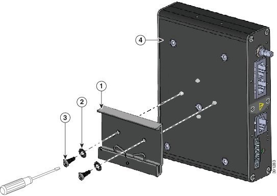
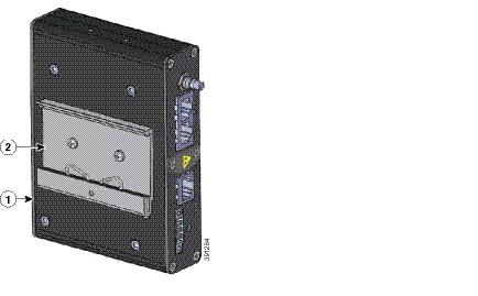
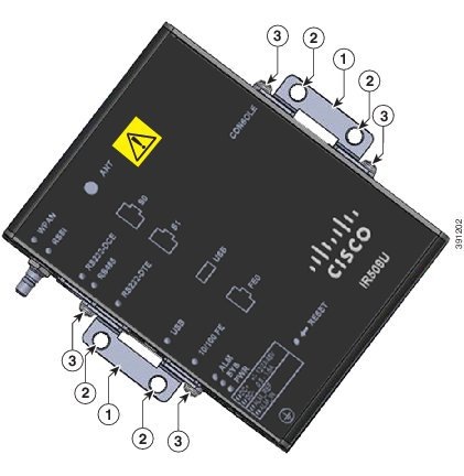
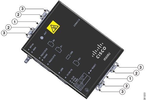
Step 2![]() Align the DIN rail mounting bracket with the mounting hoes as shown in Figure 2-1, and screw the mounting screws and washers into place. The completed assembly is shown in Figure 2-2.
Align the DIN rail mounting bracket with the mounting hoes as shown in Figure 2-1, and screw the mounting screws and washers into place. The completed assembly is shown in Figure 2-2.
Figure 2-1 Attaching the DIN Rail Mounting Bracket to the WPAN Gateway
|
|
|
||
|
|
|
Figure 2-2 Assembled WPAN Gateway and DIN Rail Mounting Bracket
|
|
|
|
|
Attaching the WPAN Gateway to a DIN Rail
To attach the WPAN Gateway to a DIN Rail:
Step 1![]() Position the base of the WPAN Gateway (and the attached DIN mounting rail) directly in front of the DIN rail.
Position the base of the WPAN Gateway (and the attached DIN mounting rail) directly in front of the DIN rail.
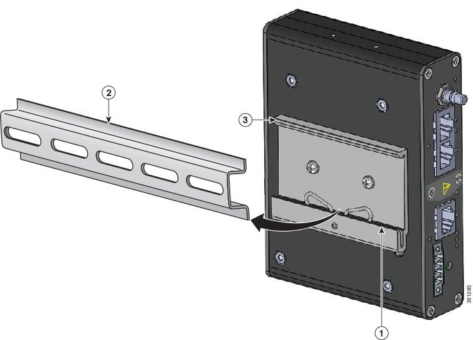
Step 2![]() Place the spring loaded lower lip of the DIN mounting bracket over the lower edge of the DIN rail as shown in Figure 2-3, and put pressure on it by pressing it upwards. Maintain the pressure.
Place the spring loaded lower lip of the DIN mounting bracket over the lower edge of the DIN rail as shown in Figure 2-3, and put pressure on it by pressing it upwards. Maintain the pressure.
Figure 2-3 Positioning the WPAN Gateway on the DIN Rail
|
|
|
||
|
|
|
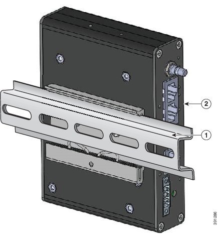
Step 3![]() Place the upper lip of the DIN mounting bracket over the upper edge of the DIN rail. Release the pressure on the lower lip. The WPAN Gateway will mount onto the DIN rail as shown in Figure 2-4.
Place the upper lip of the DIN mounting bracket over the upper edge of the DIN rail. Release the pressure on the lower lip. The WPAN Gateway will mount onto the DIN rail as shown in Figure 2-4.
Figure 2-4 WPAN Gateway Mounted on the DIN Rail
|
|
|
|
|
Mounting the WPAN Gateway on a Wall
To mount the WPAN gateway on a wall:
Step 1![]() Note the mounting orientation of the WPAN gateway based on the use of front and rear wall mounting brackets (see Figure 2-5) or side wall mounting brackets (see Figure 2-6).
Note the mounting orientation of the WPAN gateway based on the use of front and rear wall mounting brackets (see Figure 2-5) or side wall mounting brackets (see Figure 2-6).
Figure 2-5 WPAN Gateway with Front and Rear Wall Mounting Brackets
|
|
|
||
|
|
|
Figure 2-6 WPAN Gateway with Side Wall Mounting Brackets
|
|
|
||
|
|
|
Step 2![]() Prepare M8 threaded mounting holes on the wall or the associated mounting plate based on the mounting dimensions.
Prepare M8 threaded mounting holes on the wall or the associated mounting plate based on the mounting dimensions.
Step 3![]() Place the extender and brackets in the mounting position and screw the M8 mounting screws into position.
Place the extender and brackets in the mounting position and screw the M8 mounting screws into position.
Mounting the Range Extender
Mounting the Range Extender on a Pole
This section includes all the procedures required to mount the range extender on any supported pole type. This section covers:
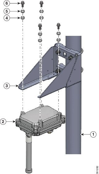
Extender Orientation
When mounting the WPAN extender on a pole, ensure that the extender is oriented with the antenna pointing downwards (see Figure 2-8).
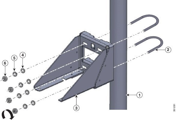
Attaching the Mounting Bracket to a Pole
Attach the mounting bracket to the pole as shown in Fig.
Figure 2-7 Attaching the Range Extender Mounting Bracket to a Pole
|
|
|
||
|
|
|
||
|
|
|
Attaching the Range Extender to the Mounting Bracket
Attach the range extender to the mounting bracket as shown in Figure 2-8.
Figure 2-8 Attaching the Range Extender to the Pole Mounting Bracket
|
|
|
||
|
|
|
||
|
|
|
Connecting the Protective Ground and Power
- Grounding the WPAN Gateway
- Wiring the WPAN Gateway DC Power
- Grounding the WPAN Range Extender
- Wiring the WPAN Range Extender AC Power
Grounding the WPAN Gateway
Make sure to follow any grounding requirements at your site.
Warning![]() This equipment must be grounded. Never defeat the ground conductor or operate the equipment in the absence of a suitably installed ground conductor. Contact the appropriate electrical inspection authority or an electrician if you are uncertain that suitable grounding is available. Statement 1024
This equipment must be grounded. Never defeat the ground conductor or operate the equipment in the absence of a suitably installed ground conductor. Contact the appropriate electrical inspection authority or an electrician if you are uncertain that suitable grounding is available. Statement 1024
Warning![]() This equipment is intended to be grounded to comply with emission and immunity requirements. Ensure that the switch functional ground lug is connected to earth ground during normal use. Statement 1064
This equipment is intended to be grounded to comply with emission and immunity requirements. Ensure that the switch functional ground lug is connected to earth ground during normal use. Statement 1064
The ground lug (part number 32-204389=) for the WPAN gateway is supplied.
To ground the WPAN Gateway to earth ground by using the ground screw, follow these steps:
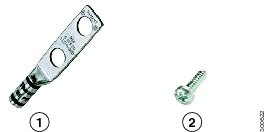
Step 1![]() Locate the ground screw (part number 48-1163-01=) in the WPAN gateway packaging kit. Store the ground screw for later use.
Locate the ground screw (part number 48-1163-01=) in the WPAN gateway packaging kit. Store the ground screw for later use.
Step 2![]() Use a wire stripping tool to strip the 14-to-16 AWG grounding wire to 0.22 in. (5.56 mm).
Use a wire stripping tool to strip the 14-to-16 AWG grounding wire to 0.22 in. (5.56 mm).
Step 3![]() Insert the ground wire into the ring terminal lug, and using a crimping tool, crimp the terminal to the wire. See Figure 2-9.
Insert the ground wire into the ring terminal lug, and using a crimping tool, crimp the terminal to the wire. See Figure 2-9.
Figure 2-9 Crimping the Ring Terminal
Step 4![]() Slide the ground screw through the terminal.
Slide the ground screw through the terminal.
Step 5![]() Insert the ground screw into the functional ground screw opening on the right side panel.
Insert the ground screw into the functional ground screw opening on the right side panel.
Step 6![]() Use a ratcheting torque screwdriver to tighten the ground screw and ring terminal to the WPAN gateway side panel to 3.5 in-lb (0.4 N-m). The torque should not exceed 3.5 in-lb (0.4 N-m). See Figure 2-10.
Use a ratcheting torque screwdriver to tighten the ground screw and ring terminal to the WPAN gateway side panel to 3.5 in-lb (0.4 N-m). The torque should not exceed 3.5 in-lb (0.4 N-m). See Figure 2-10.
Figure 2-10 Installing the Ground-Lug Screw
|
|
Step 7![]() Attach the other end of the ground wire to a grounded bare metal surface, such as a ground bus, a grounded DIN rail, or a grounded bare rack.
Attach the other end of the ground wire to a grounded bare metal surface, such as a ground bus, a grounded DIN rail, or a grounded bare rack.
Wiring the WPAN Gateway DC Power
Warning![]() When you connect or disconnect the power and/or alarm connector with power applied, an electrical arc can occur. This could cause an explosion in hazardous area installations. Be sure that all power is removed from the switch and any other circuits. Be sure that power cannot be accidentally turned on or verify that the area is nonhazardous before proceeding. Statement 1058
When you connect or disconnect the power and/or alarm connector with power applied, an electrical arc can occur. This could cause an explosion in hazardous area installations. Be sure that all power is removed from the switch and any other circuits. Be sure that power cannot be accidentally turned on or verify that the area is nonhazardous before proceeding. Statement 1058
Warning![]() Explosion Hazard—The area must be known to be nonhazardous before installing, servicing, or replacing the unit. Statement 1082
Explosion Hazard—The area must be known to be nonhazardous before installing, servicing, or replacing the unit. Statement 1082
Warning![]() Explosion Hazard—Substitution of components may impair suitability for Class I, Division 2/Zone 2. Statement 1083
Explosion Hazard—Substitution of components may impair suitability for Class I, Division 2/Zone 2. Statement 1083
To wire the WPAN Gateway to a DC power source:
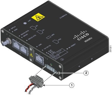
Step 1![]() Locate the power and alarm connector on the WPAN gateway front panel (see Figure 2-11).
Locate the power and alarm connector on the WPAN gateway front panel (see Figure 2-11).
Figure 2-11 WPAN Gateway Power and Alarm Connector
Step 2![]() Identify the connector positive and return DC power connections. The labels for the power and alarm connector are shown in Table 2-1 .
Identify the connector positive and return DC power connections. The labels for the power and alarm connector are shown in Table 2-1 .
Step 3![]() Measure two strands of twisted-pair copper wire (18-to-20 AWG) long enough to connect to the DC power source.
Measure two strands of twisted-pair copper wire (18-to-20 AWG) long enough to connect to the DC power source.
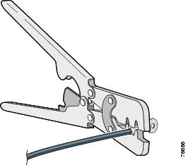
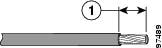
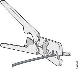
Step 4![]() Using an 18-gauge wire-stripping tool, strip each of the two twisted pair wires coming from each DC-input power source to 0.25 inch (6.3 mm) ± 0.02 inch (0.5 mm). Do not strip more than 0.27 inch (6.8 mm) of insulation from the wire. Stripping more than the recommended amount of wire can leave exposed wire from the power connector after installation.
Using an 18-gauge wire-stripping tool, strip each of the two twisted pair wires coming from each DC-input power source to 0.25 inch (6.3 mm) ± 0.02 inch (0.5 mm). Do not strip more than 0.27 inch (6.8 mm) of insulation from the wire. Stripping more than the recommended amount of wire can leave exposed wire from the power connector after installation.
Figure 2-12 Stripping the Power Connection Wire
|
|
Step 5![]() Remove the two captive screws that attach the power and alarm connector to the WPAN gateway, and remove the connector. See Figure 2-13.
Remove the two captive screws that attach the power and alarm connector to the WPAN gateway, and remove the connector. See Figure 2-13.
Figure 2-13 Removing the Power and Alarm Connector from the WPAN Gateway
|
|
|
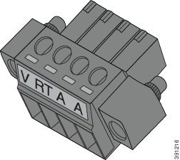
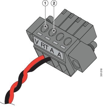
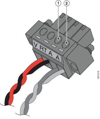
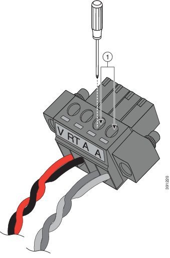
Step 6![]() On the power and alarm connector, insert the exposed part of the positive wire into the connection labeled "V" and the exposed part of the return wire into the connection labeled "RT". See Figure 2-14. Make sure that you cannot see any wire lead. Only wire with insulation should extend from the connector.
On the power and alarm connector, insert the exposed part of the positive wire into the connection labeled "V" and the exposed part of the return wire into the connection labeled "RT". See Figure 2-14. Make sure that you cannot see any wire lead. Only wire with insulation should extend from the connector.
Figure 2-14 Inserting the Power and Return Connections in the Power and Alarm Connector
|
|
|
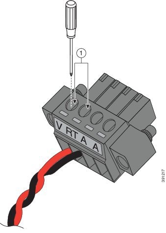
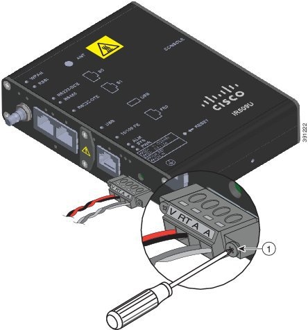
Step 7![]() Use a ratcheting torque flathead screwdriver to torque the power connector captive screws (above the installed wire leads) to 2 in-lb (0.23 N-m). See Figure 2-15.
Use a ratcheting torque flathead screwdriver to torque the power connector captive screws (above the installed wire leads) to 2 in-lb (0.23 N-m). See Figure 2-15.
Figure 2-15 Torquing the Power and Ground Captive Screws
|
|
Step 8![]() Connect the other end of the positive wire to the positive terminal on the DC power source, and connect the other end of the return wire to the return terminal on the DC power source.
Connect the other end of the positive wire to the positive terminal on the DC power source, and connect the other end of the return wire to the return terminal on the DC power source.
The power and alarm connector is attached to the WPAN gateway when the alarm connections on the connector are completed. For information about wiring the alarm connections and attaching the power and alarm connector, see the “Attaching the Power and Alarm Connector to the WPAN Gateway” section.
Grounding the WPAN Range Extender
In all installations, after the WPAN range extender is mounted, you must properly ground the unit before connecting power cables.
Warning![]() This equipment must be grounded. Never defeat the ground conductor or operate the equipment in the absence of a suitably installed ground conductor. Contact the appropriate electrical inspection authority or an electrician if you are uncertain that suitable grounding is available. Statement 1024
This equipment must be grounded. Never defeat the ground conductor or operate the equipment in the absence of a suitably installed ground conductor. Contact the appropriate electrical inspection authority or an electrician if you are uncertain that suitable grounding is available. Statement 1024
Warning![]() Installation of the equipment must comply with local and national electrical codes. Statement 1074
Installation of the equipment must comply with local and national electrical codes. Statement 1074
The range extender is shipped with a grounding kit as shown in Figure 2-16.
Figure 2-16 WPAN Range Extender Grounding Kit Contents
|
|
|
|
|

Note![]() You can perform these steps when the mounting bracket security panel is installed.
You can perform these steps when the mounting bracket security panel is installed.
To ground the range extender, follow these steps:
Step 1![]() Use a crimping tool to crimp the 6-gauge ground wire (included in the grounding kit) to the grounding lug. See Figure 2-17.
Use a crimping tool to crimp the 6-gauge ground wire (included in the grounding kit) to the grounding lug. See Figure 2-17.
Figure 2-17 Crimping the Ground Lug
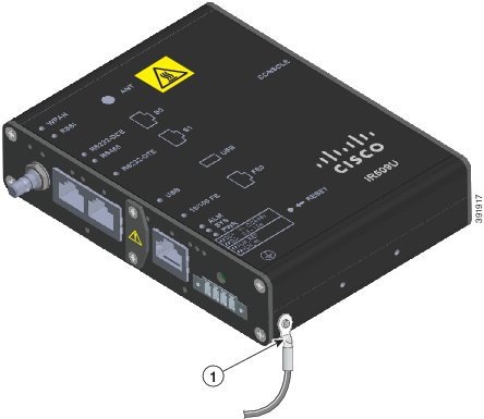
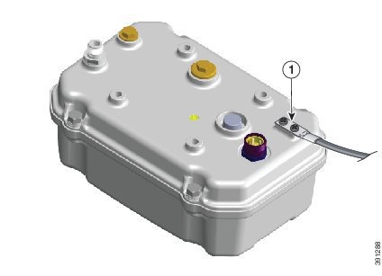
Step 2![]() Connect the grounding lug to the range extender ground connection point shown in Figure 2-18 using the supplied screws. Tighten the screws to 10 to 12 foot-pounds of torque.
Connect the grounding lug to the range extender ground connection point shown in Figure 2-18 using the supplied screws. Tighten the screws to 10 to 12 foot-pounds of torque.
Figure 2-18 Installing the Ground Lug
|
|
Step 3![]() If necessary, strip the other end of the ground wire and connect it to a reliable earth ground, such as a grounding rod or an appropriate grounding point on a pole that is grounded.
If necessary, strip the other end of the ground wire and connect it to a reliable earth ground, such as a grounding rod or an appropriate grounding point on a pole that is grounded.
Wiring the WPAN Range Extender AC Power
When wiring the range extender AC power, you must ensure that the following conditions are met:
- AC power can be readily and conveniently removed from the WPAN range extender. The power should not be removed by disconnecting the AC power connector on the unit. It should be removed by disabling AC power at the power circuit.
Warning![]() The AC power supply has double pole/neutral fusing. Statement 188
The AC power supply has double pole/neutral fusing. Statement 188
Warning![]() The plug-socket combination must be accessible at all times, because it serves as the main disconnecting device. Statement 1019
The plug-socket combination must be accessible at all times, because it serves as the main disconnecting device. Statement 1019
- You must protect AC power plugs and AC receptacles from water and other outdoor elements. You can use a UL-listed waterproofing enclosure suitable for covering the AC receptacle and AC power plug that supplies power to the unit, as described in Article 406 of the National Electric Code (NEC).
- When you install the unit outdoors, or in a wet or damp location, the AC branch circuit that powers the unit should have ground fault protection (GFCI), as required by Article 210 of the NEC.
- If the power cord goes through a metal cover, a bushing should be installed to prevent fraying of the cord. When using a strain relief bushing, you should follow these recommendations:
–![]() Use bushings that are safety certified
Use bushings that are safety certified
AC Power Cable
The WPAN range extender supports the Cisco AC power cable that is shipped with the unit. One end of the cable has the range extender AC power connector; the other end is unfinished and you must provide and attach an AC power plug, or terminate the cable at your installation site. The AC power plug or termination method you use depends on the power source, such as a junction box, at your site.
If you attach an AC power plug:
- Use a plug that complies with local and national electrical codes.
- Verify the connection between the cable and plug is weatherproof.
You might have to cut the cable if a specific cable length is needed for your installation.
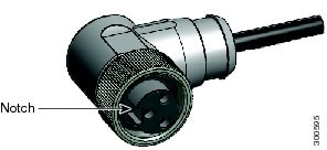
Figure 2-19 WPAN Gateway AC Power Cable (WPAN Gateway Connector End)
Connecting to AC Power
To connect the WPAN range extender power connector in Figure 2-19 to an AC power source, follow these steps:
Step 1![]() Verify that the unit is grounded as described in the “Grounding the WPAN Range Extender” section.
Verify that the unit is grounded as described in the “Grounding the WPAN Range Extender” section.
Step 2![]() Turn off power to the AC power source at the designated circuits.
Turn off power to the AC power source at the designated circuits.
Step 3![]() Align the notch in the WPAN range extender power cable connector with the key in the range extender AC power connector, and push the cable connector into the range extender connector. When the cable connector is fully seated, rotate the cable connector ring clockwise until it is hand-tightened to a torque of 6-7 ft-lbs (8.13-9.49 N-m).
Align the notch in the WPAN range extender power cable connector with the key in the range extender AC power connector, and push the cable connector into the range extender connector. When the cable connector is fully seated, rotate the cable connector ring clockwise until it is hand-tightened to a torque of 6-7 ft-lbs (8.13-9.49 N-m).
Step 4![]() Confirm the WPAN antennas are connected to the range extender before you apply power to the range extender.
Confirm the WPAN antennas are connected to the range extender before you apply power to the range extender.
Step 5![]() Connect the other end of the AC power cable to the power source, using the instructions that came with the connecting device.
Connect the other end of the AC power cable to the power source, using the instructions that came with the connecting device.
Step 6![]() Turn on AC power at the designated circuits. The range extender will power on and boot the software image.
Turn on AC power at the designated circuits. The range extender will power on and boot the software image.
Wiring the Alarm Circuits
Wiring the WPAN Gateway Alarm
To connect the WPAN gateway alarm connections:
Step 1![]() Note the alarm connections as described in Figure 2-20. The alarm connection labels are described in Table 2-2 .
Note the alarm connections as described in Figure 2-20. The alarm connection labels are described in Table 2-2 .
Figure 2-20 WPAN Gateway Power and Alarm Connector
Step 2![]() Measure two strands of twisted-pair wire (18-to-20 AWG) long enough to connect to the external alarm device.
Measure two strands of twisted-pair wire (18-to-20 AWG) long enough to connect to the external alarm device.
Step 3![]() Use a wire stripper to remove the casing from both ends of each wire to 0.25 inch (6.3 mm) ± 0.02 inch (0.5 mm). Do not strip more than 0.27 inch (6.8 mm) of insulation from the wires. Stripping more than the recommended amount of wire can leave exposed wire from the alarm connector after installation.
Use a wire stripper to remove the casing from both ends of each wire to 0.25 inch (6.3 mm) ± 0.02 inch (0.5 mm). Do not strip more than 0.27 inch (6.8 mm) of insulation from the wires. Stripping more than the recommended amount of wire can leave exposed wire from the alarm connector after installation.
Step 4![]() Insert the exposed wires for the external alarm device into the power and alarm connector connections as shown in Figure 2-21.
Insert the exposed wires for the external alarm device into the power and alarm connector connections as shown in Figure 2-21.
Figure 2-21 Inserting Wires into the Alarm Connections
|
|
|
Step 5![]() Use a ratcheting torque flathead screwdriver to tighten the alarm connector captive screw (above the installed wire leads) to 2 in-lb (0.23 N-m). See Figure 2-22.
Use a ratcheting torque flathead screwdriver to tighten the alarm connector captive screw (above the installed wire leads) to 2 in-lb (0.23 N-m). See Figure 2-22.
Figure 2-22 Securing the Alarm Connections Captive Screws
|
|
Attaching the Power and Alarm Connector to the WPAN Gateway
Warning![]() This product relies on the building’s installation for short-circuit (overcurrent) protection. Ensure that the protective device is rated not greater than:
This product relies on the building’s installation for short-circuit (overcurrent) protection. Ensure that the protective device is rated not greater than:
- WPAN Gateway: 2 A
- WPAN Range Extender: 2 A
Statement 1005
To attach the power and alarm connector to the front panel of WPAN gateway:
Step 1![]() Insert the power and alarm connector into the receptacle on the WPAN gateway front panel. See Figure 2-23.
Insert the power and alarm connector into the receptacle on the WPAN gateway front panel. See Figure 2-23.
Figure 2-23 Connecting the Power and Alarm Connector to the WPAN Gateway
|
|
Step 2![]() Use a ratcheting torque flathead screwdriver to tighten the captive screws on both sides of the power and alarm connector to 2 in-lb (0.23 N-m).
Use a ratcheting torque flathead screwdriver to tighten the captive screws on both sides of the power and alarm connector to 2 in-lb (0.23 N-m).
Connecting to Device Ports
Connecting to WPAN Gateway Ports
Connecting to the RS232DCE/RS485 or RS232-DTE Ports
To connect to the RS232DCE/RS485 or RS232-DTE Ports:
Step 1![]() Use a twisted four-pair, Category 5 or higher cable for connecting to the port.
Use a twisted four-pair, Category 5 or higher cable for connecting to the port.
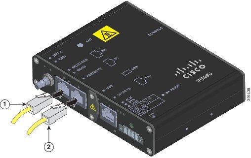
Step 2![]() Connect the cable to the RJ-45 connector port. See Figure 2-24.
Connect the cable to the RJ-45 connector port. See Figure 2-24.
Figure 2-24 Connecting to the RS232DCE/RS485 or RS232-DTE Ports
|
|
|
|
|
Step 3![]() Connect the other end of the cable to the connecting device.
Connect the other end of the cable to the connecting device.
Connecting to the 10/100 Fast Ethernet Port
To connect to the 10/100 Fast Ethernet port:
Step 1![]() Use a twisted four-pair, Category 5 or higher cable for connecting to the port.
Use a twisted four-pair, Category 5 or higher cable for connecting to the port.
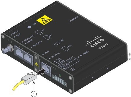
Step 2![]() Connect the cable to the RJ-45 connector port. See Figure 2-25.
Connect the cable to the RJ-45 connector port. See Figure 2-25.
Figure 2-25 Connecting to the 10/100 Fast Ethernet Port
|
|
Step 3![]() Connect the other end of the cable to the connecting device. The 10/100 FE LED turns on when both the WPAN gateway and the connected device have established a link.
Connect the other end of the cable to the connecting device. The 10/100 FE LED turns on when both the WPAN gateway and the connected device have established a link.
Connecting to the USB Port
Note![]() If you are connecting to the USB port:
If you are connecting to the USB port:
- a connection (to the USB port) can only be made in a non-hazardous environment
- the USB port cover must be reinstalled before the WPAN gateway can be deployed in a hazardous environment
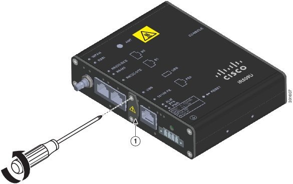
Step 1![]() Remove the two captive screws that attach the USB port cover to the front panel. See Figure 2-26.
Remove the two captive screws that attach the USB port cover to the front panel. See Figure 2-26.
Figure 2-26 Removing the USB Port Cover Captive Screws
|
|
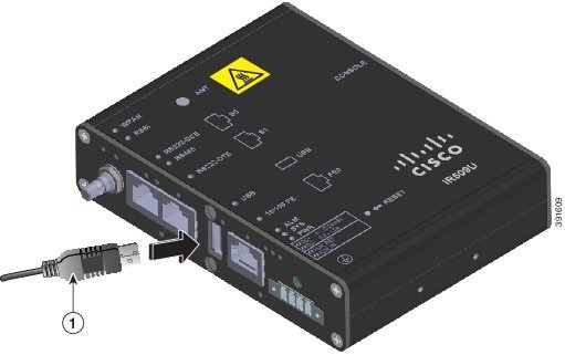
Step 2![]() Connect the USB cable connector to the USB port. See Figure 2-27.
Connect the USB cable connector to the USB port. See Figure 2-27.
Figure 2-27 Connecting the USB Cable Connector to the USB Port
|
|
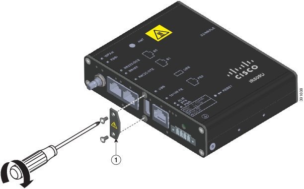
Step 3![]() When you are finished using the USB port, put the USB port cover back in place. See Figure 2-28.
When you are finished using the USB port, put the USB port cover back in place. See Figure 2-28.
Figure 2-28 Placing the USB Port Cover Back in Place
Connecting to the Console Port
For information about connecting to the WPAN gateway console port, see the “Connecting to the WPAN Gateway Console Port” section.
Connecting to WPAN Range Extender Ports
Connecting to the Console Port
For information about connecting to the WPAN range extender console port, see the “Connecting to the WPAN Range Extender Console Port” section.
 Feedback