Cable and Connectors
This appendix describes the cables and connectors used with the Cisco Industrial Routers (IR500) Series WPAN Gateway and WPAN Range Extender devices. The sections include:
Connector Specifications
- WPAN Gateway Power and Alarm Connector
- WPAN Gateway Console Port
- WPAN Gateway RS232/RS485 DCE Serial Port
- WPAN Gateway RS232 DTE Serial Port
- WPAN Gateway USB Port
- WPAN Gateway 10/100 Fast Ethernet Port
- WPAN Range Extender Power Connector
- WPAN Range Extender Console Port
WPAN Gateway Power and Alarm Connector
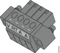
Figure B-1 shows the WPAN gateway power and alarm connector. The connector is a 4 way screw terminal header. Table B-1 describes the connector pinouts.
Figure B-1 WPAN Gateway Power and Alarm Connector
|
|
|
|
|---|---|---|
WPAN Gateway Console Port
The console port on the WPAN gateway uses an RJ-45 connector. The console port is an RS232 serial port. Table B-7 describes the pinouts.
|
|
|
|---|---|
WPAN Gateway RS232/RS485 DCE Serial Port
The WPAN Gateway RS232/RS485 serial port uses an RJ-45 connector. Table B-3 shows the pinouts, depending on whether the user selects RS232 or RS485.
|
|
|
|
|
|---|---|---|---|
WPAN Gateway RS232 DTE Serial Port
The WPAN gateway RS232 DTE serial port uses and RJ-45 connector. Table B-4 describes the pinouts.
|
|
|
|---|---|
WPAN Gateway USB Port
The WPAN gateway USB port uses a Standard A connector. Table B-5 describes the pinouts.
|
|
|
|
|---|---|---|
WPAN Gateway 10/100 Fast Ethernet Port
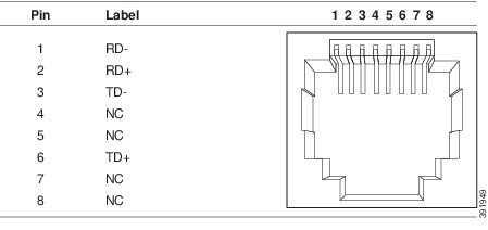
The 10/100 Fast Ethernet port uses an RJ-45 connector. Figure B-2 shows the pinouts. This port supports Auto-MDIX (Automatic TX/RX crossover) and Auto-Polarity (Auto +/- polarity detection and correction).
Figure B-2 WPAN Gateway 10/100 Fast Ethernet Port Pinouts
WPAN Range Extender Power Connector
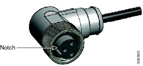
Figure B-3 shows the WPAN range extender 3 pin power connector. The pinouts are described in Table B-6 .
Figure B-3 WPAN Range Extender Power Connector
|
|
|
|
|---|---|---|
WPAN Range Extender Console Port
The console port on the WPAN range extender uses and RJ-45 connector. The console port is an RS232 serial port. Table B-7 describes the pinouts.
|
|
|
|---|---|
Cables and Adapters
WPAN Gateway and WPAN Range Extender Console Port Adapter Pinouts
The console port uses an 8-pin RJ-45 connector. If you did not order a console cable, you need to provide an RJ-45-to-DB-9 adapter cable to connect the console port to a PC console port. You can order an adapter (part number ACS-DSBUASYN=).
Table B-8 lists the pinouts for the console port, the RJ-45-to-DB-9 adapter cable, and the console device.
|
Port (DTE) |
Terminal Adapter |
Device |
|---|---|---|
|
|
|
|
 Feedback