- Introduction
- Phase 1: Unboxing, Installing and Connecting to the IC3000 Device
- Phase 2: Managing the IC3000 with FND
- Step 1: Installing FND
- Step 2: DHCP Option 43 Settings
- Step 3: Understanding the Device Configuration Template
- Step 4: Adding the IC3000 Gateway(s) to FND
- Step 5: IC3000 Registration
- Step 6: Uploading the Firmware to FND
- Step 7: Upgrading Firmware with FND
- Step 8: Deploying the IOx Applications via FND
- Phase 3: Developer Mode: Testing IOX Applications via Local Manager
- Phase 4: Connecting and Managing via Local Manager
- Prerequisites
- Installing the OVA
- Using a Custom cgms_keystore in the FND Container
- Configuring FND for IPv6 Tunnel Provisioning and Registration
- Installing Custom CA Certificates on FND
- Upgrading FND
- Starting and Stopping FND
- Upgrading Fog Director
- Starting and Stopping Fog Director
- Obtaining Status of All Services Running on the Host
- Upgrading Both Fog Director and FND
- Backup and Restore
- Setting the Time and Timezone Using NTP Service
Cisco IC3000 Industrial Compute Gateway Deployment Guide
The purpose of this document is to describe the procedures to successfully deploy the IC3000 by following these phases:
■![]() Phase 1: Unboxing, Installing and Connecting to the IC3000 Device
Phase 1: Unboxing, Installing and Connecting to the IC3000 Device
–![]() Connecting the IC3000 to a PC
Connecting the IC3000 to a PC
■![]() Phase 2: Managing the IC3000 with FND
Phase 2: Managing the IC3000 with FND
–![]() Step 2: DHCP Option 43 Settings
Step 2: DHCP Option 43 Settings
–![]() Step 3: Understanding the Device Configuration Template
Step 3: Understanding the Device Configuration Template
–![]() Step 6: Uploading the Firmware to FND
Step 6: Uploading the Firmware to FND
–![]() Step 7: Upgrading Firmware with FND
Step 7: Upgrading Firmware with FND
–![]() Step 8: Deploying the IOx Applications via FND
Step 8: Deploying the IOx Applications via FND
■![]() Phase 3: Developer Mode: Testing IOX Applications via Local Manager
Phase 3: Developer Mode: Testing IOX Applications via Local Manager
–![]() Understanding Production Mode
Understanding Production Mode
–![]() Steps to Connect to the Management Port
Steps to Connect to the Management Port
■![]() Phase 4: Connecting and Managing via Local Manager
Phase 4: Connecting and Managing via Local Manager
–![]() Accessing the IC3000 via Local Manager
Accessing the IC3000 via Local Manager
–![]() Use Case Example: Installing a Prebuilt Application via Local Manager
Use Case Example: Installing a Prebuilt Application via Local Manager
■![]() Appendix: FND 4.3 device-configuration templates (Deprecated)
Appendix: FND 4.3 device-configuration templates (Deprecated)
Introduction
The IC3000 Industrial Compute Gateway (IC3000) is an edge computing platform which extends the cloud computing paradigm to the edge of the network. Instead of hosting applications in a remote data center, applications can now be hosted on the edge itself. Imagine, if we can host specific applications in the field close to the sensors, meters or the things. whatever may be the IOT use case, IC3000 serves the purpose by allowing us to deploy applications that need more cores and memory.
The Cisco IC3000 Industrial Compute Gateway is fully supported by Cisco IoT Field Network Director for zero-touch deployment, lifecycle management, application management, monitoring, and troubleshooting securely at scale from a single pane of glass.
The IC3000 is a mid-range, low-power, fanless, edge server ruggedized for Industrial Applications. It is powered by a 4 core 1.2GHz Intel Rangeley CPU with 8 GB of 1333MHz DDR3 memory, and a 100GB mSATA drive (internal). For connectivity it supports 2x1GbE SFP and 2x10/100/1000Base-T with a management port.
This next section describes the phases you will need to follow for a successful installation.
Note : Examples shown in this document use IP addresses that are from a lab environment and should not be used on a typical customer installation.
Phase 1: Unboxing, Installing and Connecting to the IC3000 Device
Unboxing the IC3000
Complete details for the hardware installation of the product are covered in the Cisco IC3000 Industrial Compute Gateway Hardware Installation Guide. The following steps are a high level overview.
Installing the IC3000
1.![]() Review the general description of the unit in the Product Overview section of the hardware installation guide.
Review the general description of the unit in the Product Overview section of the hardware installation guide.
2.![]() Check the Equipment, Tools, and Connections section of the hardware installation guide to ensure you have everything you need for the installation.
Check the Equipment, Tools, and Connections section of the hardware installation guide to ensure you have everything you need for the installation.
3.![]() Review the procedures for Mounting, Grounding, Connecting to DC Power and Connecting to the IC3000 in the hardware installation guide.
Review the procedures for Mounting, Grounding, Connecting to DC Power and Connecting to the IC3000 in the hardware installation guide.
4.![]() If you are installing the device in a Hazloc location, follow the printed instructions that came inside the box with the device.
If you are installing the device in a Hazloc location, follow the printed instructions that came inside the box with the device.
Connecting the IC3000 to a PC
1.![]() Connect a PC to the device. If your PC warns you that you do not have the proper drivers to communicate with the device, you can obtain them from your computers manufacturer or go to:
Connect a PC to the device. If your PC warns you that you do not have the proper drivers to communicate with the device, you can obtain them from your computers manufacturer or go to:
https://software.cisco.com/download/home/282774227/type/282855122/release/3.1
2.![]() Determine how your computer mapped the new COM port that was created when you installed the USB-to-serial port driver. You need this information to appropriately configure your serial communications program in the next step.
Determine how your computer mapped the new COM port that was created when you installed the USB-to-serial port driver. You need this information to appropriately configure your serial communications program in the next step.
3.![]() Start your serial communications program and connect to the router. The console port settings to use for the serial connection are:
Start your serial communications program and connect to the router. The console port settings to use for the serial connection are:
If the device is properly connected and powered up, you should see the ic3k> prompt.
4.![]() Verify that your computer is properly connected to the device by checking the LEDs on the unit as described in the Hardware Installation Guide.
Verify that your computer is properly connected to the device by checking the LEDs on the unit as described in the Hardware Installation Guide.
IC3000 Show Commands
The following show commands are supported on the device via the console. Unlike other Cisco routers, the IC3000 only supports one user mode, which is user EXEC mode. The device prompt shows as ic3k>.
The CLI and prompt is a CLISH wrapper built on top of Linux OS for administrator usage.
|
|
|
|---|---|
shows whether the device is in production or developer mode. |
|
There are examples of command output to illustrate the show commands located in Troubleshooting. Your device may show different results depending on your configuration.
Phase 2: Managing the IC3000 with FND
There are seven steps involved in deployment:
■![]() Step 2: DHCP Option 43 Settings
Step 2: DHCP Option 43 Settings
■![]() Step 3: Understanding the Device Configuration Template
Step 3: Understanding the Device Configuration Template
■![]() Step 4: Adding the IC3000 Gateway(s) to FND
Step 4: Adding the IC3000 Gateway(s) to FND
■![]() Step 6: Uploading the Firmware to FND
Step 6: Uploading the Firmware to FND
Step 1: Installing FND
If this is your first time setting up the FND OVA infrastructure, go to Appendix: FND 4.3 device-configuration templates (Deprecated) for complete information.
Download the IoT Field Network Director software from this location:
https://software.cisco.com/download/home/286287993/type
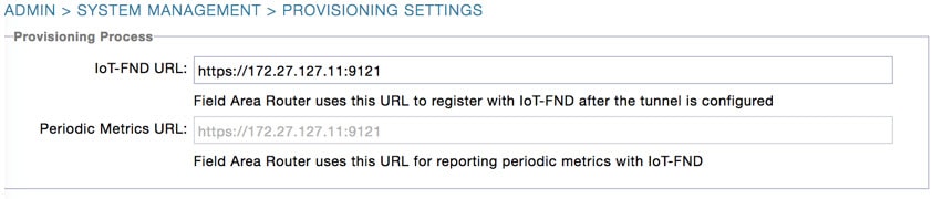
Visit FND URL https://<IP address from step 4>/ and change the password for root user. Default username/password is root/root123
Note : Change the ADMIN > SYSTEM MANAGEMENT > PROVISIONING SETTINGS > IOT FND URL with the FND IP address as shown in Provisioning Settings. Otherwise, registration may fail.
Figure 1 Provisioning Settings
Step 2: DHCP Option 43 Settings
If the IC3000 gateway gets an IP address from the DHCP server, Option 43 is used to advertise the FND IP address via DHCP.
Configure the following on an IR8x9:
Please make note of Option 43 usage:
■![]() If you have a DHCP server, use the “same” PNP discovery option string that we use for regular IOS routers Option 43 ascii “5A;K4;B2;I172.27.88.63;J9125" (IGMA will use port 9121 as default. IoT FND IP is 172.27.88.63)
If you have a DHCP server, use the “same” PNP discovery option string that we use for regular IOS routers Option 43 ascii “5A;K4;B2;I172.27.88.63;J9125" (IGMA will use port 9121 as default. IoT FND IP is 172.27.88.63)
■![]() If you wish to use a different port provide the following configuration:
If you wish to use a different port provide the following configuration:
option 43 ascii “5A;K4;B2;I192.168.10.6;J9125;W9128"
On a regular Linux server running DHCP, use the following instructions:
Step 3: Understanding the Device Configuration Template
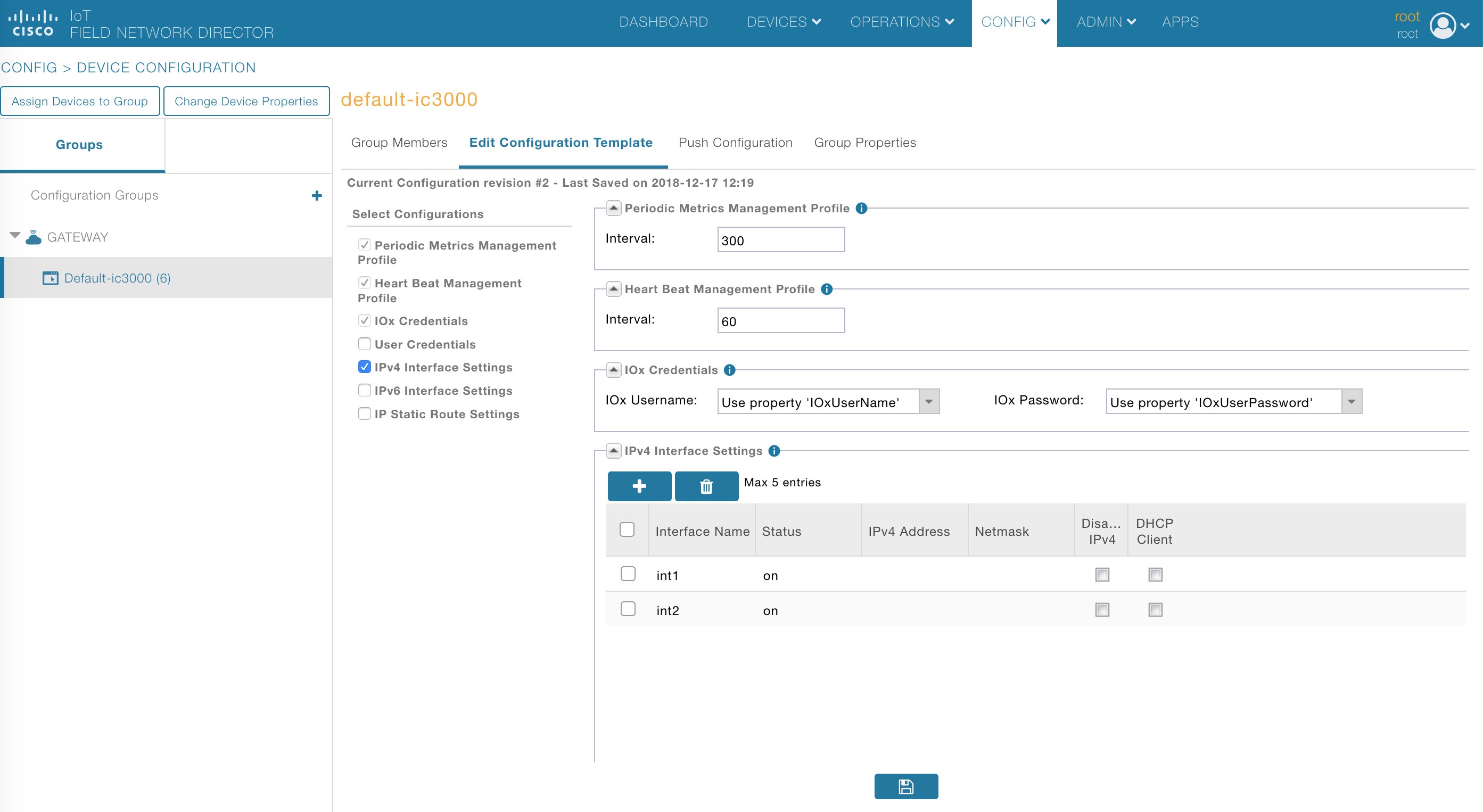
There is a default template within the FND for IC3000. It is located under CONFIG >Device Configuration tab > default-IC3000 > Edit Configuration template. See Step 4: Adding the IC3000 Gateway(s) to FND.
Edit the interface configuration or add interface settings as required by your use case. Once edited, use the Push Configuration tab to push the new configuration to the active or registered devices.
Note : It is important to make sure the map is correctly configured. If valid entries do not exist, you will get an error message like the on shown in Map Error.
Step 4: Adding the IC3000 Gateway(s) to FND
1.![]() Prepare a spreadsheet with the list of devices to add. This must be completed before adding devices to avoid additional steps.
Prepare a spreadsheet with the list of devices to add. This must be completed before adding devices to avoid additional steps.
Your spreadsheet will need the fields as shown in the following example:
Note : The eid is a combination of the PlatformID+HardwareID. The platform id for the IC3000 is always IC3000-2C2F-K9 and the HardwareID or Serial number is unique for each platform. The serial number can be read from the label on the box, or if you have access to the console of the device run the show version command and the hardware id /serial number will be displayed.
Note : The latitude (lat) and Longitude (lng) entries in the spreadsheet will need to represent actual values, complete with decimal notation. For latitude, a positive number represents North and a negative number represents South. For longitude, a positive number represents East and a negative number represents West. Failure to specify an actual value will result in an error being displayed from Google Maps.
Note : There are password restrictions for the IOxUserPassword.
The following password rules must be adhered to:
–![]() Must not be based upon a dictionary word
Must not be based upon a dictionary word
–![]() Must not be a combination of dictionary words
Must not be a combination of dictionary words
–![]() Must not be composed of common string patterns like “qwerty”, “asdfgh” etc...
Must not be composed of common string patterns like “qwerty”, “asdfgh” etc...
–![]() Must not be a combination of common string patterns and dictionary words
Must not be a combination of common string patterns and dictionary words
–![]() Currently not supporting Unicode
Currently not supporting Unicode
To download a sample spreadsheet click on the following link:
https://www.cisco.com/c/dam/en/us/td/docs/routers/ic3000/deployment/guide/IC3000-default-Input-template.csv
2.![]() Get the Serial number and Model number and use system as the ioxusername and admin as the password. The serial number is located on the device label and is something like "FOC2227Y304". The serial number can also be found through the show version command output:
Get the Serial number and Model number and use system as the ioxusername and admin as the password. The serial number is located on the device label and is something like "FOC2227Y304". The serial number can also be found through the show version command output:
3.![]() Click DEVICES > FIELD DEVICES > Inventory > Add Devices. Browse to the location of your excel spreadsheet and click Add. See Add Devices.
Click DEVICES > FIELD DEVICES > Inventory > Add Devices. Browse to the location of your excel spreadsheet and click Add. See Add Devices.
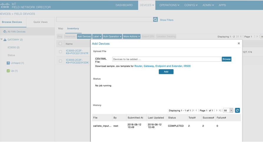
Note : The IC3000 belongs under the gateway category when adding devices.
Step 5: IC3000 Registration
After you add devices to the IoT FND (FND) Network Management application, wait for a few minutes for the IC3000 devices to learn the option 43 settings from the DHCP server, and then register with FND. Once the IC3000 gets an ip address from DHCP server, the option 43 issues an FND IP address for the device to register to FND.
Note : Make sure the DHCP server settings are set properly with FND IP in option 43 string.
Once the device is registered you should see the registration events listed for each IC3000 unit as shown in the example on Device Registration.
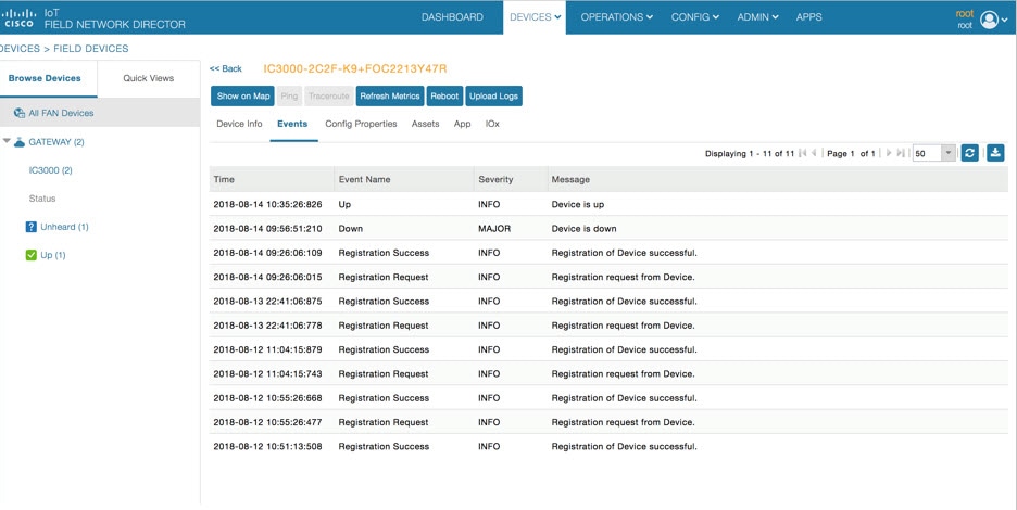
The refresh metric should work and should be able to refresh the device related details.
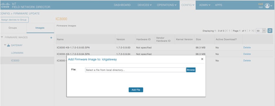
Step 6: Uploading the Firmware to FND
In order to upgrade the firmware of the IC3000, you must download the required firmware from Cisco.com to upload the firmware to FND.
Select CONFIG > Firmware Update > Images. A list of the IC3000 images is presented. Click + - and upload the required image. See Firmware Upload.
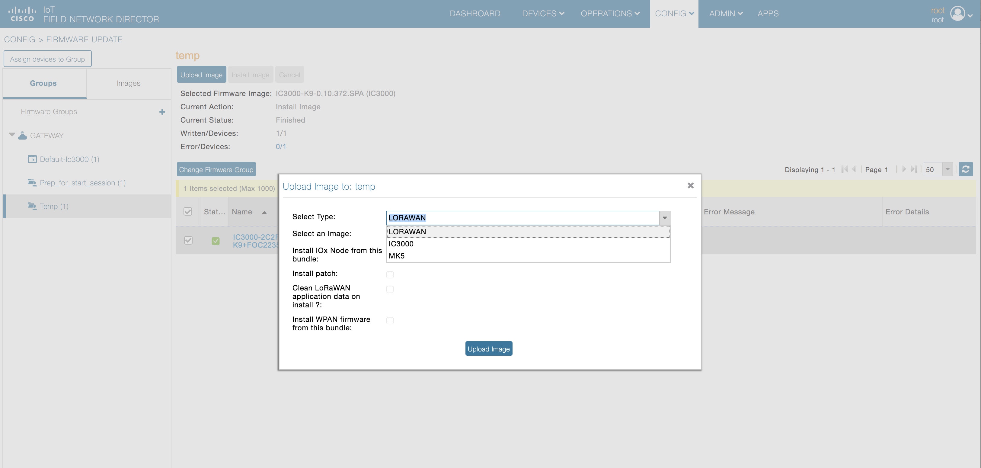
Step 7: Upgrading Firmware with FND
Once Step 5 is complete, you may now upgrade the firmware against the registered Units that require the update.
Select CONFIG > Firmware update > Select the device group > Upload Image
Once the Image upload is complete, select the Install Image tab and proceed with upgrading the firmware.
Step 8: Deploying the IOx Applications via FND
To deploy an IOx application perform the following:
1.![]() From the Main page select APP > Import Apps and select the required application to install.
From the Main page select APP > Import Apps and select the required application to install.
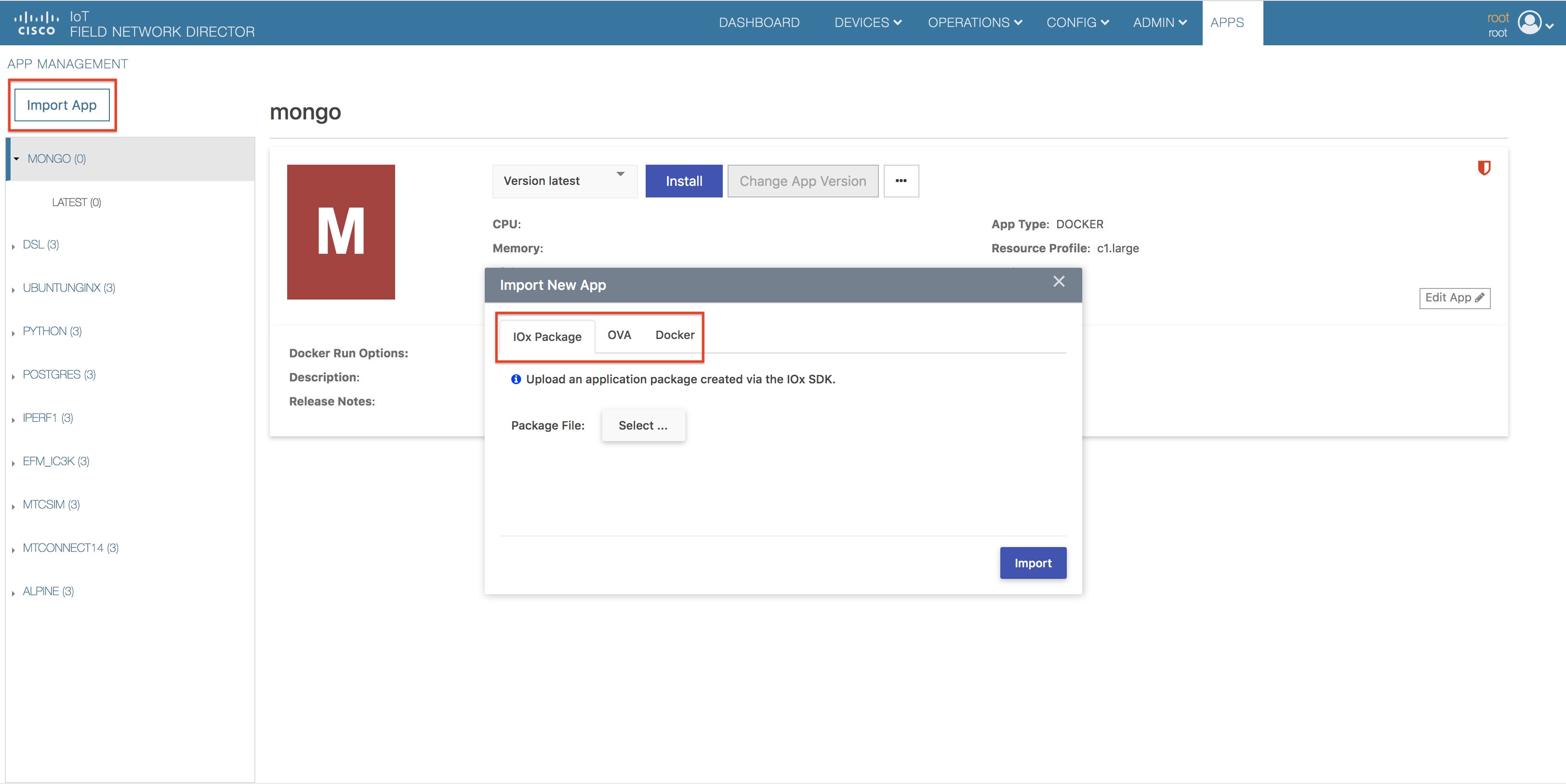
Once imported, you will find the list of applications imported in the right column.
2.![]() Select the application that needs to be installed and click Install.
Select the application that needs to be installed and click Install.
Note![]() : You can now import multiple versions of the same application (IoT FND 4.5 and greater)
: You can now import multiple versions of the same application (IoT FND 4.5 and greater)
3.![]() Select the Devices > Add Selected Devices. With your device present, click Next
Select the Devices > Add Selected Devices. With your device present, click Next
Select the appropriate actions and tabs and provide details as required. See Selected Device Action Tabs
Figure 10 Selected Device Action Tabs
4.![]() Then click Done, Let’s Go. The Installation progress window appears. See Installation Progress.
Then click Done, Let’s Go. The Installation progress window appears. See Installation Progress.
Figure 11 Installation Progress
If installation is successful, you should be able to see the installed count increasing. See Installation Successful.
Figure 12 Installation Successful
Phase 3: Developer Mode: Testing IOX Applications via Local Manager
Understanding Developer Mode
Typically, when connected to the IC3000 through a laptop, you are in developer mode. This mode is suitable for developers, system integrators or engineers who want to test or build an application, which is specific to their choice of use case, before deploying in large scale via FND. It is assumed that the IOX client utility can be used to package the application as a container or Docker. VM based APP support will be included in later releases.
Understanding Production Mode
This mode is typically when the IC3000 has been deployed in field, and actively performing in the field hosting apps that were prebuilt and designed to run. This mode must be managed by FND. The device management ports learn the DHCP address and gradually registers with FND. Please refer the IC3000 device registration section.
Developer Mode Connectivity
Consider the following points in order to connect to the IC3000 in developer mode:
■![]() Brand new devices (fresh from Cisco factory) have the capability of determining the mode autonomously depending on the networking configurations.
Brand new devices (fresh from Cisco factory) have the capability of determining the mode autonomously depending on the networking configurations.
■![]() Developer mode enables the Cisco IOx Local Manager interface which can be accessed via the browser on the computer connected to the gateway.
Developer mode enables the Cisco IOx Local Manager interface which can be accessed via the browser on the computer connected to the gateway.
■![]() Developer mode is activated ONLY over the management Ethernet port of the device.
Developer mode is activated ONLY over the management Ethernet port of the device.
■![]() Developer mode operates ONLY over a predetermined IPv4 Link-local addresses (169.254.x.x). You cannot use developer mode over a LAN/WAN.
Developer mode operates ONLY over a predetermined IPv4 Link-local addresses (169.254.x.x). You cannot use developer mode over a LAN/WAN.
■![]() Developer mode CANNOT be turned ON via FND.
Developer mode CANNOT be turned ON via FND.
■![]() An IC3000 deployed in production can be re-configured to operate in developer mode by pressing the "Reset" button on the device. All existing configuration information is removed on reset.
An IC3000 deployed in production can be re-configured to operate in developer mode by pressing the "Reset" button on the device. All existing configuration information is removed on reset.
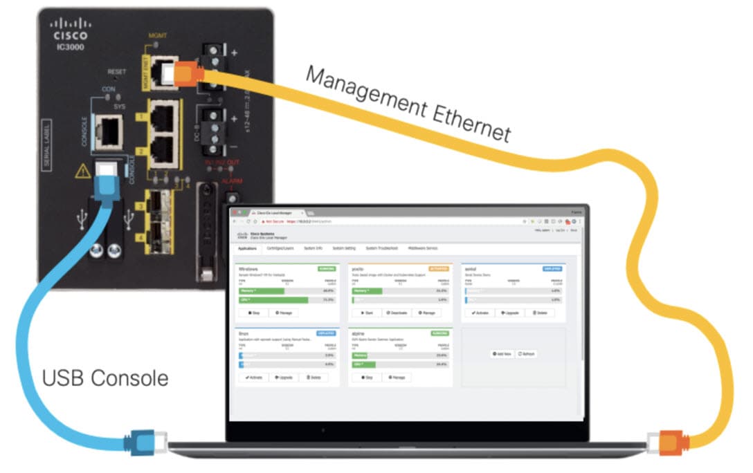
Steps to Connect to the Management Port
PC Connected to Management Interface shows a laptop connected to the management interface via a standard Ethernet cable.
Figure 13 PC Connected to Management Interface
|
|
|
|---|---|
1.![]() Follow steps 1-4 of Phase 1: Unboxing, Installing and Connecting to the IC3000 Device.
Follow steps 1-4 of Phase 1: Unboxing, Installing and Connecting to the IC3000 Device.
2.![]() Connect the Management interface on the IC3000 and your laptop with a console cable.
Connect the Management interface on the IC3000 and your laptop with a console cable.
3.![]() Do not power on the IC3000 yet.
Do not power on the IC3000 yet.
4.![]() Assign the IP address of 169.254.128.4 with a netmask of 255.255.0.0 to the network interface on your computer.
Assign the IP address of 169.254.128.4 with a netmask of 255.255.0.0 to the network interface on your computer.
Note : It is critical you assign this specific IPv4 link-local address.
6.![]() The IC3000 will be ready to operate in developer mode in 30 seconds (The delay of 30 seconds only occurs the first time a device is booted up. All subsequent reloads will immediately take the device to developer mode without delay).
The IC3000 will be ready to operate in developer mode in 30 seconds (The delay of 30 seconds only occurs the first time a device is booted up. All subsequent reloads will immediately take the device to developer mode without delay).
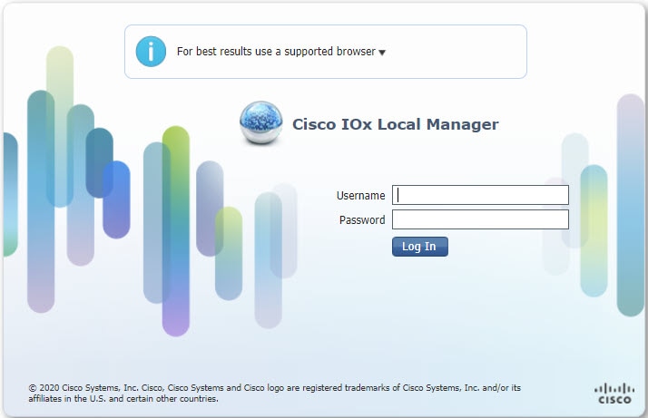
7.![]() Open a browser on your laptop and enter https://169.254.128.2:8443 as a URL. The Local Manager opens. Enter developer as your username and then create a password. Use the following commands to establish a password.
Open a browser on your laptop and enter https://169.254.128.2:8443 as a URL. The Local Manager opens. Enter developer as your username and then create a password. Use the following commands to establish a password.
Note : The following password rules must be adhered to:
–![]() Must not be based upon a dictionary word
Must not be based upon a dictionary word
–![]() Must not be a combination of dictionary words
Must not be a combination of dictionary words
–![]() Must not be composed of common string patterns like “qwerty”, “asdfgh” etc...
Must not be composed of common string patterns like “qwerty”, “asdfgh” etc...
–![]() Must not be a combination of common string patterns and dictionary words
Must not be a combination of common string patterns and dictionary words
–![]() Currently not supporting Unicode
Currently not supporting Unicode
8.![]() You can change an existing password using the following commands:
You can change an existing password using the following commands:
Upgrading the IC3000 Firmware with Local Manager
The following steps are used to upgrade the device firmware through the Local Manager GUI in Developer Mode.
1.![]() Login to LM GUI using the LLA address
Login to LM GUI using the LLA address
2.![]() Use the developer password previously created.
Use the developer password previously created.
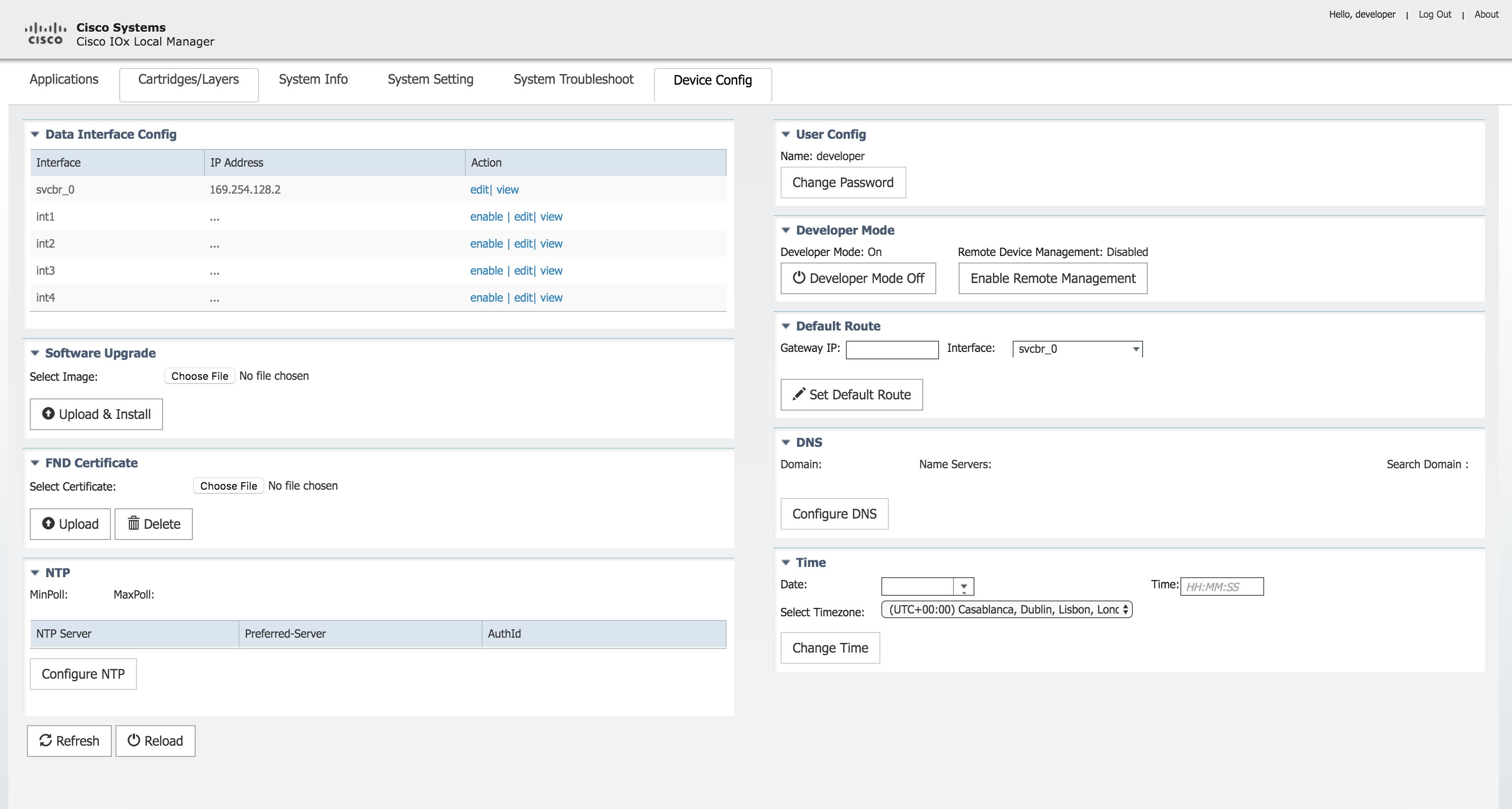
3.![]() Once you are logged into the GUI, click on the Device Config tab, then select the Software Upgrade. (See Device Config Tab).
Once you are logged into the GUI, click on the Device Config tab, then select the Software Upgrade. (See Device Config Tab).
4.![]() Select the image file and then click Upload & Install.
Select the image file and then click Upload & Install.
5.![]() If you receive any pop-up messages click OK.
If you receive any pop-up messages click OK.
6.![]() The image is pushed to the IC3000 and it is rebooted with the new firmware.
The image is pushed to the IC3000 and it is rebooted with the new firmware.
Phase 4: Connecting and Managing via Local Manager
About Local Manager
Cisco IOx Local Manager provides a web-based user interface that you can use to manage, administer, monitor, and troubleshoot applications on a device, and to perform a variety of related activities.
Accessing the IC3000 via Local Manager
Find the Management port address to access the IC3000 via a web browser. After connecting the IC3000 to a laptop, gather the svcbr_0 address whether you are in production mode, or developer mode. Use the show interfaces command to determine the IP address, or if you are managing the device via FND, get the device IP address. Use the ioxusername and ioxpassword to login via Local Manager, or you can create users on the IC3000 from the device configuration tab. Use the json commands to create users and passwords that Local Manger can use.
Note : If the IC3000 is in developer mode, you will be using an IPv4 LLA address of 169.254.128.x. The rest of the following work flow is the same.
1.![]() Open a web browser and enter https://169.254.128.2:8443 in the address bar.
Open a web browser and enter https://169.254.128.2:8443 in the address bar.
2.![]() Login by using the credentials developer/< your-password >. This is the password that was created by the developer set-password or developer change-password command. You should have various tabs that Local Manager supports, since you are accessing the unit via Local Manager. You should be familiar with the developer mode options like Device Config tab.
Login by using the credentials developer/< your-password >. This is the password that was created by the developer set-password or developer change-password command. You should have various tabs that Local Manager supports, since you are accessing the unit via Local Manager. You should be familiar with the developer mode options like Device Config tab.
If a security exception message appears in your browser, confirm the exception to continue to the Cisco IOx Local Manager Login screen.
If you see the message "For best results use a supported browser" near the top of this screen, your browser may have compatibility issues with this version of Cisco IOx Local Manager. In this case, we recommend that you load a compatible browser. Hover your mouse pointer over the down-arrow next to this message to see a list of compatible browsers as shown in Supported Browsers.
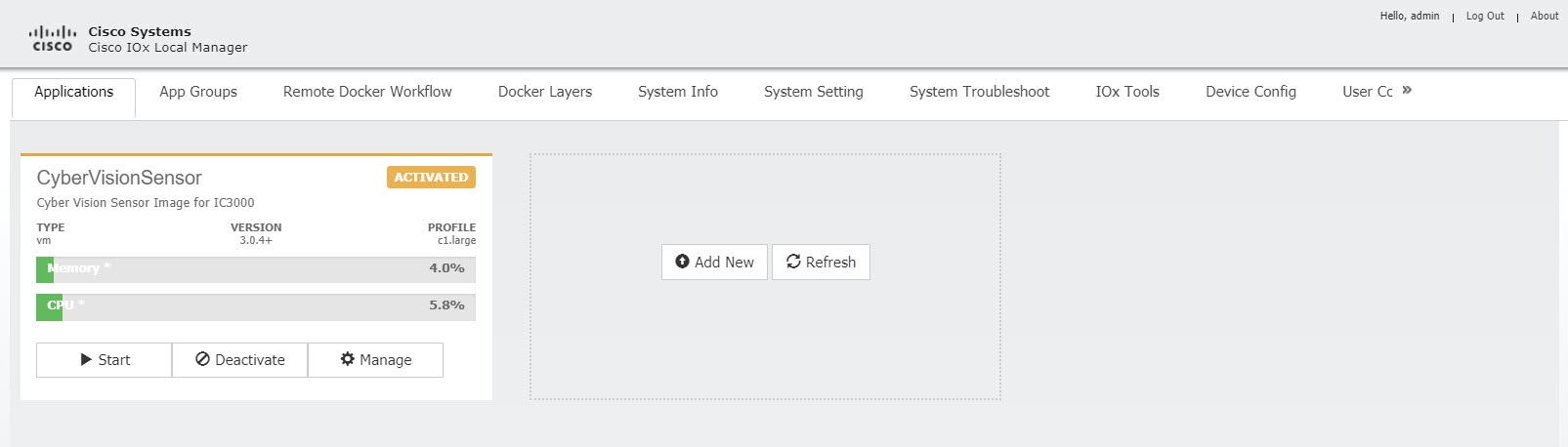
The Local Manager Applications Tab appears. See Local Manager Applications Tab.
Figure 16 Local Manager Applications Tab
4.![]() Your IC3000 is now ready for Cisco IOx application development.
Your IC3000 is now ready for Cisco IOx application development.
Use Case Example: Installing a Prebuilt Application via Local Manager
This section shows you how to use Cisco IOx Local Manager to load a sample EFM application and how to run the application.
1.![]() Download the LXC or Docker application on to your desktop. Go to the following link:
Download the LXC or Docker application on to your desktop. Go to the following link:
https://software.cisco.com/download/home/286316104/type/286312892/release/1.5.0
2.![]() In the Cisco IOx Local Manager Applications Tab, click Add New. The Deploy application dialog box appears, see Deploy application.
In the Cisco IOx Local Manager Applications Tab, click Add New. The Deploy application dialog box appears, see Deploy application.
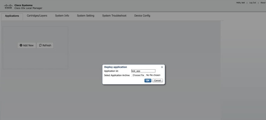
3.![]() In the Deploy Application dialog box, take these actions:
In the Deploy Application dialog box, take these actions:
a.![]() In the Application ID field, enter a name.
In the Application ID field, enter a name.
b.![]() In the Select Application Archive field, click Choose File and navigate to, then select the sample application file that you downloaded in Step 1.
In the Select Application Archive field, click Choose File and navigate to, then select the sample application file that you downloaded in Step 1.
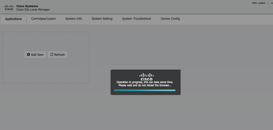
4.![]() The application file uploads to Cisco IOx. See Upload Operation Window
The application file uploads to Cisco IOx. See Upload Operation Window
Note : Do NOT refresh the browser during the upload.
Figure 18 Upload Operation Window
5.![]() When you see the pop-up message "Successfully Deployed”, click OK.
When you see the pop-up message "Successfully Deployed”, click OK.
Figure 19 Application Successfully Deployed
The Cisco IOx Local Manager Applications tab updates to show the EFM application area.
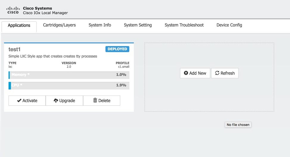
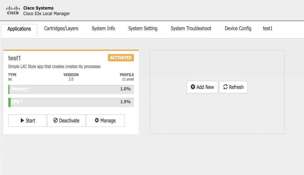
6.![]() In the test1/APP area, click the Activate button. The Applications > Resources tab displays, see Applications > Resources Tab.
In the test1/APP area, click the Activate button. The Applications > Resources tab displays, see Applications > Resources Tab.
Figure 20 Applications > Resources Tab
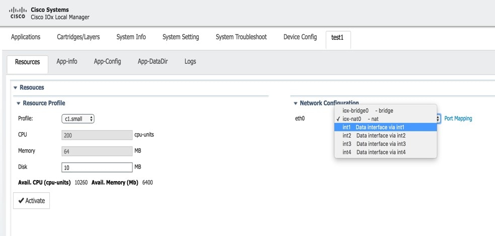
7.![]() In the Network Configuration area of the Applications > Resources tab, perform the following:
In the Network Configuration area of the Applications > Resources tab, perform the following:
a.![]() Choose int1 Default Network from the eth0 drop-down list.
Choose int1 Default Network from the eth0 drop-down list.
b.![]() Choose int2 from the eth1 drop down list.
Choose int2 from the eth1 drop down list.
Note : Always use eth1 to connect your device to your local network.
8.![]() While still in the Applications > Resources tab, click the Activate button to activate the application.
While still in the Applications > Resources tab, click the Activate button to activate the application.
9.![]() Click the Applications tab.
Click the Applications tab.
10.![]() In the EFM area, click the Start button. See Applications > Start.
In the EFM area, click the Start button. See Applications > Start.
Note : Make sure that activated the application before clicking Start.
Figure 21 Applications > Start
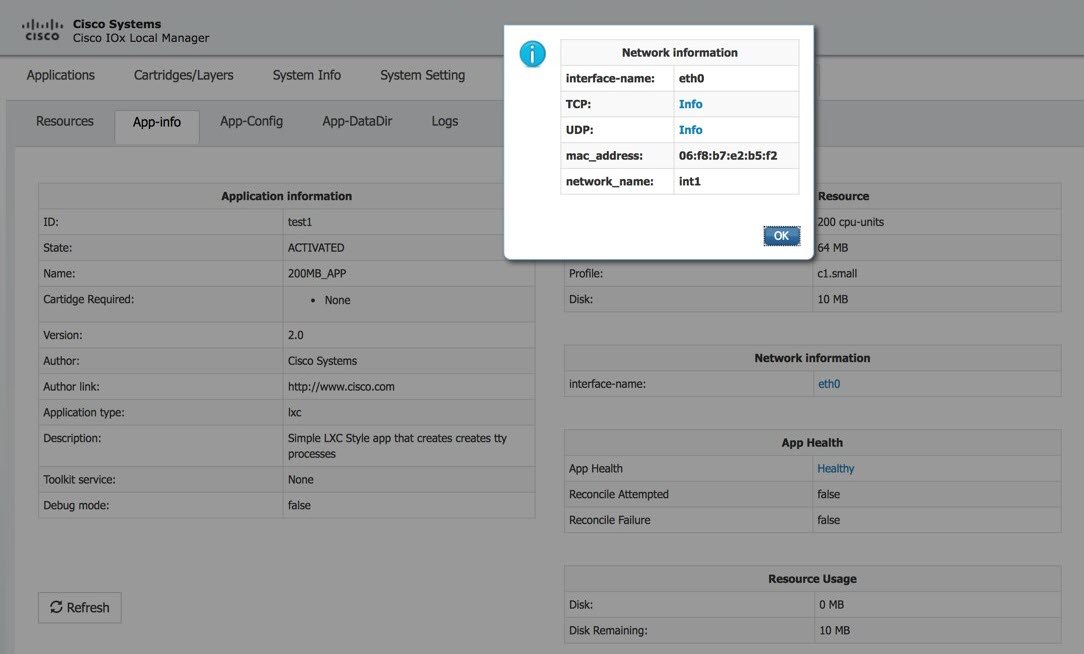
11.![]() Click the App-info tab and make sure that data ports int1 and int2 are up. Then, once the application is started check the dhcp obtained address in the App-info tab. See App-info Tab.
Click the App-info tab and make sure that data ports int1 and int2 are up. Then, once the application is started check the dhcp obtained address in the App-info tab. See App-info Tab.
Additional Examples
There are a number of applications that can be loaded onto the IC3000. Developers can package any application as long as it is in a container or VM. Additional information and examples are located on DevNet documentation on IOx. Provides an overview as well as details by scrolling down the left hand side:
Remote Device Management
The remote device management feature provides the user with the ability to enable or disable the remote access to the device configuration page from Cisco IOx Local Manager over a non-link local address.
Note : Remote Device Management is new with Local Manager version 1.8. If your device is still running version 1.7, you will need to upload the new image. See Step If required, upload the new Image from the Device Config tab and it will reload the device with the latest image. below.
The procedure to bring the IC3000 up into Developer Mode remains exactly same as previously described in Phase 3: Developer Mode: Testing IOX Applications via Local Manager. Use the pre-defined link-local address169.254.128.2 to get the device up in developer mode.
Next, follow these additional steps to enable remote device management:
1.![]() If required, upload the new Image from the Device Config tab and it will reload the device with the latest image.
If required, upload the new Image from the Device Config tab and it will reload the device with the latest image.
2.![]() Open a NEW browser and login again with the 169.254.128.2 address to the Local Manager using developer credentials.
Open a NEW browser and login again with the 169.254.128.2 address to the Local Manager using developer credentials.
Note : The old browser is now non-functional.
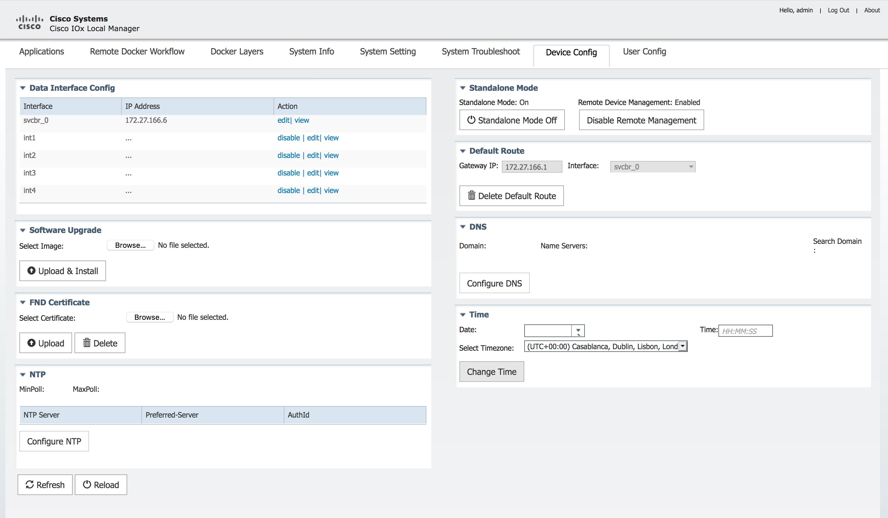
3.![]() In the Device Config tab there is a new section on the right side called “Remote Device Management”. See the highlighted area in Remote Device Management.
In the Device Config tab there is a new section on the right side called “Remote Device Management”. See the highlighted area in Remote Device Management.
Figure 23 Remote Device Management
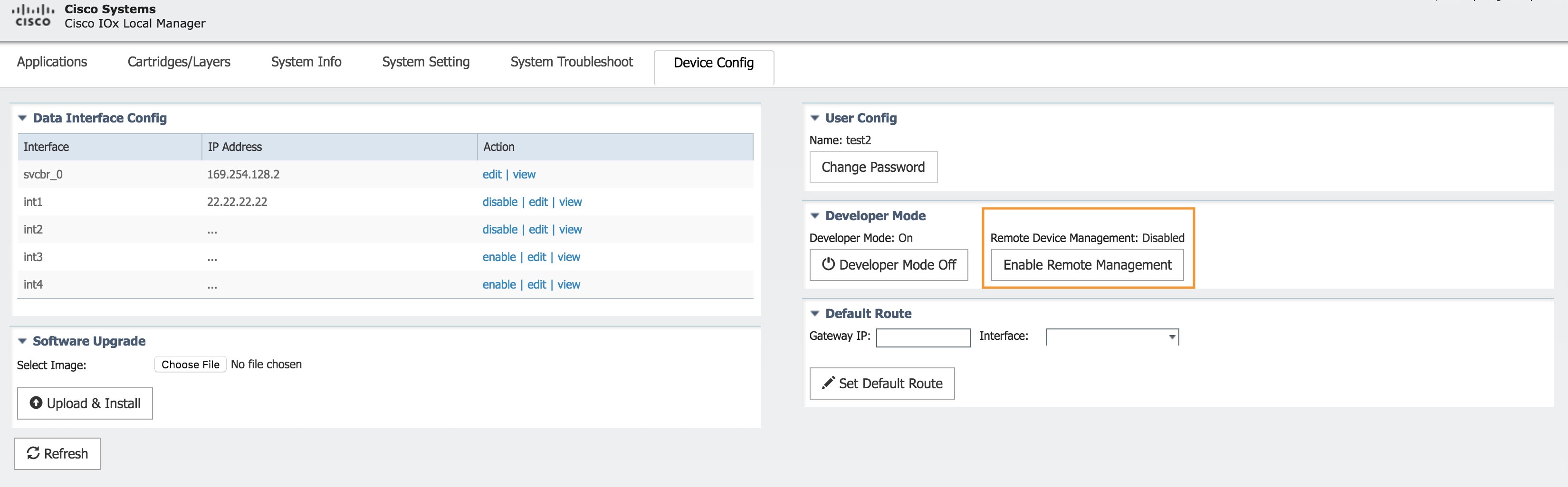
4.![]() Click Enable Remote Management, and then respond with Yes/Okay for any pop-ups.
Click Enable Remote Management, and then respond with Yes/Okay for any pop-ups.
After enabling remote device management, the user can access the device configuration page from any IP address other than the link local address.
Note : Since the HTTP server is not only binding with the link local IP address, the user can access the device config page from the data port as long as it has routable IP address configured with an up state.
5.![]() Use the https:// <new address> :8443 in a new browser window to login to LM using developer credentials.
Use the https:// <new address> :8443 in a new browser window to login to LM using developer credentials.
See Remote Device Management (Enabled) for guidance for these steps.
6.![]() Make sure you are aware of your network topology (static ip address or DHCP) for the management interface svcbr_0.
Make sure you are aware of your network topology (static ip address or DHCP) for the management interface svcbr_0.
If the address is non link local address other than 169.x.x.x:
a.![]() Edit the svcbr_0 address to <your ip address> and make sure to add a network on the laptop to connect to the Local Manager.
Edit the svcbr_0 address to <your ip address> and make sure to add a network on the laptop to connect to the Local Manager.
b.![]() Use the new address from the browser to login to the Local Manager with developer credentials.
Use the new address from the browser to login to the Local Manager with developer credentials.
If the address is a static routable address:
a.![]() Obtain the default-route details and add the Gateway IP route details to the svcbr_0 interface below" Default Route" section below
Obtain the default-route details and add the Gateway IP route details to the svcbr_0 interface below" Default Route" section below
b.![]() On the left side of the Device Config screen, edit the svcbr_0 interface, static option,with chosen IP address and set mask. Click Ok.
On the left side of the Device Config screen, edit the svcbr_0 interface, static option,with chosen IP address and set mask. Click Ok.
c.![]() Attach the MGMT port to the network where the address is reachable.
Attach the MGMT port to the network where the address is reachable.
Note : The Local Manager is not reachable anymore once the configuration is pushed, you have to connect the MGMT port of the IC3000 to a network where the address is reachable.
d.![]() Use the new chosen address from a new browser window to login into Local Manager with the developer credentials.
Use the new chosen address from a new browser window to login into Local Manager with the developer credentials.
If the MGMT/svcbr_0 is connected to a DHCP network, after enabling remote management edit the svcbr_0 interface to select the DHCP option.
a.![]() Disconnect IC3000 mgmt port from laptop and connect to the network for active DHCP learning on svcbr_0.
Disconnect IC3000 mgmt port from laptop and connect to the network for active DHCP learning on svcbr_0.
b.![]() Check the ip address learned via DHCP on the platform console using the CLI show interfaces.
Check the ip address learned via DHCP on the platform console using the CLI show interfaces.
c.![]() Use the https:// <new address> :8443 in a new browser window to login to LM using developer credentials.
Use the https:// <new address> :8443 in a new browser window to login to LM using developer credentials.
7.![]() Obtain the default-route details and add the Gateway IP route details to the svcbr_0 interface below Default Route.
Obtain the default-route details and add the Gateway IP route details to the svcbr_0 interface below Default Route.
8.![]() On the left side of the Device Config screen, edit the svcbr_0 interface with chosen IP address and mask. Click Ok
On the left side of the Device Config screen, edit the svcbr_0 interface with chosen IP address and mask. Click Ok
9.![]() See Remote Device Management (Enabled) for guidance for these steps.
See Remote Device Management (Enabled) for guidance for these steps.
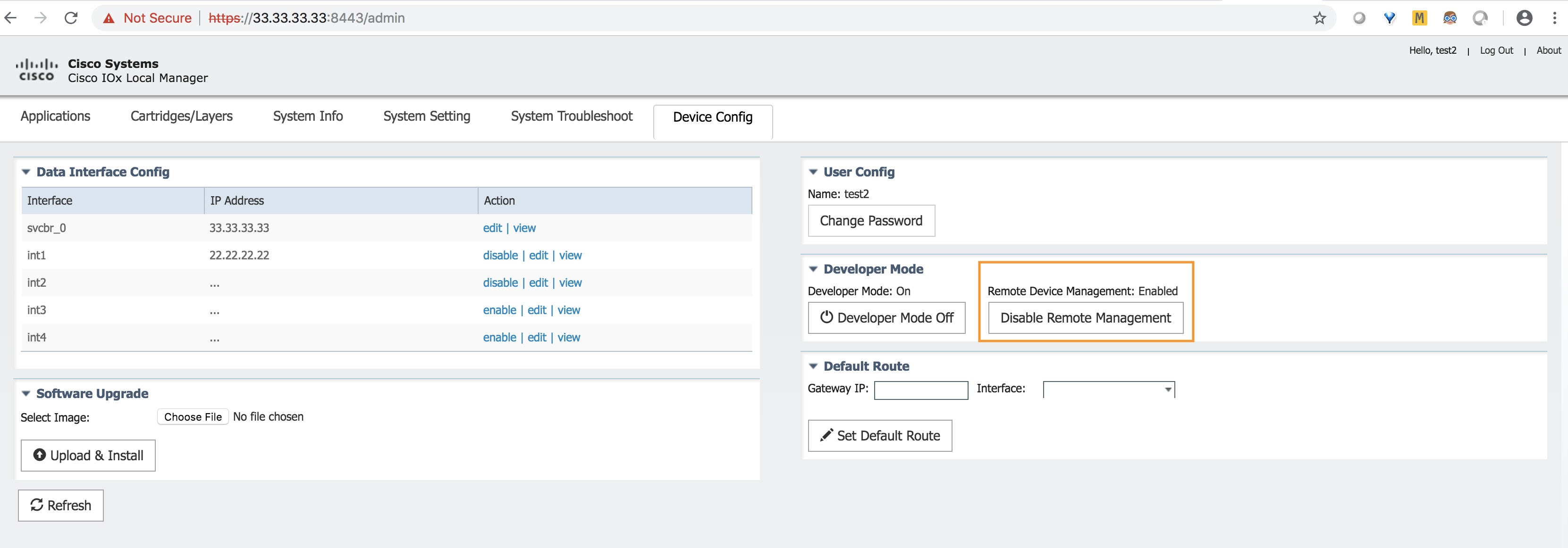
Figure 24 Remote Device Management (Enabled)
To disable remote device management
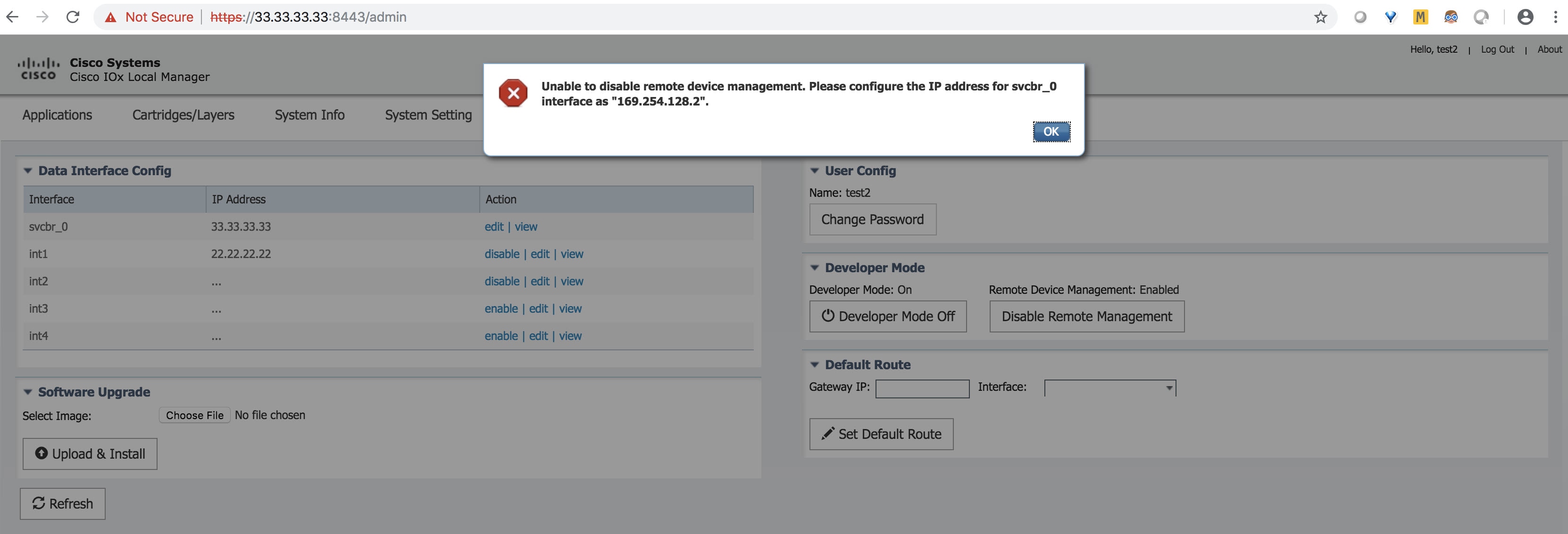
From the same Device Config tab window, you can see the Remote Device Management section status has toggled to “Enabled”. To disable the feature, click Disable Remote Management.
Disabling the remote device management feature will bind the server back to the 169.254.128.2 address of the link local manager. The user will not be allowed to disable the remote device management unless they change the IP address for "svcbr_0" back to 169.254.128.2.
Figure 25 Disable Remote Device Management Warning
Additional Administration
The following are some of the additional items to consider as an administrator:
IC3000 Image Installation
The IC3000 is shipped with a factory installed image. Once the device is powered up the version installed can be verified by running the show version command via the console. If the version is the latest CCO version, or a recommended version, you may continue with your next steps.
The version string shown in the example is a representation of the CCO download image C3000-K9-1.0.1.SPA.
If the version is an older version and needs to be upgraded, then please download the latest version from CCO site and update the firmware using LM or FND.
Choose LM or FND as a preference of choice. For example, if you are accessing the device locally connected to a PC, then you may be able to use LM to upgrade the firmware. If you are managing a number of IC3000 devices via FND, then you should be able to use the firmware update tab in FND to upgrade the firmware.
The LM work flow is as follows:
1.![]() Connect the IC3000 to a laptop or use the svcbr_0 interface address and access the LM via the following URL: https:// <ipaddress> :8443
Connect the IC3000 to a laptop or use the svcbr_0 interface address and access the LM via the following URL: https:// <ipaddress> :8443
2.![]() Select the Device Config tab, then click the Choose File button in the Software Upgrade section to select the image file. See Device Config Tab. Click the Upload & Install button to upload the image. Note that the device will be rebooted after the new image is installed.
Select the Device Config tab, then click the Choose File button in the Software Upgrade section to select the image file. See Device Config Tab. Click the Upload & Install button to upload the image. Note that the device will be rebooted after the new image is installed.
Note : the device configuration tab will not be enabled in standalone mode. You should be in developer mode to access the device configuration tab and this can be achieved by factory resetting the box.
The FND work flow is as follows:
Please follow the Step 7: Upgrading Firmware with FND procedure.
Note : The reboot time is approximately 3 minutes and the size of the firmware is roughly 100MB. It could take 5 to 6 minutes for the IC3000 to upgrade the firmware. The CAF or IGMA will be upgraded as well, and will be automatically loaded and running once the device is up. There is no upgrade needed for CAF.
SSH Access
SSH access is disabled by default to prevent unauthorized access to the device. However, you can troubleshoot an application while you are in developer mode. The application console is enabled in developer mode. If developer mode is off, the application console access is disabled.
Audit Trail for Application Management Operations
Note: This functionality is only supported in the IoT FND and Fog Director Integrated Solution.
The following two Application Management operations will generate an Audit Log:
Note![]() : There is no audit trail to track when you import or delete an application to or from the IoT FND and Fog Director Integrated Solution.
: There is no audit trail to track when you import or delete an application to or from the IoT FND and Fog Director Integrated Solution.
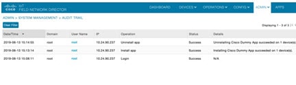
To view the Audit Log details, choose ADMIN > SYSTEM MANAGEMENT > AUDIT TRAIL.
Note: You can now import multiple versions of the same application.
Troubleshooting
This section provides some tips for troubleshooting problems that may occur.
IC3000 Related
Use the following commands from the console to determine the status of running applications.
■![]() To view which version of software the device is running:
To view which version of software the device is running:
■![]() To view whether the device is running developer mode or production mode:
To view whether the device is running developer mode or production mode:
■![]() To display debugging information when working with support:
To display debugging information when working with support:
Examples of Show Commands
Local Manager Related
The Local Manager GUI provides some details on your device status.
■![]() To debug Application status use the APP Tab
To debug Application status use the APP Tab
■![]() To download APP logs go to the APP Tab > Manage APP > APP-Dir or App-Logs and download the logs.
To download APP logs go to the APP Tab > Manage APP > APP-Dir or App-Logs and download the logs.
■![]() To view Application failure issues go to the System Troubleshooting Tab and look for events or errors.
To view Application failure issues go to the System Troubleshooting Tab and look for events or errors.
■![]() To turn off the Developer Mode, go to Device-Config > Developer Mode Off.
To turn off the Developer Mode, go to Device-Config > Developer Mode Off.
FND Related
If your device is not registering with FND, check the following:
■![]() Check the option 43 address format, and validate if it is the correct ip address of FND
Check the option 43 address format, and validate if it is the correct ip address of FND
■![]() Check the platform show ida status and show interfaces status to see which ip address the device has learned.
Check the platform show ida status and show interfaces status to see which ip address the device has learned.
■![]() Check the FND provisional setting URL to ensure FND IP address:9121
Check the FND provisional setting URL to ensure FND IP address:9121
■![]() Check whether the serial number in the FND input file is accurate
Check whether the serial number in the FND input file is accurate
FND Logs
See the following table for details on the location and names of FND log files.
See the following table for details on the location and names of FD log files.
Appendix: FND 4.3 device-configuration templates (Deprecated)
Understand the default values and select the other parameters as required and save the template. Use the (i) button to understand the optional and mandatory parameters.
Once complete, push the configurations to the devices using the Push Configuration tab on the top of the window.
Figure 28 Edit Configuration Template
For the FND 4.3.1 release and greater, the JSON formats for editing a particular IC3000 device are as follows:
To download a text file with clean JSON entries, go here:
https://www.cisco.com/c/dam/en/us/td/docs/routers/ic3000/deployment/guide/IC3000-JSON.txt
Note : Make sure your JSON is validated properly before pushing the configuration to device. It is highly recommended to use a JSON validator such as this one:
Copy and paste your entire device configuration template and see if its set appropriately. Anything that’s commented has to be removed before validation.
A typical comment section in json is between the following characters.
As an example, a working JSON entry for bringing all the interface up on IC3000 is as follows.
Appendix: Installing Cisco IoT Field Network Director (Cisco IoT FND)
This section provides the steps required to install the Cisco IoT Field Network Director (Cisco IoT FND) Release 4.3.1 and greater application with Integrated Application Management (Fog Director) on an Open Virtual Appliance (OVA), VMware ESXi 5.5 or 6.0. You use the same instructions to install both VMware versions.
Note: For information about installing Cisco IoT FND and Oracle on an OVA for Release 4.3 and greater, refer to the following guides:
Cisco IoT FND Deployment on an Open Virtual Appliance, VMware ESXi 5.5/6.0
Cisco IoT Field Network Director Installation Guide-Oracle Deployment, Releases 4.3.x, 4.4.x and 4.5.x
For an overview of the features and functionality of the IoT FND application and details on how to configure features and manage Cisco IoT FND after its installation, refer to the Cisco IoT Field Network Director User Guide for your current FND release (4.3.x, 4.4.x or 4.5.x)
Prerequisites
■![]() Access to the VMware ESXi server.
Access to the VMware ESXi server.
–![]() Contact your IT administrator to obtain the IP address to the VMware ESXi server.
Contact your IT administrator to obtain the IP address to the VMware ESXi server.
–![]() If you are installing the VMware ESXi server software yourself, go to the VMware ESXi site to download the software: https://www.vmware.com/products/esxi-and-esx.html
If you are installing the VMware ESXi server software yourself, go to the VMware ESXi site to download the software: https://www.vmware.com/products/esxi-and-esx.html
■![]() Install the VMware vSphere Client for the ESXi 5.5 or 6.0 server.
Install the VMware vSphere Client for the ESXi 5.5 or 6.0 server.
■![]() Locate the VMware credentials to create virtual machines in ESXi 5.5. or 6.0, respectively.
Locate the VMware credentials to create virtual machines in ESXi 5.5. or 6.0, respectively.
■![]() Ensure that you meet the VMware server machine requirements. Listed below are the VM CPU and memory requirements for a small scale deployment:
Ensure that you meet the VMware server machine requirements. Listed below are the VM CPU and memory requirements for a small scale deployment:
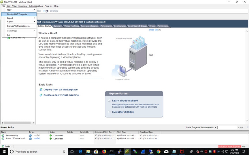
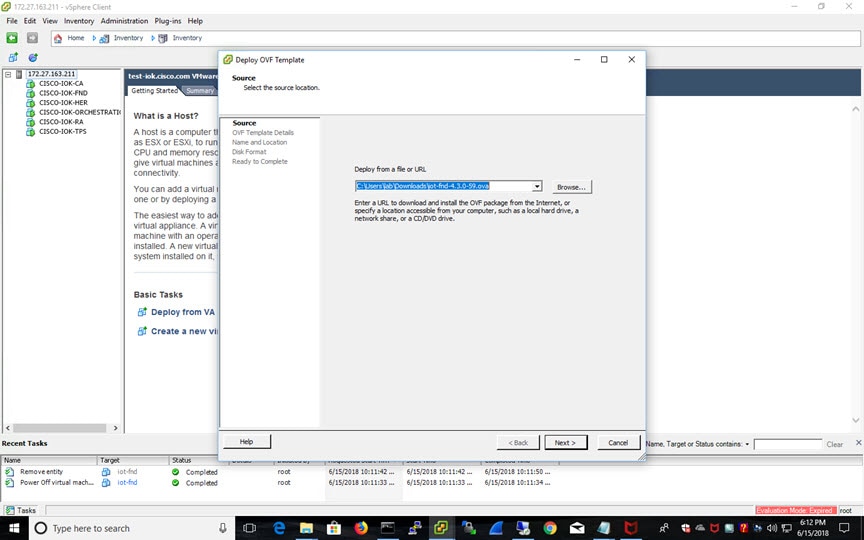
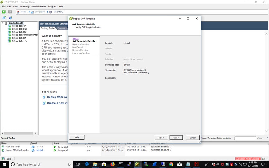
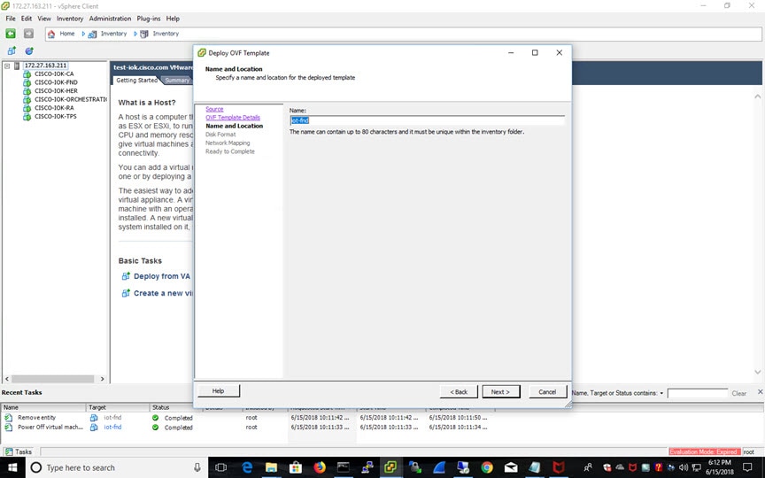
Installing the OVA
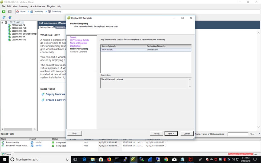
1.![]() Use VMware Fusion or VMware vSphere client to deploy OVA on ESXi Server. Do not change the defaults for the installation.
Use VMware Fusion or VMware vSphere client to deploy OVA on ESXi Server. Do not change the defaults for the installation.
a.![]() Under File, choose Deploy OVF template.
Under File, choose Deploy OVF template.
b.![]() Keep the default location and click Next.
Keep the default location and click Next.
d.![]() Enter a name of the deployed template.
Enter a name of the deployed template.
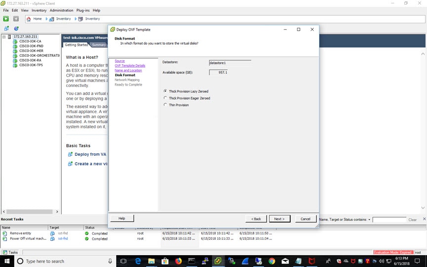
e.![]() Choose the format that you want virtual disks to be stored.
Choose the format that you want virtual disks to be stored.
Note: Thick provisions require 600 GB of disk space on the ESXi server.
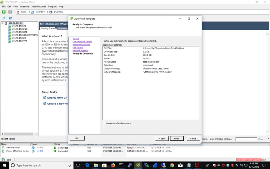
The template starts downloading. When it is completed, the template is listed on the left pane.
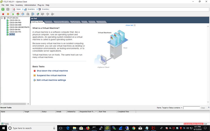
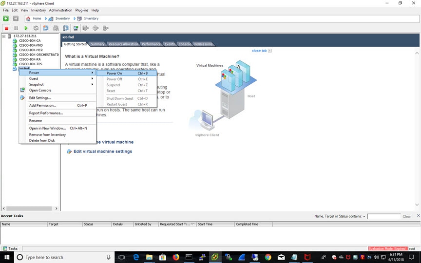
2.![]() Power on the VM. Right click on the iot-fnd template name. Select Power and Power On.
Power on the VM. Right click on the iot-fnd template name. Select Power and Power On.
3.![]() Assign a static IP address. Or, setup a DHCP server in the network, so an IP address gets assigned.
Assign a static IP address. Or, setup a DHCP server in the network, so an IP address gets assigned.
Setup a valid, reachable working DNS server on the Host VM. (mandatory)
Use this IP address to access the FND GUI.
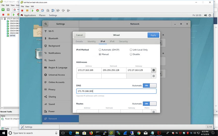
4.![]() Click on Console and login with root/cisco123 once the OS is up.
Click on Console and login with root/cisco123 once the OS is up.
a.![]() Once logged in, navigate to Applications -> System Tools ->Settings ->Network.
Once logged in, navigate to Applications -> System Tools ->Settings ->Network.
5.![]() From a web browser, access FND URL and change the password for the root user. Default username/password is root/root123.
From a web browser, access FND URL and change the password for the root user. Default username/password is root/root123.
6.![]() Open a terminal window, and setup Health Monitoring for the Fog Director Container from FND.
Open a terminal window, and setup Health Monitoring for the Fog Director Container from FND.
[root@iot-fnd ~]# cd /opt/monitor/
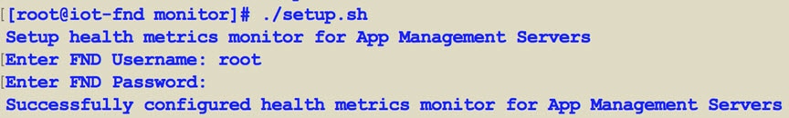
After completing these steps, FND starts monitoring Fog Director container on the ADMIN → SERVERS page.
Using a Custom cgms_keystore in the FND Container
Enter the following information to provide a secure connection to devices within this OVA deployment.
Use these steps to have FND use your custom keystore.
1.![]() Put your cgms_keystore file in /opt/fnd/data/ on the Host.
Put your cgms_keystore file in /opt/fnd/data/ on the Host.
2.![]() Run the following command to encrypt the password for the new cgms_keystore:
Run the following command to encrypt the password for the new cgms_keystore:
docker exec -it fnd-container /opt/cgms/bin/encryption_util.sh encrypt < keystore password >
3.![]() Modify the cgms.properties file in the /opt/fnd/data folder, and edit the following line to set the new encrypted cgms_keystore password:
Modify the cgms.properties file in the /opt/fnd/data folder, and edit the following line to set the new encrypted cgms_keystore password:
cgms-keystore-password-hidden=encrypted new cgms_keystore password
Note: With OVA 4.3.1 and above you can leave the cgms_keystore.selfsigned default bundled keystore untouched.
If both the files (cgms_keystore and cgms_keystore.selfsigned) are present, the cgms_keystore will be used by the container.
Configuring FND for IPv6 Tunnel Provisioning and Registration
FND OVA supports only IPv4 tunnels and Registration out of the box.
To setup an IPv6 network for tunnel provisioning and registration, follow these steps:
1.![]() Ensure you have one interface with a valid IPv6 network which has a IPv6 prefix length less than125.
Ensure you have one interface with a valid IPv6 network which has a IPv6 prefix length less than125.
See the following example of the ens32 interface:
2.![]() Run the./setup-IPv6-network.sh script in the /opt/fnd/scripts directory to obtain the FND IPv6 address on the router for tunnel provisioning and registration.
Run the./setup-IPv6-network.sh script in the /opt/fnd/scripts directory to obtain the FND IPv6 address on the router for tunnel provisioning and registration.
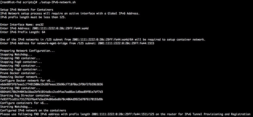
Note: While specifying the IPv6 address for the network-mgmt-bridge, provide an Interface Name and a valid IPv6 address (and IP address prefix length) that is in the subnet of the provided host interface. If IPv6 address is in a different subnet, the IPv6 tunnel provisioning and registration will not be successful.
Installing Custom CA Certificates on FND
By default the FND container comes bundled with cgms_keystore.
■![]() Keystore Location in the FND Container: /opt/cgms/server/cgms/conf/
Keystore Location in the FND Container: /opt/cgms/server/cgms/conf/
■![]() Default Trusted Certification Entry in Keystore: cisco_sudi, jmarconi
Default Trusted Certification Entry in Keystore: cisco_sudi, jmarconi
To use a custom CA certificate on the router, add a CA certificate to the trusted certificate entries in the cgms_keystore.
1.![]() Place the certificate file in the following location on the host machine.
Place the certificate file in the following location on the host machine.
docker exec -i -t fnd-container /bin/bash
3.![]() Change into the conf directory.
Change into the conf directory.
cd /opt/cgms/server/cgms/conf/
4.![]() Import a root or intermediate CA certificate to cgms_keystore.
Import a root or intermediate CA certificate to cgms_keystore.
/opt/cgms/jre/bin/keytool -import -trustcacerts -alias alias-name -file /tmp/fnd-data/ca.crt -keystore cgms_keystore
6.![]() Verify that the certificate was added to the trusted entry.
Verify that the certificate was added to the trusted entry.
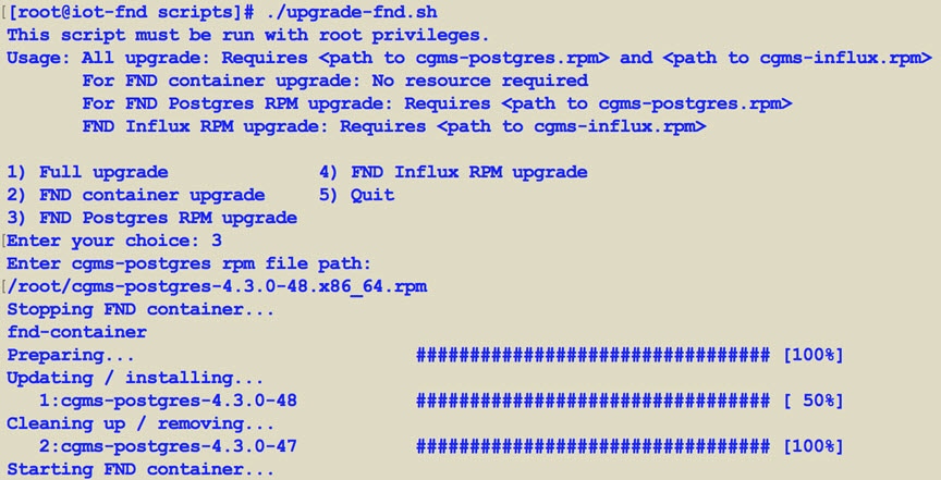
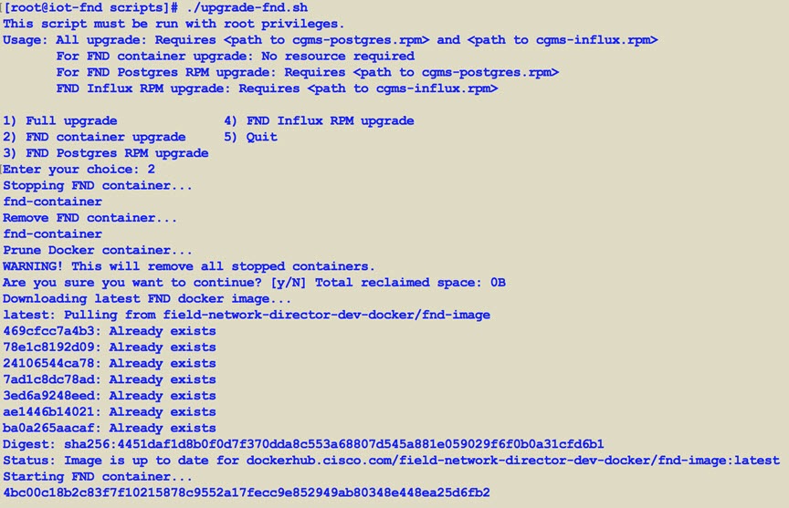
Upgrading FND
To update FND, you must have access to dockerhub.cisco.com.
Run the upgrade-fnd.sh script from the following directory:
The following examples show the upgrade process which includes upgrading cgms-postgres.rpm and cgms-influx.rpm.
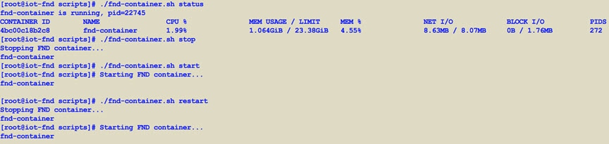
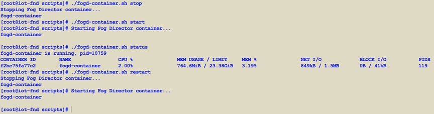
Starting and Stopping FND
Use the fnd-container.sh {start|stop|status|restart} script in the following directory to start, stop, obtain status, and restart FND:
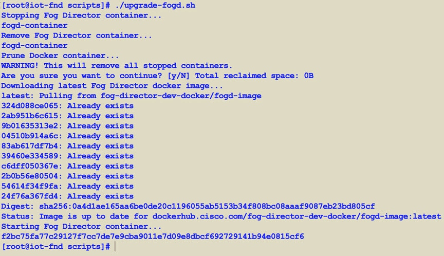
Upgrading Fog Director
To update Fog Director, you must have access to dockerhub.cisco.com.
Run the upgrade-fogd.sh script from the following directory:
Starting and Stopping Fog Director
Use the fogd-container.sh {start|stop|status|restart} script in the following directory to start, stop, obtain status, and restart Fog Director:
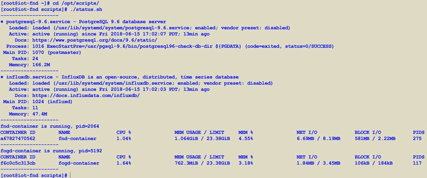
Obtaining Status of All Services Running on the Host
Use the status.sh script in the following directory to show the status of all services running on the host.
Upgrading Both Fog Director and FND
Use the upgrade.sh script in the following directory to fully upgrade both Fog Director and FND.
Note: Since this performs a full FND upgrade, you must provide the paths to cgms-postgres.rpm and cgms-influx.rpm
Backup and Restore
You can export the entire OVA image file as backup, port it to different deployment or restore from an older image file.
1.![]() Power down the OVA in vSphere Client.
Power down the OVA in vSphere Client.
2.![]() Select the OVA, and then select File -> Export -> Export OVF Template.
Select the OVA, and then select File -> Export -> Export OVF Template.
Setting the Time and Timezone Using NTP Service
Use the timedatectl command on the Host VM to perform following operations to sync the time between the host and the docker:
■![]() Displaying the Current Date and Time: timedatectl
Displaying the Current Date and Time: timedatectl
■![]() Changing the Current Time: timedatectl set-time HH:MM:SS
Changing the Current Time: timedatectl set-time HH:MM:SS
■![]() Changing the Current Date: timedatectl set-time YYYY-MM-DD
Changing the Current Date: timedatectl set-time YYYY-MM-DD
■![]() Listing the Time Zone: timedatectl list -timezones
Listing the Time Zone: timedatectl list -timezones
■![]() Changing the Time Zone: timedatectl set-timezone time_zone
Changing the Time Zone: timedatectl set-timezone time_zone
■![]() Enabling NTP Service: timedatectl set-ntp yes
Enabling NTP Service: timedatectl set-ntp yes
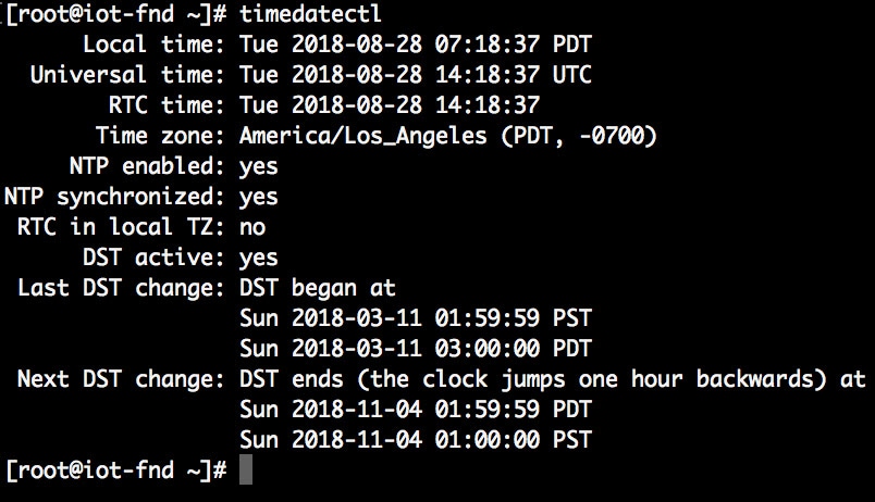
Please refer to the following link for more info on usage of timedatectl command
https://access.redhat.com/documentation/en-us/red_hat_enterprise_linux/7/html/system_administrators_guide/chap-configuring_the_date_and_time
Related Documentation
For information about FND, go to the following:
https://www.cisco.com/c/en/us/support/cloud-systems-management/iot-field-network-director/tsd-products-support-series-home.html
Cisco Fog Director Reference Guide:
http://www.cisco.com/c/en/us/support/cloud-systems-management/fog-director/products-technical-reference-list.html
Cisco IOx Local Manager User Guide
https://www.cisco.com/c/en/us/td/docs/routers/access/800/software/guides/iox/lm/reference-guide/1-6/iox_local_manager_ref_guide.html
For additional information about Cisco IOx, go to the following:
DevNet documentation on IOx. Provides an overview as well as details by scrolling down the left hand side:
https://developer.cisco.com/site/devnet/support/
https://www.cisco.com/c/en/us/support/cloud-systems-management/iox/tsd-products-support-series-home.html
 Feedback