Cisco Connected Grid 4G LTE Module Installation and Configuration Guide
Overview
This document provides an overview of hardware and configuration information for the 4th Generation (4G) Long Term Evolution (LTE) cellular data technology module for the Cisco Connected Grid 1000 Series routers (CGR 1000) running Cisco IOS Software
For the 2G, 3G, or 4G LTE networks that the 4G LTE module can connect to, refer to Table 2.
Refer to Features for a summary of software and platform requirements by 4G LTE model.
 Warning |
Only trained and qualified personnel should be allowed to install, replace, or service this equipment. Statement 1030 |
Kit Contents
Your 4G LTE module kit contains the 4G LTE module shown below. The following table lists the module part numbers for the applicable operating regions. Refer to the information shown in this table when ordering parts.
 Note |
The 4G LTE module for the CGR 1000 Series routers is a field-replaceable unit. |
|
Cisco Part Number |
Description |
||
|---|---|---|---|
|
CGM-4G-LTE-LA-AB |
Multimode LTE SKU for APJC and LATAM wireless networks. Comes with Sierra Wireless MC7430 modem and is compatible with these technologies:
|
||
|
CGM-4G-LTE-GA |
Multimode LTE SKU for global wireless networks. Comes with a Sierra Wireless MC7304 modem and is compatible with these technologies:
|
||
|
CGM-4G-LTE-MNA |
Multimode LTE SKU for North American wireless networks (Verizon, AT&T, Sprint, and Canada). Comes with a Sierra Wireless MC7354 modem and is compatible with these technologies:
Module can only be installed within the CGR 1240. |
||
|
CGM-4G-LTE-MNA-AB |
Multimode LTE SKU for North American wireless networks (Verizon, AT&T, Sprint, and Canada). Comes with a Sierra Wireless MC7354 modem and is compatible with these technologies:
Module can be installed within the CGR 1240 and CGR 1120. |
||
|
CGM-4G-LTE-EA-AB |
Multimode LTE SKU for Americas/EMEA. Comes with a Sierra Wireless MC7455 modem and is compatible with these technologies:
|
||
|
CGM-4G-LTE-LA-AB |
Multimode LTE SKU for Asia Pacific (APAC) and Australia. Comes with a Sierra Wireless MC7430 modem and is compatible with these technologies:
|
||
|
CGM-4G-LTE-EA-900 |
Multimode LTE SKU for USA, Mexico, Canada, and Brazil (ATT/Verizon). Comes with a Sierra Wireless MC7455 modem and is compatible with these technologies:
|
The following table lists the operating regions/carriers and frequency bands for the 4G LTE modules.
|
Cisco Part Number |
Modem |
Operating Region/Carrier |
2G |
3G (Diversity) |
4G (MIMO) |
||||
|---|---|---|---|---|---|---|---|---|---|
|
CGM-4G-LTE-LA-AB |
MC7430 |
APJC/LATAM |
No |
B1, B3, B5, B7, B8, B18, B19, B21, B28, B38, B39, B40, B41 |
|||||
|
CGM-4G-LTE-GA |
MC7304 |
Europe |
Quad GSM |
B1 - UMTS 2100 B2 - UMTS 1900 B5 - UMTS 850 B8 - UMTS 900 |
B1 - LTE 2100 B3 - LTE 1800 B7 - LTE-2600 B8 - LTE 900 B20 - LTE - E800 |
||||
|
CGM-4G-LTE-MNA |
MC7354 |
North AmericaATT/Verizon/ Sprint/Canada |
Quad GSM BC0-CDMA-800 BC1-CDMA -1900 BC10 -CDMA -800 |
B2 - UMTS 1900 B4 - UMTS AWS B5 - UMTS 850 BC0 - CDMA -800 BC1 - CDMA - 1900 BC10 - CDMA -800 |
B2 - LTE 1900 B4 - LTE AWS B5 - LTE 850 B17 - LTE-700 B13 - LTE-700 B25 - PCS 1900 |
||||
|
CGM-4G-LTE-MNA-AB |
MC7354 |
North AmericaATT/Verizon/ Sprint/Canada |
Quad GSM BC0- CDMA -800 BC1- CDMA -1900 BC10 - CDMA -800 |
B2 - UMTS 1900 B4 - UMTS AWS B5 - UMTS 850 BC0 - CDMA -800 BC1- CDMA - 1900 BC10 - CDMA -800 |
B2 - LTE 1900 B4 - LTE AWS B5 - LTE 850 B17 - LTE-700 B13 - LTE-700 B25 - PCS 1900 |
||||
|
CGM-4G-LTE-EA-AB |
MC7455 |
Americas/EMEA |
Not supported |
B1, B2, B3, B4, B5, B8 |
B1, B2, B3, B4, B5, B7, B12, B13, B20, B25, B26, B29, B41
|
||||
|
CGM-4G-LTE-LA-AB |
MC7430 |
APAC |
Not supported |
B1, B5, B6, B8, B9, B19 TD-SCDMA B39 |
B1, B3, B5, B7, B8, B18, B19, B21, B28, B38, B39, B40, B41 |
||||
|
CGM-4G-LTE-EA-900 |
MC7455 |
Americas |
Not supported |
B1, B2, B3, B4, B5
|
B1, B2, B3, B4, B5, B7, B12, B13, B20, B25, B26, B29, B41
|
For system requirements, important notes, limitations, open and resolved bugs, and last-minute documentation updates, see the Release Notes on Cisco.com. For translations of the warnings that appear in this document, see Regulatory Compliance and Safety Information for the Cisco 1000 Series Connected Grid Routers.
When using the online publications, see the documents that match the Cisco system software version running on the 4G LTE wireless module.
Features
Listed below is a summary of key software and hardware features for the 4G LTE module. Please also refer to the data sheet for Cisco Connected Grid 3G and 4G LTE Cellular Modules on Cisco.com.
The Cisco Connected Grid 4G LTE module allows utilities to communicate with substations (transmission and distribution) using 2G, 3G, or 4G wireless technologies. The 4G LTE module provides the following software and wireless features. For a description of hardware features, see Hardware Overview.
Software Features
-
Cisco IOS interface type cellular —The software interface to the cellular modems is similar to the asynchronous serial interface. The cellular interface type distinguishes between the cellular WAN link and other asynchronous interfaces.
-
Sierra Wireless' proprietary Control and Status (CnS) host interface protocol.
-
HDLC Framing support for CnS control messages
. -
PPP protocol and framing support for CDMA control messages.
-
The control endpoint provides the IP address for the direct IP-based cellular interface.
-
Integrated dialer with DDR (Dial-on-Demand Routing) features—Allows dial-up to the cellular network using a CHAT script, which allows flexible configuration of the dial-up. By specifying different commands in the script, the user can connect to the different cellular services (technologies). The 4G LTE module supports line timeouts as part of the dialer functionality.
-
Remote Dial-in Capability—The dial-in feature allows users to remotely initiate data calls over 4G for out-of-band management using the cellular interface's current IP address.
-
Display cellular modem diagnostics parameters—The 4G LTE module can display status, modem parameters, roaming state, cellular account, and so on.
-
Cellular modem firmware upgrade —The 4G LTE module supports upgrade of the modem firmware using the Cisco IOS CLI. See Upgrading the Modem Firmware.
-
Cellular modem account activation and provision utility for CDMA. This utility will allow activating the cellular account using IOS CLI. The alternative over the air methods, such as OTASP will be supported by the cellular modem hardware, which may not require the end user intervention.
-
Virtual Diagnostic Monitoring Port—Allows remote access to the modem diagnostic monitoring port using an IP connection.
-
Dual Subscriber Identity Module (SIM) interface—The 4G LTE module has two SIM card sockets for storing critical subscriber authentication information. The SIM card can be installed in either of the two available sockets accessible on the front panel of the 4G LTE module. Only one slot is active at any given time. The software can detect when a SIM card is inserted or removed, and through the software you can control which SIM is connected to the modem. See Applying a Modem Profile in a SIM Configuration.
Application Interface Features
-
NDIS NIC interface support.
-
Multiple non-multiplexed USB channel support.
-
USB selective suspend to maximize power savings.
-
AT command interface (27.007 standard, plus proprietary extended AT commands).
-
Software Development Kit (SDK) including a Linux API (Application Program Interface).
Phone Book
Supports Release 99 phone book features.
Packet Mode Features
-
Quad-mode UMTS (WCDMA) / HSDPA / EDGE / GPRS operation.
-
GPRS multislot class 12-Supports all coding schemes (CS1-CS4).
-
EDGE multislot class 12-Supports all coding schemes (MCS1-MCS9).
-
UMTS R99 (WCDMA) data rates-384 kbps downlink, 384 kbps uplink.
-
HSDPA data rates:
-
Category 6-3.6 Mbps
-
Category 8-7.2 Mbps
-
Category 10-14.4 Mbps
-
Category 12-1.8 Mbps
-
Category 14-21.1 Mbps
-
-
HSUPA data rates:
-
Category 3-1.45 Mbps uplink respectively.
-
Category 5-2.0 Mbps uplink respectively.
-
Category 6-5.76 Mbps.
-
-
Circuit-switched data bearers-64 kbps (maximum) uplink and downlink.
Connectivity and GSM Features
-
Multiple (up to 16) cellular packet data profiles.
-
Traditional modem COM port support for DUN, CSD, and AT commands (concurrent with NDIS).
-
Suspend / Resume.
-
Sleep mode for minimum idle power draw.
-
SIM application tool kit with proactive SIM commands.
-
Enhanced Operator Name String (EONS).
-
Automatic GPRS attach at power-up.
-
GPRS detach / GPRS detach only.
-
Combined GPRS / IMSI detach; MS-initiated and network-initiated detach.
-
Mobile-originated PDP context activation / deactivation.
-
Supports QoS profile:
-
Release 99 QoS negotiation-Background, Interactive, and Streaming.
-
Release 97-Precedence Class, Reliability Class, Delay Class, Peak Throughput, Mean Throughput.
-
-
Static and Dynamic IP address—The network may assign a fixed IP address or dynamically assign one using DHCP (Dynamic Host Configuration Protocol).
-
PAP and CHAP support.
-
Packet Data Protocol (PDP) context type (IPv4).
-
RFC1144 TCP/IP header compression.
-
Interaction with existing GSM services (MO / MT SMS) while:
-
GPRS is attached, or
-
In a GPRS data session (class B GPRS suspend/resume procedures)
-
-
Support for EAP-SIM authentication and PC / SC. EAP-SIM is available through:
-
The API
-
AT commands
-
The PC / SC interface
-
Network Selection
-
Network selection procedures described in 3G 22.011, R5 (June 2005).
-
Network selection procedures described in 3G 23.122, R5 (June 2005).
-
RRC connection reject message to redirect from a 3G system to a 2G system, according to 25.331, R5 (June 2004).
-
Network selection procedures described in 3G 43.022, R4.
-
A CPHS Customer Service Profile-like feature (PLMN Mode bit) on a USIM / SIM that hides network selection related menus.
-
Initial HPLMN scan at two minutes after power on.
-
An HPLMN rescan irrespective of the serving MCC.
-
Disabling of non-North American 2G and 3G frequency bands when served by a North American 2G/3G system.
-
Equivalent PLMN.
-
Network selection generally within 30 seconds of power up.
-
Enhanced network selection (ENS).
RF Features
For details on 2G, 3G, and 4G bands, see Table 2.
Hardware Overview
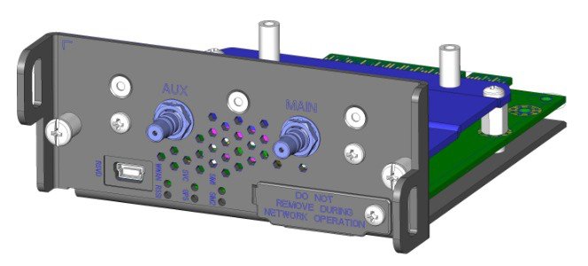
The 4G LTE module is a wireless module with a mini-card cellular modem (PCI-e mini-card form factor). The module connects to the host router board of the CGR 1000 Series routers.
Front Panel
The front panel of the 4G LTE module has the following components:
-
Auxiliary port—QMA connector for the RX diversity and MIMO antenna.
-
QMA connector for antenna—transmits and receives RF.
-
Mini-USB port—Can be used as a diagnostic port.
-
LEDs:
-
Wireless WAN (WWAN)
-
Received Signal Strength Indication (RSSI)
-
Service (SVC)
-
LTE
-
SIM0 and SIM1
-
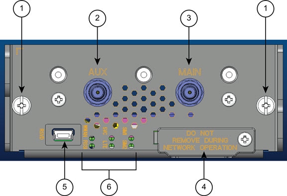
The following figure shows the front panel components of the 4G LTE module.
|
1 |
Captive screws (2) |
2 |
Auxiliary port—QMA connector for RX diversity and/or multiple-input and multiple-output (MIMO) antenna. |
|
3 |
Main port—QMA connector for antenna—transmits and receives RF. |
4 |
SIM card slots |
|
5 |
RSVD—Mini-USB port (can be diagnostic port). |
6 |
LEDs—WWAN, RSSI, SVC, LTE, SIM0, and SIM1. |
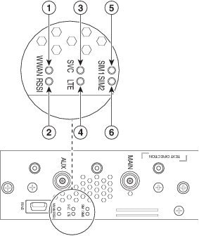
Ports and LEDs
The following figure shows the LEDs of the 4G LTE module.
|
1 |
WWAN LED |
2 |
RSSI LED |
|
3 |
SVC LED |
4 |
LTE LED |
|
5 |
SIM0 LED |
6 |
SIM1 LED |
The following table lists the ports and the LED indicators and describes their behavior. The LEDs provide a visual indication of the available services.
|
Port or LED Name |
Color |
Description |
|---|---|---|
|
WWAN |
Green |
WWAN LED indicates the modem status:
|
|
RSSI |
Green |
RSSI LED indicates the level of signal strength:
|
|
SVC |
Green |
Service LED indicates the following:
|
|
LTE |
Green |
LTE LED indicates the status of the LTE service:
|
|
SIM0, SIM1 |
Bi-color green/amber |
Hardware controls the SIM0 and SIM1 LEDs under normal operation. Software controls SIM insertion/removal and the software setting of the SIM Socket Select bit.
|
Supported Cisco Antennas
The antenna is connected to the QMA, panel-mount, 50-ohm connector located on the faceplate of the module. Internally to the CGM module, the modem mini-card antenna connector is a U.FL, 50-ohm, with a short 50-ohm coaxial cable to the QMA connector.
Note |
The antennas have either N or TNC connectors (not QMA connectors). This means that an adapter or cable is required. |
For more information about antennas, including installation procedures, see Connected Grid Antennas Installation Guide .
There are several antenna options for the available combinations of cable and antennas. System integrators would need to consider cellular link margins at the local site prior to deploying long cables.
The following tables list the Cisco antennas that are supported for use with the 4G LTE module and the Cisco 1120 and Cisco 1240 Connected Grid Routers.
|
Case Description |
Indoor Cable |
Lightning Arrestor |
Outdoor Cable |
Antenna |
|---|---|---|---|---|
|
Case 1: 4G LTE Module, 10’, 15’ or 20’ cable through conduit or building entry panel passthrough, Stick Omni or Directional Flat Panel antenna, 2 QMA(f) on faceplate |
RA-QMA(m) to N(m), LMR-240-DB, 10’, qty 2
|
None |
Same cable as indoor cable, that is, a single cable runs from inside to outside, through conduit. |
4G omni stick, N(f), qty 2
|
|
RA-QMA(m) to N(m), LMR-240-DB, 15’, qty 2
|
4G directional panel, dual polarized/MIMO, 698-960 MHz, 1710-2700 MHz, qty 1
|
|||
|
RA-QMA(m) to N(m), LMR-240-DB, 20’, qty 2
|
||||
|
Case 2: 4G LTE Module, Indoor Cable, Lightning Arrestor, Outdoor Cable, Stick Omni or Directional Flat Panel antenna, 2 QMA(f) on faceplate |
RA-QMA(m) to N(m), LMR-240-DB, 10’, qty 2
|
Lightning Arrestor, N(f)-N(f), qty 2
|
RA-N(m) to N(m), LMR-400-DB, 20’, qty 2
|
4G omni stick, N(f), qty 2
|
|
RA-N(m)-N(m), LMR-600-DB, 30’,qty 2
RA-N(m) to N(m), LMR-400-DB, 5’, qty 2
N(m)-N(m), LMR-400-DB, 5’,qty 2
|
|
(f) denotes female connector
(m) denotes male connector
|
Case Description |
Internal Cable |
Adapter or Lightning Arrestor |
Outdoor Cable |
Antenna |
|---|---|---|---|---|
|
Case 1: Integrated Antenna, 4G LTE Connected Grid Module, 2 QMA(f) on faceplate |
RA-QMA(m) to RA-MCX(m), LMR-100, 10.5”, qty 2 |
None |
None |
4G, 698-960 MHz, 1710-2700 MHz, ISM 915 MHz Monopole Antenna, Chassis Mounted, Omni-directional, qty 2
|
|
Case 2: External Antenna, 4G LTE Connected Grid Module, 2 QMA(f) on faceplate |
RA-QMA(m) to RA-MCX(m), LMR-100, 10.5”, qty 2 |
Bulkhead Adapter, MCX(f) receptacle – N(f), qty 2
and Lightning Arrestor, DC Pass, N(m)-N(f), qty 2
|
RA-N(m)-N(m), LMR-400-DB, 20’, qty 2
N(m)-N(m), LMR-400-DB, 5’,qty 2
|
4G omni stick, N(f), qty 2
|
|
RA-N(m)-N(m), LMR-600-DB, 30’, qty 2
|
4G directional panel, dual polarized/MIMO, 698-960 MHz, 1710-2700 MHz, qty 1
|
Supported Cisco Cables
The following table lists insertion loss information and operating frequency levels for the Ultra-Low-Loss (ULL) LMR cables, and LMR 400 cables available from Cisco for use with the 4G LTE module.
You can use LMR-240-DB or LMR-400-DB cables to adapt the modem external antenna connection. Refer to Supported Cisco Antennas for cable compatibility with Cisco Connected Grid routers, modules, and antennas.
|
Cisco Product Number |
Cable Length |
Maximum Insertion Loss |
Frequency (MHz) |
|---|---|---|---|
|
CAB-L240-10-Q-N |
10 ft (3.1 m) |
1.6 dB max. at 2700 MHz |
700 to 2700 MHz |
|
CAB-L240-15-Q-N |
15 ft (4.6 m) |
2.3 dB max. at 2700 MHz |
700 to 2700 MHz |
|
CAB-L240-20-Q-N |
20 ft (6.1 m) |
3.1 dB max. at 2700 MHz |
700 to 2700 MHz |
|
CAB-L400-5-N-NS |
5 ft (1.5m) |
0.5 dB max at 2700 MHz |
700 to 2700 MHz |
|
CAB-L400-5-N-N |
5 ft (1.5m) |
0.5 dB max. at 2700 MHz |
700 to 2700 MHz |
|
CAB-L400-20-N-N |
20 ft (6.1m) |
1.7 dB max. at 2700 MHz |
700 to 2700 MHz |
|
CAB-L600-30-N-N |
30 ft (9.1m) |
1.1 dB max. at 2700 MHz |
700 to 2700 MHz |
Interfaces
The module includes the following physical interfaces to the host:
-
Power—Supplied to the module by the host.
-
Wireless disable—As described in the PCI-Express Mini Card specification.
-
LED output—As described in the PCI-Express Mini Card specification.
-
Antenna—QMA (f) RF connector for the Rx/Tx path.
-
USIM—Supported through the interface connector.
-
USB—Only communication interface to the host for data, control, and status information.
Radio Frequency Interface
The Radio Frequency (RF) interface consists of two QMA connectors on the faceplate labeled MAIN and AUX . The main antenna is mandatory; it both transmits and receives RF. The second AUX QMA connector is for RX Diversity and/or MIMO.
Environmental Specifications
The following table lists the environmental specifications for the 4G LTE module.
|
Environmental—Operational |
Specifications |
|---|---|
|
Temperature long term (external ambient) |
- 40°F to 140°F (-40°C to 60°C) |
|
Temperature short term up to 16 hours (external ambient) |
- 40°F to 185°F (-40°C to 85°C) |
|
Altitude |
Up to 1500 meters |
|
Humidity |
RH95% non condensed |
|
Vibration |
1.0 g from 1.0 to 150 Hz |
|
Shock |
30 G half sine 6 ms and 11 ms |
|
Seismic |
GR63-Core, Zone 4 |
Power Specifications
The 4G LTE module has a 12V power rail and 3.3V stand-by power provided by the host system. It has two 3.3V DC-DC converters on the 12V power rail: one for the module and the other for the modem. You can configure a power margin for the converters with CLI commands.
The modem on the 4G LTE module is powered by the 12v to 3.3v DC-DC converter with 3 Amp maximum current output. The enable pin is driven by a general-purpose input/output (GPIO) and controlled by software. The input is the 12V rail from the host. The output is a regulated 3.3V supply for the wireless modem. It must be able to supply current at an average of 0.8A with spikes up to 2.5A. The duty cycle of the absolute worst case load (during some periods of GSM transmit) is 2.5A @ 25% of the time and 0.2A @ 75%.
Note |
Power cables are self-shielded; no additional shielding is required. |
|
Power Source |
Description |
|---|---|
|
12V power rail |
Max 1A (based on current draw from 2 DC-DC converters below) |
|
3.3V modem |
Peak current 3.75A, average power: 3W (based on average current of ~0.8A) |
|
3.3V module |
Peak current 500mA typical: 200mA (for LEDs and integrated circuitry) |
|
3.3V standby |
Peak current 500mA (for temperature sensor) |
Modem
The MC73xx series modems support a PCI-e connection as well as USB 2.0. The host router communicates to the modem module and manages traffic via USB. The modem provides these features:
-
Ruggedized for industrial extended temperature ranges
-
USB 2.0 high speed interface
-
Three GPIOs for OEM use
-
Two 4G antenna for MIMO and Diversity
-
ACT2 version 1.5 anti counterfeiting device
The MC73xx PCI Express mini-card modem provides EDGE, GPRS, GSM, WCDMA, HSDPA, HSUPA, HSPA+, and LTE wireless radio connectivity technologies over the frequency bands listed in the following table. .
|
Technology |
Frequency Bands, CGM-4G-LTE-GA |
Frequency Bands, CGM-LTE-MNA, CGM-4G-LTE-MNA-AB |
Maximum Data Rates |
|---|---|---|---|
|
LTE (MIMO Support) |
|
|
Category 3
|
|
UMTS(WCDMA)HSDPAHSUPAHSPA+DC-HSPA+(Diversity support) |
|
|
HSPA+ rates
|
|
GSM EDGE GPRS |
|
|
EDGE throughput up to 236 kbps |
|
CDMA EVDO Release 0 EVDO Release A (Diversity support) |
|
|
|
SIM Interface
Note |
We recommend you use an industrialized and ruggedized SIM card that can operate in a-40 degree C to + 105 degree C environment for best performance. |
The 4G LTE module has two SIM card sockets for storing critical subscriber authentication information. You can install the SIM card in either of the two available sockets accessible on the front panel. Only one slot is active at any given time—if both slots SIM0 and SIM1 are occupied by a card, then the system activates SIM0. This behavior cannot be reconfigured.
-
The SIM card stores critical subscriber authentication information.
-
The two SIM cards are powered by the modem and operate at 5 MHz.
-
The SIM card is a 3.3 V device, and it has 2.8 V power applied to its power pin.
Through the software you can control which SIM is connected to the modem. Only one SIM can be connected to the modem at any time. The SIM switching circuit also provides the option of disconnecting both SIMs from the modem. The 4G Debug and SIM Control register controls the SIM connections.
By setting the SIM Socket Enable and the SIM Socket Select bit through Cisco IOS commands, you can control the signal and power connections from the modem to the SIM card.
The following table shows the options used to connect to SIM0 and SIM1 cards:
|
SIM Socket Enable |
SIM Socket Select |
State |
|---|---|---|
|
0 |
— |
No SIM connected |
|
1 |
0 |
SIM0 connected |
|
1 |
1 |
SIM1 connected |
For information on installing and removing the SIM card, see Installing and Removing the SIM Card.
For SIM configuration, see Configuring a SIM for Data Calls.
Voltage Monitoring State Machine
A state machine in the 4G LTE module monitors the VCC supply and the voltage conditions that trigger state changes.
Temperature Monitoring State Machine
The state machine in the 4G LTE module monitors the embedded module temperature.
Data Rates
The following table shows the theoretical rates for each listed technology. The actual throughput rates depend on many factors.
|
Technology |
EDGE |
UMTS |
HSDPA |
LTE |
|---|---|---|---|---|
|
Maximum Downlink Speed |
236 kbps Typical data throughput 100-300kbps with bursts over 200 kbps |
Up to 1.92 Mbps, Current networks and chipsets support 384 kbps |
Up to 14.4 Mbps Current networks and chipsets support up to 1.4 Mbps |
100Mbps (20MHz band) 50Mbps (10MHz band) |
|
Maximum Uplink Speed |
236 kbps Typical data throughput 100-300 kbps |
Up to 384 Kbps |
Up to 384 Kbps |
50Mbps (20MHz band) 25Mbps (10MHz band) |
Memory Specifications
The memory specifications of the module are listed in the following table.
|
Memory Type |
Minimum |
Maximum |
|---|---|---|
|
DDR2 SDRAM |
1Gb (128 MB) |
NA (1Gb is sufficient for the Linux SDK design and modem firmware upgrade) |
|
DDR2 SDRAM for fixed platforms |
512 MB (384 MB for IOS and 128 MB for Linux) |
— |
Module Power States
The module has the following power states:
-
Disconnected—There is no power to the module. The host power source is disconnected from the module and all voltages associated with the module are at 0 V.
The CGR 1000 Series router controls the power to the module, therefore the host can stay powered on and cut the power in order to put the module into the disconnected state.
-
Off—There is power to the module, but the module is powered off. The module begins a shutdown sequence and powers off if it has been in a powered-on state for more than 10.5 seconds and the host device drives the W_Disable# signal low for:
-
Normal (default state)—Module is active. Receive, Transmit, Sleep, and Shutdown modes are possible. In this state:
-
The module is fully powered
-
The module is capable of placing/receiving calls or establishing data connections on the wireless network
-
The USB interface is fully active
-
Note |
The module defaults to the Normal state when VCC is first applied in the absence of W_Disable# control. |
-
Low power (airplane mode)—The module is active, but RF is disabled. In this state, RF (both Rx and Tx) is disabled on the module, but the USB interface is still active.
Note |
The module goes from normal state into low-power state to suspend RF activity. This occurs when the module’s supply voltage exceeds either the high or low limits. The module returns to normal mode to resume RF activity. It occurs when the module’s supply voltage returns from critical to normal limits. |
Installing and Removing the SIM Card
For more information on the SIM interface, see SIM Interface.
Preventing Electrostatic Discharge Damage
Electrostatic Discharge (ESD) damage can occur when electronic cards or components are handled improperly, which can result in complete or intermittent failures.
To prevent ESD damage:
-
Always use an ESD wrist or ankle strap and ensure that it makes good skin contact.
-
Connect the equipment end of the strap to an unfinished chassis surface.
-
Place a removed compact SIM card on an antistatic surface or in a static shielding bag. If the card will be returned to the factory, immediately place it in a static shielding bag.
-
Avoid contact between the card and clothing. The wrist strap protects the card from ESD voltages on the body only; ESD voltages on clothing can still cause damage.
-
Do not remove the wrist strap until the installation is complete.
Warning |
Only trained and qualified personnel should be allowed to install, replace, or service this equipment. Statement 1030 |
 Caution |
For safety, periodically check the resistance value of the antistatic strap. The measurement should be between 1 and 10 megohms (Mohms). |
Installing the SIM Card
To install the SIM card:
Procedure
| Step 1 |
Using a Phillips-head screwdriver, loosen the screw that secures the SIM slot cover in place. Rotate the cover downward so it exposes the SIM slot. |
| Step 2 |
Insert the SIM card with the key (notch) positioned on the right-hand side. The SIM card will come in contact with the metal contacts in the socket. 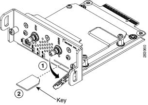 |
| Step 3 |
Firmly insert the card until it clicks into place. |
| Step 4 |
Rotate the cover back in place and secure it by tightening the screw. |
What to do next
You must reload the system after installing or changing the SIM card.
Removing the SIM Card
To remove the SIM card:
Procedure
| Step 1 |
Open the cover and press the card to eject it. |
| Step 2 |
Remove the card and replace the cover. |
Installing and Removing the 4G LTE Module
Some Cisco Connected Grid 4G LTE modules are installed in the host router at the factory.
Installing the 4G LTE Module
Caution |
The 4G LTE module can only be installed into slots 3 or 6 of Cisco 1240 Connected Grid Router. |
Caution |
The 4G LTE module can only be installed into slots 3 or 4 of Cisco 1120 Connected Grid Router. |
Caution |
The module cannot be hot swapped. To install the module, you must first power down the host router. |
Caution |
CGM-4G-LTE-MNA cannot be installed in the CGR 1120 chassis. CGM-4G-LTE-MNA-AB can be installed in both platforms. See Feature History. |
To install the module into the router:
Before you begin
Before you install the 4G LTE module into the host router, read the instructions about installing and removing modules in the Hardware Installation Guide of your router.
Before installing the module, verify that you have met the following guidelines:
-
Clearance to the I/O-side view is such that the LEDs can be easily read.
-
Cabling is away from sources of electrical noise, such as radios, power lines, and fluorescent lighting fixtures. Make sure that the cabling is away from other devices that might damage the cables.
-
Airflow around the switch module and through the vents is unrestricted.
-
Temperature around the unit does not exceed 140°F (60° C). If the switch module is installed in a closed or multi-rack assembly, the temperature around it might be higher than normal room temperature.
-
Relative humidity around the switch module does not exceed 95 percent (non-condensing).
-
Altitude at the installation site is not higher than 4921 feet (1500 meters).
-
For 10/100 and 10/100/1000 fixed ports, cable lengths from the switch module to connected devices are not longer than 328 feet (100 meters).
This section includes the basic installation warning statements. Translations of these warning statements appear in the Regulatory Compliance and Safety Information for Cisco Connected Grid Router 1000 Series Routers document.
Warning |
This unit is intended for installation in restricted access areas. A restricted access area can be accessed only through the use of a special tool, lock and key, or other means of security. Statement 1017 |
Warning |
Only trained and qualified personnel should be allowed to install, replace, or service this equipment. Statement 1030 |
Warning |
To prevent the system from overheating, do not operate it in an area that exceeds the maximum recommended ambient temperature of: 140°F (60°C) Statement 1047 |
Warning |
This equipment is intended to be grounded to comply with emission and immunity requirements. Ensure that the switch functional ground lug is connected to earth ground during normal use. Statement 1064 |
Warning |
To prevent airflow restriction, allow clearance around the ventilation openings to be at least: 1.75 in. (4.4 cm) Statement 1076 |
Procedure
| Step 1 |
Insert the module into the slot. (CGR 1120 and CGR 1240 shown.) 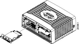 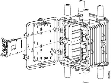 |
| Step 2 |
Using a screwdriver, secure the two captive screws into place. Tighten to 5 to 8 pound-force inches (lbf-in.). |
Removing the Module
Before you begin
Caution |
The module cannot be hot swapped. To install the module, you must first power down the host router. |
Before you remove the 4G LTE module from the host router, power down the router as described in the Hardware Installation Guide of your router.
Procedure
| Step 1 |
Using a screwdriver, loosen the two captive screws on the 4G LTE module. |
| Step 2 |
Gently pull the module out of the slot. |
Regulatory and Compliance Information
For regulatory compliance and safety information for the module, refer to Regulatory Compliance and Safety Information for the Cisco 1000 Series Connected Grid Routers.
LTE Overview
The Long Term Evolution (LTE) standard for wireless data communication is developed by the 3GPP (Third Generation Partnership Project). LTE was introduced in 3GPP Release 8, with enhancements in subsequent 3GPP Releases.
4G LTE is the next stage beyond 3G in the 3GPP evolution of wireless communication technologies. LTE transitions from the combined circuit and packet switching network used in the 3G architecture to an all-IP flat architecture. The LTE architecture involves the following major components:
-
Evolved Universal Terrestrial Access Network (E-UTRAN)—The LTE access network is a network of evolved NodeB (eNB) base stations with no centralized intelligent controller. This distributed network of intelligent base stations reduces the time required for handovers.
-
Evolved Packet Core (EPC)—User Equipment (UE) (for example, the Connected Grid 4G LTE module) connects to the EPC over E-UTRAN. The EPC connects to external networks and is completely IP-based. As in the access network, the EPC has a flat architecture so that fewer nodes handle traffic, avoiding protocol conversion.
LTE uses Orthogonal Frequency Division Multiplexing (OFDM) and Multiple-Input Multiple-Output (MIMO) functionality in the radio link at the physical layer to provide spectral efficiency and flexibility, high peak data rates, and low latency. The LTE standards specify a theoretical downlink peak data rate of up to 300 Mbps, uplink peak data rate of 75 Mbps, and user plane latency of less than 5 ms.
For more information about LTE and 3GPP mobile broadband standards, go to http://www.3gpp.org/.
Configuring the 4G LTE Module
The module is configured using the system software.
Prerequisites
To configure the 4G LTE module, you must meet the following requirements:
-
Have 4G LTE network coverage where your router will be physically located. For a complete list of supported carriers, see the product data sheet.
-
Subscribe to a service plan with a wireless service provider and obtain a SIM card.
-
Contact your ISP and get your access point name (APN).
-
Install the SIM card before configuring the 4G LTE module. For instructions on how to install the SIM card, see the section, Installing the SIM Card.
Guidelines and Limitations
The following guidelines and limitations apply to configuring the 4G LTE module:
-
Global Positioning System (GPS) and Short Message Service (SMS) are not supported.
-
Data connection can be originated only by the module.
-
Throughput: Due to the shared nature of wireless communications, the experienced throughput varies depending on the number of active users or congestion in a given network.
-
Cellular networks have higher latency compared to wired networks. Latency rates depend on the technology and carrier. Latency may be higher because of network congestion.
-
Any restrictions that are a part of the terms of service from your carrier.
-
The 4G LTE module can be plugged into slots 3 or 6 of Cisco 1240 Connected Grid Router. Therefore, the interface names used to configure the module can be 3/1 or 6/1.
-
The 4G LTE module can be plugged into slots 3 or 4 of Cisco 1120 Connected Grid Router. Therefore, the interface names used to configure the module can be 3/1 or 4/1.
-
CGM-4G-LTE-MNA is not compatible with CGR 1120, CGM-4G-LTE-MNA-AB is compatible with both platforms.
Note |
In command syntax, the LTE cellular interface is shown as cellular slot/subslot , where slot refers to the CGR slot where the module resides, and subslot is always 1. |
Note |
In the following examples, the interface name, including the slot number, is used as an example. Your configuration will vary depending on the slot in which you have installed your 4G LTE module. |
Creating, Modifying, or Deleting Modem Data Profiles
The modem data profile contains the data service parameters used to set up a data call. You can create up to 16 data profiles on the Cisco 4G LTE module. The default profile is Profile 1.
Before you begin
Contact your ISP and get your access point name (APN).
Procedure
| Step 1 |
To create an LTE modem data profile, enter the following command in privileged EXEC mode: cellular slot/subslot lte profile create profile-number apn
|
| Step 2 |
(Optional) To delete an LTE profile, enter the following command in privileged EXEC mode: cellular slot/subslot lte profile delete profile-number |
Example
4G-CGR1K# cellular 4/1 lte profile create 1 Broadband
Changing Modem Technology Setting
You can restrict or allow the type of LTE technology (auto, GSM, UMTS, or LTE) the modem can use.
Before you begin
Procedure
| Step 1 |
Enter the following Cisco IOS command in privileged EXEC mode: cellular slot/subslot lte technology technology
|
| Step 2 |
(Optional) To display the LTE technology, use the show cellular slot/subslot radio command. |
Example
4G-CGR1K# cellular 4/1 lte technology auto
4G-CGR1K# show cellular 4/1 radio
Radio power mode = ON
Channel Number = 0
Current Band = GSM 900 Extended
Current RSSI = -57 dBm
Current ECIO = -127 dBm
Radio Access Technology(RAT) Preference = AUTO
Radio Access Technology(RAT) Selected = EDGE
Configuring a SIM for Data Calls
The 4G LTE module has two SIM card sockets for storing critical subscriber authentication information. The SIM card can be installed in either of the two available sockets accessible on the front panel of the 4G LTE module. Only one slot is active at any given time. The software can detect when a SIM card is inserted or removed, and through the software you can control which SIM is connected to the modem. (See Applying a Modem Profile in a SIM Configuration.)
SIM cards can be locked and unlocked:
-
Service providers usually provide SIM cards in an unlocked state. If the SIM is unlocked, you can insert it into the 4G LTE module and use it without a Personal Identification Number (PIN).
-
Service providers can also initially lock the SIM with a PIN code (4 to 8 digits long) that they define. Contact your service provider for the PIN code.
The SIM-Lock feature allows you to lock or unlock a SIM with a PIN code so that it is used only in an authorized device. Perform the SIM lock and unlock procedures using the Cisco IOS CLI through a console or Telnet/SSH to the router.
After the SIM is locked, it cannot initiate a call unless authentication is done using the same PIN. During router startup configuration, Cisco IOS performs SIM authentication automatically through configuration of the PIN. After the Cisco IOS configuration is in place, the router can initiate an LTE connection. The router uses the configured PIN to authenticate prior to the LTE connection. If the Cisco IOS PIN configuration is missing or if the PIN is incorrect, the SIM authentication will fail and the connection will not be initiated.
If the locked SIM is moved to a different router or to another device, or if the module in which the locked SIM resides is moved to a different slot in the same router, you need to change the router configuration. The configuration is associated with the cellular controller that is specific to a CGR 1000 Series router module slot number. This ensures that the SIM card will not be used in any unauthorized device, or, if there are multiple 4G LTE modules in a single CGR 1000 Series router, that the appropriate PIN is applied to each 4G LTE module/SIM. You must define an authentication command (with the same PIN used to lock the SIM) on the new device or on the new cellular controller slot to successfully initiate the LTE connection.
Locking and Unlocking a SIM Card Using a PIN Code
Enter the following command in privileged EXEC mode to lock or unlock a SIM card given by your service provider:
Before you begin
Caution |
The SIM card gets blocked if the wrong PIN is entered three consecutive times. Make sure you enter the correct PIN the SIM is configured with. If your SIM card gets blocked, contact your service provider for a PIN Unlock Key (PUK) code. Using the PUK code, you can unblock the SIM card. |
Procedure
|
cellular slot/subslot lte sim { lock | unlock } pin pin is a code (4 to 8 digits long) provided by your carrier to lock or unlock the SIM card. |
Example
4G-CGR1K# cellular 4/1 lte sim lock 1111
Changing the PIN Code
Enter the following command in privileged EXEC mode to change the PIN code of a SIM.
Before you begin
SIM should be in locked state when the PIN is being changed.
Procedure
|
cellular slot/subslot lte sim change-pin pin new-pin |
Example
4G-CGR1K# cellular 4/1 lte sim change-pin 1111 1234
Verifying the Security Information of a Modem
To verify the security information of a modem, including the SIM lock status, enter the following command:
Procedure
|
show cellular slot/subslot security |
Example
4G-CGR1K# show cellular 4/1 securityConfiguring Automatic Authentication for a Locked SIM
An unencrypted PIN can be configured to activate the Card Holder Verification (CHV1) code that authenticates a modem. Follow this procedure when using an unencrypted Level 0 PIN to configure CHV1. For instructions on how to configure CHV1 using an encrypted Level 7 PIN, see Configuring an Encrypted PIN for a SIM.
Before you begin
A SIM should be locked for SIM authentication to work. To verify SIM status, use the show cellular slot/subslot security command.
Procedure
| Step 1 |
Enter global configuration mode: configure terminal |
||
| Step 2 |
Specify authentication of the SIM CHV1 code by using an unencrypted (0) keyword and PIN. lte sim authenticate 0 pin slot { 0 | 1 } This PIN is sent to the modem for authentication with each subsequent LTE connection. If authentication passes based on the configured PIN, the data call is allowed. If authentication fails, the modem does not initiate the data call.
|
Example
4G-CGR1K# configure terminal
4G-CGR1K(config)# controller cellular 4/1
4G-CGR1K(config-controller)# lte sim authenticate 0 1111 slot 0
Configuring an Encrypted PIN for a SIM
To configure an encrypted PIN, you must first obtain the scrambled value of the PIN. To get the scrambled Level 7 PIN and to configure the SIM CHV1 code for verification using this encrypted PIN, follow this procedure.
Note |
When obtaining the encrypted PIN for a SIM, you create a username and password by configuring password encryption, defining the username and associated password, copying the resulting scrambled password, and using this scrambled password in the SIM authentication command. After the scrambled PIN has been obtained and used in SIM authentication, you can delete the username created from the Cisco IOS configuration. |
Before you begin
A SIM should be locked for SIM authentication to work. To verify SIM status, use the show cellular slot/subslot security command.
Procedure
| Step 1 |
Enter global configuration mode: configure terminal |
| Step 2 |
Enable password encryption: service password-encryption |
| Step 3 |
Create a username and password: username name privilege 0 password pin
|
| Step 4 |
Show the username configuration line with the encrypted level 7 PIN for the username created in step 3. Copy the scrambled password. do show run | i name |
| Step 5 |
Enter cellular controller configuration mode. controller cellular slot/subslot |
| Step 6 |
Specify authentication of the SIM CHV1 code by using the encrypted keyword 7 and the scrambled PIN from step 4. lte sim authenticate { 0 | 7 } pin slot { 0 | 1 } The PIN is sent to the modem for authentication with each subsequent LTE connection. If authentication passes based on the configured PIN, the data call is allowed. If authentication fails, the modem does not initiate the data call. |
| Step 7 |
(Optional) Exit cellular controller configuration mode. exit |
| Step 8 |
(Optional) Remove the username and password created in step 3. no username name |
| Step 9 |
(Optional) Disable password encryption: no service password-encryption |
Example
4G-CGR1K# configure terminal
4G-CGR1K(config)# service password-encryption
4G-CGR1K(config)# username SIM privilege 0 password 1111
4G-CGR1K(config)# do show run | i SIM
4G-CGR1K(config)# controller cellular 4/1
4G-CGR1K(config-controller)# lte sim authenticate 7 055A575E70 slot 0
4G-CGR1K(config-controller)# exit
4G-CGR1K(config)# no username SIM
4G-CGR1K(config)# no service password-encryption
Applying a Modem Profile in a SIM Configuration
Follow this procedure to specify the profile used by the modem to attach to the LTE network and send and receive data. To create profiles, see step 1 in Configuring the Cellular Interface.
Before you begin
Review the information about SIM cards in Configuring a SIM for Data Calls.
Procedure
| Step 1 |
Enter global configuration mode: configure terminal |
| Step 2 |
Enter cellular controller configuration mode: controller cellular slot/subslot |
| Step 3 |
Apply the configured data profile number to the SIM. lte sim data-profile profile-number attach-profile attach-profile-number |
Example
4G-CGR1K# configure terminal
4G-CGR1K(config)# controller cellular 4/1
4G-CGR1K(config-controller)# lte sim data-profile 1 attach-profile 1
Configuring a Dual SIM
The Dual SIM feature provides a failover mechanism in case the active SIM loses connectivity to the network. Follow this procedure to configure a dual SIM.
Before you begin
Review these guidelines for configuring a dual SIM:
-
By default, SIM slot 0 is the primary slot, and slot 1 is the backup.
-
To change the primary SIM slot, use the lte sim primary command in the cellular controller configuration mode.
-
Assign profiles for each SIM using the lte sim data-profile command.
-
Use the following commands to display SIM information:
-
show cellular slot/subslot profile all —Display an active profile on a SIM
-
show cellular slot/subslot security —Display the status of a dual SIM
-
show controller cellular slot/subslot —Display the status of a dual SIM
-
Procedure
| Step 1 |
Enter global configuration mode: configure terminal |
| Step 2 |
Enter the cellular controller configuration mode: controller cellular slot/subslot |
| Step 3 |
(Optional) Enter either slot number 0 or 1 of the primary SIM. lte sim primary slot |
| Step 4 |
(Optional) Specify the maximum number of failover retries from 1 to 65535. The default value is 10. lte sim max-retry number |
| Step 5 |
(Optional) Specify a failover timeout value between 1 and 7 minutes before a switchover occurs. By default, the failover time period is 2 minutes before the primary SIM switches over to the secondary SIM if service becomes unavailable. lte failovertimer timeout-period |
| Step 6 |
Apply the configured profile number to the SIM. lte sim data-profile profile-number attach-profile attach-profile-number |
Example
4G-CGR1K# configure terminal
4G-CGR1K(config)# controller cellular 4/1
4G-CGR1K(config-controller)# lte sim primary 1
4G-CGR1K(config-controller)# lte sim max-retry 20
4G-CGR1K(config-controller)# lte failovertimer 6
4G-CGR1K(config-controller)# lte sim data-profile 1 attach-profile 1
Configuring the Cellular Interface
Procedure
| Step 1 |
Enter global configuration mode: configure terminal |
| Step 2 |
Specify the cellular interface: interface cellular slot/subslot |
| Step 3 |
Specify that the IP address for the interface is dynamically obtained: ip address negotiated |
| Step 4 |
Specify Serial Line Internet Protocol (SLIP) encapsulation for an interface configured for dedicated asynchronous mode or dial-on-demand routing (DDR). This is the default for asynchronous interfaces. encapsulation slip |
| Step 5 |
Set the length of time over which load averages are computed to a shorter length of time (30 seconds): load-interval 30 A burst in traffic that would not trigger a dial backup for an interface configured with the default five-minute interval might trigger a dial backup for this interface, which is set for the shorter 30-second interval. |
| Step 6 |
Enable dial on demand (DDR) routing and specify that a chat script will be used for dialing out. dialer in-band |
| Step 7 |
Set the duration of idle time before the line is disconnected to an indefinite timeout period: dialer idle-timeout 0 This command avoids disconnection of SLIP in the event of no traffic. |
| Step 8 |
Specify the number or string to dial: dialer string string |
| Step 9 |
Specify the number of the dialer access group to which the specific interface belongs: dialer-group group-number |
| Step 10 |
Disable a prior peer IP address pooling configuration on the interface: no peer default ip address |
| Step 11 |
Configure interactive mode on the asynchronous interface: async mode interactive |
| Step 12 |
Enable the router to pass routing updates to other routers through the interface: routing dynamic |
| Step 13 |
Enter global configuration mode: exit |
| Step 14 |
Specify line configuration mode: line slot/subslot |
| Step 15 |
Specify a default modem chat script: script dialer regular-expression |
| Step 16 |
Configure the line for both incoming and outgoing calls: modem inout |
| Step 17 |
Turn off the EXEC process for the line: no exec |
| Step 18 |
Configure the line to accept incoming connections: transport input all |
| Step 19 |
Specify that the line can use all protocols for outgoing connections: transport output all |
| Step 20 |
Enter global configuration mode: exit
|
| Step 21 |
Define the default route to be through the cellular interface: ip route ip-address address-mask cellular slot/subslot In this case all IP packets are routed through the cellular interface. |
| Step 22 |
Create a dialer list for traffic of interest and permit access to an entire protocol: dialer-list 1 protocol ip permit |
| Step 23 |
Create a chat script using the chat-script command: chat-script script-name ”” “ AT!CALL ” TIMEOUT timeout-value “ OK ” The chat-script defines the ATDT commands when the dialer is initiated. |
Example
4G-CGR1K# configure terminal
4G-CGR1K(config)# interface cellular 4/1
4G-CGR1K(config-if)# ip address negotiated
4G-CGR1K(config-if)# encapsulation slip
4G-CGR1K(config-if)# load-interval 30
4G-CGR1K(config-if)# dialer in-band
4G-CGR1K(config-if)# dialer idle-timeout 0
4G-CGR1K(config-if)# dialer string lte
4G-CGR1K(config-if)# dialer-group 1
4G-CGR1K(config-if)# no peer default ip address
4G-CGR1K(config-if)# async mode interactive
4G-CGR1K(config-if)# routing dynamic
4G-CGR1K(config-if)# exit
4G-CGR1K# line 4/1
4G-CGR1K(config-line)# script dialer lte
4G-CGR1K(config-line)# modem inout
4G-CGR1K(config-line)# no exec
4G-CGR1K(config-line)# transport input all
4G-CGR1K(config-line)# transport output all
4G-CGR1K(config-line)# exit
4G-CGR1K# ip route 209.165.200.225 255.255.255.224 Cellular 4/1
4G-CGR1K# dialer-list 1 protocol ip permit
4G-CGR1K# chat-script lte "" "AT!CALL" TIMEOUT 20 "OK"
Configuring DDR
To configure DDR for the cellular interface, enter the following commands starting in EXEC mode:
Procedure
| Step 1 |
Enter global configuration mode: configure terminal |
| Step 2 |
Specify the cellular interface: interface cellular slot/subslot |
| Step 3 |
Specify that the IP address for the interface is dynamically obtained: ip address negotiated |
| Step 4 |
Specify Serial Line Internet Protocol (SLIP) encapsulation for an interface configured for dedicated asynchronous mode or dial-on-demand routing (DDR). This is the default for asynchronous interfaces. encapsulation slip |
| Step 5 |
Enable dial on demand (DDR) routing and specify that a chat script will be used for dialing out: dialer in-band |
| Step 6 |
Specify the number of a dialer profile’s dialing pool to which the specific interface belongs: dialer pool-member number |
| Step 7 |
Specify the number of a dialer rotary group to which the specific interface belongs: interface dialer number |
| Step 8 |
Specify that the IP address for the interface is dynamically obtained: ip address negotiated |
| Step 9 |
Specify Serial Line Internet Protocol (SLIP) encapsulation for an interface configured for dedicated asynchronous mode or dial-on-demand routing (DDR). This is the default for asynchronous interfaces. encapsulation slip |
| Step 10 |
Specify the number of a dialing pool that the dialer interface can use to connect to a specific destination subnetwork: dialer pool number |
| Step 11 |
Specify the duration of idle time, in seconds, after which a line will be disconnected: dialer idle-timeout seconds |
| Step 12 |
Specify the number or string to dial: dialer string string |
| Step 13 |
Specify the number of the dialer access group to which the specific interface belongs: dialer-group group-number |
| Step 14 |
Enter global configuration mode: exit |
| Step 15 |
Create a dialer list for traffic of interest and permit access to an entire protocol: dialer-list dialer-group protocol protocol-name {permit | deny | list access-list-number | access-group } |
| Step 16 |
Define traffic of interest: access-list access-list-number permit ip-source-address |
| Step 17 |
Specify line configuration mode: line slot/subslot |
| Step 18 |
Specify a default modem chat script: script dialer regular-expression |
| Step 19 |
Enter global configuration mode: exit |
| Step 20 |
Create a chat script using the chat-script command: chat-script script-name ”” “ AT!CALL ” TIMEOUT timeout-value “ OK ” The chat-script defines the ATDT commands when the dialer is initiated. |
Example
4G-CGR1K# configure terminal
4G-CGR1K(config)# interface cellular 4/1
4G-CGR1K(config-if)# ip address negotiated
4G-CGR1K(config-if)# encapsulation slip
4G-CGR1K(config-if)# dialer in-band
4G-CGR1K(config-if)# dialer pool-member 1
4G-CGR1K(config-if)# interface dialer 1
4G-CGR1K(config-if)# ip address negotiated
4G-CGR1K(config-if)# encapsulation slip
4G-CGR1K(config-if)# dialer pool 1
4G-CGR1K(config-if)# dialer idle-timeout 30
4G-CGR1K(config-if)# dialer string lte
4G-CGR1K(config-if)# dialer-group 1
4G-CGR1K(config-if)# exit
4G-CGR1K(config)# dialer-list 1 protocol ip list 1
4G-CGR1K(config)# access-list 1 permit any
4G-CGR1K(config)# line 4/1
4G-CGR1K(config-line)# script dialer lte
4G-CGR1K(config-line)# exit
4G-CGR1K# chat-script lte "" "AT!CALL" TIMEOUT 60 "OK"
Configuring DDR Backup
To monitor the primary connection and initiate the backup connection when needed, the router can use one of the following methods:
-
Backup Interface—The backup interface stays in standby mode until the primary interface line protocol is detected as down. The backup interface is then brought up.
-
Dialer Watch—Dialer watch is a backup feature that integrates dial backup with routing capabilities.
-
Floating Static Route—The route through the backup interface has an administrative distance that is greater than the administrative distance of the primary connection route and therefore would not be in the routing table until the primary interface goes down.
Configuring Interfaces to Use a Backup Interface
Follow this procedure to configure the cellular interface as a backup interface.
Before you begin
You cannot configure a backup interface for the cellular interface and any other asynchronous serial interface.
Procedure
| Step 1 |
Enter global configuration mode: configure terminal |
| Step 2 |
Specify the interface to be backed up and begin interface configuration mode: interface type number |
| Step 3 |
Specify the cellular interface as backup: backup interface cellular slot/subslot |
| Step 4 |
Specify the delay between the physical interface going down and the backup interface being enabled and between the physical interface coming back up and the backup being disabled. backup delay enable-delay-period disable-delay-period |
Example
4G-CGR1K# configure terminal
4G-CGR1K(config)# interface Gi 2/1
4G-CGR1K(config-if)# backup cellular interface 4/1
4G-CGR1K(config-if)# backup delay 0 10
Configuring DDR Backup Using Dialer Watch
To enable dialer watch on the backup interface and create a dialer list, use the following commands in interface configuration mode.
Before you begin
Configure the interface to perform DDR and backup as described in Configuring DDR and Configuring DDR Backup. Use traditional DDR configuration commands, such as dialer maps, for DDR capabilities.
Procedure
| Step 1 |
Enter global configuration mode: configure terminal |
||
| Step 2 |
Specify the interface: interface type number |
||
| Step 3 |
Enable dialer watch on the backup interface: dialer watch-group group-number |
||
| Step 4 |
Enter global configuration mode: exit |
||
| Step 5 |
Define a list of all IP addresses to be watched: dialer watch-list group-number ip ip-address address-mask |
||
| Step 6 |
Create a dialer list for traffic of interest and permit access to an entire protocol: dialer-list dialer-group protocol protocol-name { permit | deny | list access-list-number | access-group } |
||
| Step 7 |
Define traffic of interest.
ip access-list access list number permit ip source address |
||
| Step 8 |
Specify the cellular interface: interface cellular slot/subslot |
||
| Step 9 |
Map a dialer list to the dialer interface: dialer-group dialer group number |
Example
4G-CGR1K# configure terminal
4G-CGR1K (config)# interface Gi 2/1
4G-CGR1K(config-if)# dialer watch-group 2
4G-CGR1K(config-if)# exit
4G-CGR1K(config-if)# dialer watch-list 2 ip 10.4.0.254 255.255.0.0
4G-CGR1K(config)# dialer-list 2 protocol ip permit
4G-CGR1K(config)# access list 2 permit 10.4.0.0
4G-CGR1K (config)# interface cellular 3/1
4G-CGR1K(config-if)# dialer-group 2
Configuring DDR Backup Using Floating Static Route
Follow this procedure to configure a floating static default route on the secondary interface.
Before you begin
Make sure you have ip classless enabled on your router.
Procedure
| Step 1 |
Enter global configuration mode: configure terminal |
||
| Step 2 |
Establish a floating static route with the configured administrative distance through the specified interface.
ip route network-number network-mask {ip-address | interface } [administrative distance ] [name name ] |
Example
4G-CGR1K# configure terminal
4G-CGR1K(config)# ip route 209.165.200.225 255.255.255.224 Cellular4/1 253 name name1
Verifying Configuration
To view your configurations and verify the signal strength and service availability on your modem, use the following show commands in privileged EXEC mode:
-
show ip interface brief
-
show controller cellular slot/subslot
-
show interface cellular slot/subslot
-
show cellular slot/subslot ?
-
all —Display consolidated information about the modem, profiles created, radio signal strength, network security, and so on.
-
connection —Display cellular connection status.
-
hardware —Display cellular hardware information.
-
logs —Display modem logging information.
-
microcode —Display cellular microcode information.
-
network —Display information about the carrier network, cell site, and available service.
-
oma-dm —Display LTE Open Mobile Alliance Device Management (DOMA DM) information.
-
profile —Display cellular interface profile. An asterisk(*) indicates the default profile; two asterisks indicate the LTE attach profile.
-
qos —Display QoS configuration and statistics.
-
radio —Display cellular modem radio information, including signal strength.
-
security —Display modem security status.
-
Note |
The RSSI should be better than -90 dBm for steady and reliable connection. An RSSI rating of less than -100 dBm will not allow the modem to connect to the base station. |
The following example shows consolidated information about the modem, profiles created, radio signal strength, network security, and so on.
4G-CGR1K# show cellular 4/1 all
Hardware Information
====================
Modem Firmware Version = SWI9X15C_05.05.26.02
Modem Firmware built = 2014/08/07 21:13:26
Hardware Version = 1.0
International Mobile Subscriber Identity (IMSI) = 001010123456063
International Mobile Equipment Identity (IMEI) = 352761060118669
Integrated Circuit Card ID (ICCID) = 8952530076180018932
Mobile Subscriber Integrated Services
Digital Network-Number (MSISDN) =
Current Modem Temperature = 33 deg C
PRI SKU ID = 9903299, PRI version = 05.09
Profile Information
====================
Profile 1 = ACTIVE* **
--------
PDP Type = IPv4
PDP address = 192.168.168.19
Access Point Name (APN) = Broadband
Authentication = None
        Primary DNS address = 192.168.168.170
Profile 2 = INACTIVE
--------
PDP Type = IPv4
Access Point Name (APN) = Broadband
Authentication = None
  * - Default profile
 ** - LTE attach profile
Configured default profile for active SIM 0 is profile 1.
Data Connection Information
===========================
Profile 1, Packet Session Status = ACTIVE
        IP address = 192.168.168.19
        Primary DNS address = 192.168.168.170
        Secondary DNS address = 255.255.255.255
Profile 2, Packet Session Status = INACTIVE
Profile 3, Packet Session Status = INACTIVE
Profile 4, Packet Session Status = INACTIVE
Profile 5, Packet Session Status = INACTIVE
Profile 6, Packet Session Status = INACTIVE
Profile 7, Packet Session Status = INACTIVE
Profile 8, Packet Session Status = INACTIVE
Profile 9, Packet Session Status = INACTIVE
Profile 10, Packet Session Status = INACTIVE
Profile 11, Packet Session Status = INACTIVE
Profile 12, Packet Session Status = INACTIVE
Profile 13, Packet Session Status = INACTIVE
Profile 14, Packet Session Status = INACTIVE
Profile 15, Packet Session Status = INACTIVE
Profile 16, Packet Session Status = INACTIVE
Network Information
===================
Current System Time = Wed Jan 9 21:33:16 1980
Current Service Status = Normal
Current Service = Packet switched
Current Roaming Status = Home
Network Selection Mode = Automatic
Network = 001-01
Mobile Country Code (MCC) = 1
Mobile Network Code (MNC) = 1
Packet switch domain(PS) state = Attached
Registration state(EMM) = Registered
EMM Sub State = Normal Service
Tracking Area Code (TAC) = 1
Cell ID = 256
Radio Information
=================
Radio power mode = ON
LTE Rx Channel Number =  1575
LTE Tx Channel Number =  19575
LTE Band =  3
LTE Bandwidth = 10 MHz
Current RSSI = -50 dBm
Current RSRP = -77 dBm
Current RSRQ = -10 dB
Current SNR = 30.0  dB
Radio Access Technology(RAT) Preference = AUTO
Radio Access Technology(RAT) Selected = LTE
Modem Security Information
==========================
Active SIM = 0
SIM switchover attempts = 0
Card Holder Verification (CHV1) = Disabled
SIM Status = OK
SIM User Operation Required = None
Number of CHV1 Retries remaining = 3
GPS Information
==========================
GPS Info
-------------
GPS Feature: enabled
GPS Port Selected: Dedicated GPS port
GPS State: GPS disabled
SMS Information
===============
Incoming Message Information
----------------------------
SMS stored in modem = 0
SMS archived since booting up = 0
Total SMS deleted since booting up = 0
Storage records allocated = 25
Storage records used = 0
Number of callbacks triggered by SMS = 0
Number of successful archive since booting up = 0
Number of failed archive since booting up = 0
Outgoing Message Information
----------------------------
Total SMS sent successfully = 0
Total SMS send failure = 0
Number of outgoing SMS pending = 0
Number of successful archive since booting up = 0
Number of failed archive since booting up = 0
Last Outgoing SMS Status = SUCCESS
SMS-Send-Status:
  SMS ID =         0
  Error Class =  0x0
  Cause Code =   0x0
SMS Archive URL =
Error Information
=================
Modem Crashdump Information
===========================
Modem crashdump logging: off
4G-CGR1K#
Configuration Example
The following example shows a current running configuration of a CGR with a 4G LTE module. The cellular-related configurations are highlighted.
4G-CGR2# show running-config
Building configuration...
Current configuration : 4474 bytes
!
! Last configuration change at 16:16:11 UTC Wed Mar 11 2015
!
version 15.5
service timestamps debug datetime msec
service timestamps log datetime msec
no service password-encryption
service internal
!
hostname 4G-CGR2
!
boot-start-marker
boot system flash:/cgr1000-universalk9-mz.SSA.155-1.23.02.N
boot-end-marker
!
!
enable password cisco
!
no aaa new-model
ethernet lmi ce
bsd-client server url https://cloudsso.cisco.com/as/token.oauth2
!
!
!
!
!
!
!
!
!
!
!
!
!
!
!
ip host dirt 171.70.42.150
ip inspect WAAS flush-timeout 10
ip cef
l2tp-class L2Tp_CLASS
 digest secret 0 123456
 hello 30
 retransmit retries 1000
!
no ipv6 cef
!
multilink bundle-name authenticated
!
!
!
!
!
chat-script lte "" "AT!CALL" TIMEOUT 20 "OK"
license udi pid CGR1240/K9 sn JAF1741BFQP
license boot module cgr1000 technology-package securityk9
license boot module cgr1000 technology-package datak9
!
!
!
!
hw-module poweroff 4
!
!
redundancy
 notification-timer 120000
!
!
!
!
!
controller Cellular 3/1
 lte sim data-profile 1 attach-profile 1 slot 0
 lte sim data-profile 1 attach-profile 1 slot 1
 lte modem link-recovery rssi onset-threshold -110
 lte modem link-recovery monitor-timer 20
 lte modem link-recovery wait-timer 10
 lte modem link-recovery debounce-count 6
!
pseudowire-class PsWire-CLASS
 encapsulation l2tpv3
 protocol l2tpv3 L2Tp_CLASS
 ip local interface Loopback100
!
!
crypto keyring Key4Cabs
  local-address 1.1.1.2
  pre-shared-key address 1.1.1.254 key cisco
!
crypto isakmp policy 10
 encr aes 256
 authentication pre-share
 group 2
!
crypto isakmp policy 20
 encr aes
 authentication pre-share
 group 2
crypto isakmp profile ISAKMP_Profile
   keyring Key4Cabs
   match identity address 1.1.1.254 255.255.255.255
   local-address 1.1.1.2
!
!
crypto ipsec transform-set MyIpSecSET esp-aes 256 esp-sha-hmac
 mode tunnel
!
crypto ipsec profile IpSec_PROFILE
 set security-association lifetime seconds 86400
 set transform-set MyIpSecSET
 set isakmp-profile ISAKMP_Profile
!
!
!
crypto map My_Crypto_MAP local-address Loopback100
crypto map My_Crypto_MAP 1 ipsec-isakmp
 set peer 1.1.1.254
 set transform-set MyIpSecSET
 set isakmp-profile ISAKMP_Profile
 match address 101
!
!
!
!
!
interface Loopback100
 ip address 1.1.1.2 255.255.255.255
!
interface Tunnel100
 ip address 192.168.202.2 255.255.255.0
 load-interval 30
 tunnel source GigabitEthernet2/2
 tunnel destination 11.0.0.2
 crypto map My_Crypto_MAP
!
interface GigabitEthernet0/1
 no ip address
 shutdown
 duplex auto
 speed auto
!
interface Dot11Radio2/1
 no ip address
 shutdown
 no mop enabled
 no mop sysid
!
interface FastEthernet2/3
 description connect to Spirent 3/8
 switchport access vlan 12
 no ip address
!
interface FastEthernet2/4
 no ip address
!
interface FastEthernet2/5
 no ip address
!
interface FastEthernet2/6
 no ip address
!
interface GigabitEthernet2/1
 no switchport
 ip address 172.27.161.208 255.255.255.128
 duplex auto
 speed auto
!
interface GigabitEthernet2/2
 description connect to switch 18x
 no switchport
 ip address 11.0.0.7 255.255.255.0
 duplex auto
 speed auto
!
interface Cellular3/1
 ip address negotiated
 encapsulation slip
 load-interval 30
 dialer in-band
 dialer idle-timeout 0
 dialer string lte
 dialer-group 1
 no peer default ip address
 async mode interactive
 routing dynamic
!
interface Vlan1
 no ip address
!
interface Vlan12
 no ip address
 load-interval 30
 xconnect 1.1.1.254 12 encapsulation l2tpv3 pw-class PsWire-CLASS
!
interface Async1/1
 no ip address
 encapsulation scada
!
interface Async1/2
 no ip address
 encapsulation scada
!
!
ip forward-protocol nd
!
no ip http server
no ip http secure-server
!
ip route 1.1.1.254 255.255.255.255 Tunnel100
ip route 128.0.0.0 255.0.0.0 172.27.161.129
ip route 171.0.0.0 255.0.0.0 172.27.161.129
ip route 172.0.0.0 255.0.0.0 172.27.161.129
ip route 173.0.0.0 255.0.0.0 172.27.161.129
ip route 192.168.168.0 255.255.255.0 Cellular3/1
dialer-list 1 protocol ip permit
!
!
access-list 101 permit ip any any
!
control-plane
!
!
!
!
line con 0
 exec-timeout 0 0
line 1/1 1/2
 transport preferred none
 stopbits 1
line 1/3
 transport preferred none
 transport input all
 transport output none
 stopbits 1
line 1/4 1/6
 transport preferred none
 transport output none
 stopbits 1
line 3/1
 script dialer lte
 modem InOut
 no exec
 transport input all
 transport output all
 rxspeed 75000000
 txspeed 25000000
line vty 0 4
 exec-timeout 0 0
 password cisco
 login
 transport input all
!
!
!
!
end
Upgrading the Modem Firmware
Follow this procedure to manually upgrade the firmware on the modem of the 4G LTE module. We recommend the manual upgrade process for the LTE modem firmware and Cisco IOS software image for all new deployments and the following existing deployments:
-
LTE is not the primary CGR WAN interface.
-
LTE is not the only CGR WAN interface.
-
The network administrator has out-of-band or local access to the CGR.
Before you begin
Caution |
Use only Cisco certified firmware. Using a firmware version not certified by Cisco may impact the wireless service provider network adversely. |
Caution |
Do not disconnect power or switch the router off during the firmware upgrade process. This may result in permanent modem failure. |
Note |
Firmware downgrade is not supported. |
Note |
The module must be operating with 05.05.58 firmware at a minimum. Refer to Feature History for the minimum Cisco IOS software release. |
Procedure
| Step 1 |
Go to the Cisco High-Speed WAN Interface Cards software download website at http://software.cisco.com/download/navigator.html .
|
||
| Step 2 |
Select Cisco Interfaces and Modules > High-Speed WAN Interface Cards. |
||
| Step 3 |
Select the 4G LTE Enhanced High-Speed WAN Interface Card version that you ordered. The download page for the modem firmware for your module appears. |
||
| Step 4 |
Download the modem firmware file to flash memory on the router. |
||
| Step 5 |
Enter the following command to enable the logging console in privileged EXEC mode: terminal monitor |
||
| Step 6 |
Initiate the firmware upgrade process: microcode reload cellular slot/subslot modem-provision flash : filename |
||
| Step 7 |
Verify the firmware upgrade process: show cellular slot/subslot hardware |
||
| Step 8 |
Reload the Cisco IOS application software image to complete the firmware upgrade: reload
|
Example
4G-CGR1K# terminal monitor
4G-CGR1K# microcode reload cellular 4/1 modem-provision flash :
filename
4G-CGR1K# show cellular 4/1 hardware
4G-CGR1K# reload
Additional References
Consult the following resources for related information about the Connected Grid 4G LTE module or for technical assistance.
Hardware Overview and Installation Documents
Supported Cisco Antennas and Accessories Documents
Cisco System Software Command Documents
Regulatory, Compliance, and Safety Information
Troubleshooting and Diagnostics
This section provides the necessary background information and resources available for troubleshooting the 4G LTE module.
For LED descriptions, see Ports and LEDs.
Debug Commands
The following are the debug commands and keywords:
|
Command Syntax |
Description |
|---|---|
|
debug cellular slot/subslot |
messages —Messages debugging
|
|
debug chat |
line —Single TTY line to debug scripts
|
|
debug dialer |
|
|
debug modem |
|
Checking Signal Strength
If the Received Signal Strength Indication (RSSI) level is very low (for example, if it is less than -110 dBm), follow these steps:
Procedure
| Step 1 |
Check the antenna connection. Make sure the QMA connector is correctly threaded and tightened. |
| Step 2 |
If you are using a remote antenna, move the antenna cradle and check if the RSSI has improved. |
| Step 3 |
Contact your wireless service provider to verify that there is service availability in your area. |
Verifying Service Availability
The following are the 4G LTE module service availability issues and their corresponding troubleshooting tasks:
|
Issues |
Troubleshooting |
|---|---|
|
No profile configured |
Verify profile. See Configuring the Cellular Interface. |
|
|
The following is sample show cellular 4/1 all command output for a scenario where the antenna is disconnected and a modem data profile has not been created.
The error in this case has been highlighted below:
4G-CGR1K# show cellular 4/1 all
Hardware Information
====================
Modem Firmware Version = SWI9X15C_05.05.58.00
Modem Firmware built = 2015/03/04 21:30:23
Hardware Version = 1.0
Device Model ID: MC7354
Package Identifier ID: 1102037_9903214_MC7354_05.05.53.00_00_Cisco_005.006_000
International Mobile Subscriber Identity (IMSI) = 001010123456063
International Mobile Equipment Identity (IMEI) = 356734060021601
Integrated Circuit Card ID (ICCID) = 8952536120040002084
Mobile Subscriber Integrated Services
Digital Network-Number (MSISDN) =
Current Modem Temperature = 0 deg C
PRI SKU ID = 9903214, PRI version = 05.06, Carrier = 4
Profile Information
====================
Profile 1 = INACTIVE
--------
PDP Type = IPv4
Access Point Name (APN) = Broadband
Authentication = None

Profile 2 = INACTIVE* **
--------
PDP Type = IPv4
Access Point Name (APN) = Broadband
Authentication = None
Profile 16 = INACTIVE
--------
PDP Type = IPv4
Access Point Name (APN) = Broadband
Authentication = None
  * - Default profile
 ** - LTE attach profile
Configured default profile for active SIM 1 is profile 2.
Data Connection Information
===========================
Profile 1, Packet Session Status = INACTIVE
Profile 2, Packet Session Status = INACTIVE
Profile 3, Packet Session Status = INACTIVE
Profile 4, Packet Session Status = INACTIVE
Profile 5, Packet Session Status = INACTIVE
Profile 6, Packet Session Status = INACTIVE
Profile 7, Packet Session Status = INACTIVE
Profile 8, Packet Session Status = INACTIVE
Profile 9, Packet Session Status = INACTIVE
Profile 10, Packet Session Status = INACTIVE
Profile 11, Packet Session Status = INACTIVE
Profile 12, Packet Session Status = INACTIVE
Profile 13, Packet Session Status = INACTIVE
Profile 14, Packet Session Status = INACTIVE
Profile 15, Packet Session Status = INACTIVE
Profile 16, Packet Session Status = INACTIVE
Network Information
===================
Current System Time = Wed Jan 16 21:4:5 1980
Current Service Status = No service <-- Indicates not connected to network.
Current Service = Unknown
Current Roaming Status = Home
Network Selection Mode = Automatic
Network = 001-01
Mobile Country Code (MCC) = 1
Mobile Network Code (MNC) = 1
Packet switch domain(PS) state = Not attached
Location Area Code (LAC) = 0
Cell ID = 0
Radio Information
=================
Radio power mode = ON
Channel Number = 0
Current Band = Unknown
Current RSSI(RSCP) = -121 dBm <-- Indicates either no antenna or bad antenna, or out of network.
Current ECIO = -13 dBm
Radio Access Technology(RAT) Preference = AUTO
Radio Access Technology(RAT) Selected = UMTS
Modem Security Information
==========================
Active SIM = 1
SIM switchover attempts = 0
Card Holder Verification (CHV1) = Disabled
SIM Status = OK
SIM User Operation Required = None
Number of CHV1 Retries remaining = 3
GPS Information
==========================
GPS Info
-------------
GPS Feature: disabled
GPS Port Selected: Dedicated GPS port
GPS State: GPS disabled
SMS Information
===============
Incoming Message Information
----------------------------
SMS stored in modem = 0
SMS archived since booting up = 0
Total SMS deleted since booting up = 0
Storage records allocated = 25
Storage records used = 0
Number of callbacks triggered by SMS = 0
Number of successful archive since booting up = 0
Number of failed archive since booting up = 0
Outgoing Message Information
----------------------------
Total SMS sent successfully = 0
Total SMS send failure = 0
Number of outgoing SMS pending = 0
Number of successful archive since booting up = 0
Number of failed archive since booting up = 0
Last Outgoing SMS Status = SUCCESS
SMS-Send-Status:
  SMS ID =         0
  Error Class =  0x0
  Cause Code =   0x0
SMS Archive URL =
Error Information
=================
Modem Crashdump Information
===========================
Modem crashdump logging: off
4G-CGR1K#
Successful Call Setup
The following is sample debug output for a call that is set up using a CHAT script. The following debugging is enabled: debug dialer , debug chat , debug modem , and debug cellular 4/1 messages callcontrol . The output shows a received IP address from the network and indicates that the call setup is successful and the data path is open.
4G-CGR2# show debug
General OS:
  Modem control/process activation debugging is on
Dial on demand:
  Dial on demand events debugging is on
Chat Scripts:
  Chat scripts activity debugging is on
CGNA: following debugging flags are on (0x1):
    error
CELLULAR:
  CALLCONTROL debugging is on
4G-CGR2#
4G-CGR2# ping 192.168.168.170 rep 50
Type escape sequence to abort.
Sending 50, 100-byte ICMP Echos to 192.168.168.170, timeout is 2 seconds:
*Apr 13 22:46:48.191: TTY0: pause timer type 1
*Apr 13 22:46:48.193: Ce4/1 DDR: place call
*Apr 13 22:46:48.193: Ce4/1 DDR: Dialing cause ip (s=1.1.1.2, d=192.168.168.170)
*Apr 13 22:46:48.193: Ce4/1 DDR: Attempting to dial lte
*Apr 13 22:46:48.193: CHAT4/1: Attempting async line dialer script
*Apr 13 22:46:48.193: CHAT4/1: Dialing using Modem script: lte & System script: none
*Apr 13 22:46:48.193: CHAT4/1: process started
*Apr 13 22:46:48.193: CHAT4/1: Asserting DTR
*Apr 13 22:46:48.193: CHAT4/1: Chat script lte started
*Apr 13 22:46:48.193: CHAT4/1: Sending string: AT!CALL
*Apr 13 22:46:48.193: CHAT4/1: Expecting string: OK.
*Apr 13 22:46:50.031: CHAT4/1: Completed match for expect: OK
*Apr 13 22:46:50.031: CHAT4/1: Chat script lte finished, status = Success
*Apr 13 22:46:50.031: TTY4/1: no timer type 1 to destroy
*Apr 13 22:46:50.031: TTY4/1: no timer type 0 to destroy
*Apr 13 22:46:50.031: TTY4/1: no timer type 2 to destroy
*Apr 13 22:46:50.053: cellwan_api_pkt_session_notify: instance id:0 profile:0 status:1
*Apr 13 22:46:50.055: Cellular4/1 profile 0, session ACTIVE
*Apr 13 22:46:50.055: cellwan_api_pkt_session_notify:connected idb_subunit:0
*Apr 13 22:46:50.325:  cellwan_api_handle_profile_ip_addr_get_resp pdn 0 valid 1 length 4 session active 1, profile:0
.
*Apr 13 22:46:52.031: %LINK-3-UPDOWN: Interface Cellular4/1, changed state to up!
*Apr 13 22:46:52.031: Ce4/1 DDR: Dialer statechange to up
*Apr 13 22:46:52.031: Ce4/1 DDR: Dialer call has been placed
*Apr 13 22:46:52.031: Cellular4/1 DirectIP: Install negotiated IP interface address 192.168.168.19
*Apr 13 22:46:52.033: Ce4/1 DDR: dialer protocol up
*Apr 13 22:46:53.031: %LINEPROTO-5-UPDOWN: Line protocol on Interface Cellular4/1, changed state to up!!!!!!!!!!!!!!!!!!!!!!!!!!!!!!!!!!!!!!!!!!!!!!!
Success rate is 96 percent (48/50), round-trip min/avg/max = 696/730/1512 ms
4G-CGR2#
Modem Troubleshooting Using Integrated Modem DM Logging
Diagnostic Monitor (DM) is a Qualcomm proprietary protocol. Diagnostic software tools, such as Sierra Wireless SwiLog and Qualcomm QXDM, are based on the DM protocol. These tools can be used to capture data transactions between the modem and the network over the RF interface, which makes them useful tools for troubleshooting 3G and 4G data connectivity or performance issues. DM log collection has been integrated into Cisco IOS, eliminating the need for an external PC and simplifying the DM log collection process.
Use the lte modem dm-log command in controller cellular configuration mode to configure integrated DM logging to monitor traffic on the modem. See the Cisco 3G and 4G Serviceability Enhancement User Guide for more information on configuring Integrated DM Logging parameters.
Retrieving the Electronic Serial Number
If your network provider requests the 11-digit decimal equivalent of your Electronic Serial Number (ESN), you must retrieve your ESN, then convert it to decimal notation. See Converting Hexadecimal ESN to Decimal Notation.
The ESN number is located directly on the modem label in hexadecimal notation. It can also be retrieved using the Cisco IOS CLI using the show cellular 4/1 all command.
The sample output below shows the IMEI number:
4G-CGR1K# show cellular 4/1 all
Hardware Information
====================
Modem Firmware Version = SWI9X15C_05.05.26.02
Modem Firmware built = 2014/08/07 21:13:26
Hardware Version = 1.0
International Mobile Subscriber Identity (IMSI) = 001010123456063
International Mobile Equipment Identity (IMEI) = 352761060118669
<-- Unique identifier for module
Integrated Circuit Card ID (ICCID) = 8952530076180018932
Mobile Subscriber Integrated Services
Digital Network-Number (MSISDN) =
Current Modem Temperature = 33 deg C
PRI SKU ID = 9903299, PRI version = 05.09
Converting Hexadecimal ESN to Decimal Notation
If your network provider requests the 11-digit decimal equivalent of your Electronic Serial Number (ESN), you must retrieve your ESN, then convert it to decimal notation. See Retrieving the Electronic Serial Number.
To convert the ESN number from hexadecimal notation to decimal notation:
Procedure
| Step 1 |
Start with the 8-digit HEX ESN # obtained from the label or using the CLI, for example 0x603C9854. This number consists of two parts:
|
| Step 2 |
Convert the manufacturer’s code to decimal as shown: Hexadecimal 0x60 equals decimal 96. If the decimal value is two digits only, prepend it with a zero to expand it to three digits. Manufacturer’s code is thus 096. |
| Step 3 |
Convert the serial number to decimal, as shown in the example below: Hexadecimal 0x3C9854 equals decimal 3971156. If the decimal value is less than 8 digits, add enough zeros to make it into an 8 digit number. Serial number is thus 03971156. |
| Step 4 |
To obtain the complete 11-digit decimal ESN, combine the manufacturer code and serial number: Manufacturer code: 096 Serial #: 03971156 Decimal ESN: 09603971156 |
Feature History
|
Feature or Module |
Cisco IOS Release |
Information |
|---|---|---|
|
CGM-4G-LTE-MNA-AB |
15.6(2)T |
First support on CGR 1000 Series routers. |
|
CGM-4G-LTE-GA (Installable in CGR 1240 and CGR 1120) CGM-4G-LTE-MNA (Only installable in the CGR 1240). |
15.5(3)M |
First support on CGR 1000 Series routers. |
Technical Assistance
The Cisco Support and Documentation website provides online resources to download documentation, software, and tools. Use these resources to install and configure the software and to troubleshoot and resolve technical issues with Cisco products and technologies. Access to most tools on the Cisco Support and Documentation website requires a Cisco.com user ID and password.
 Feedback