- Unpacking the Router
- Site Preparation and Installation Safety (Read before Installing)
- Hardware Features - Description and Specifications
- Mounting and Grounding the Router
- Making Power Connections
- Making Network and Other Connections
- Installing Connected Grid Modules
- Antennas
- About the SD Flash Memory Module
- LED Locations and States
- Appendix - Starting a Router Terminal or Console Session
- Appendix - Cable and Connector Specifications
Making Network Connections
This section describes how to connect network and other connections when installing the Cisco 1120 Connected Grid Router, and includes the procedures for basic router network connections and for optional installation steps. The procedures you follow depend on your network environment and requirements.
■![]() Additional Router Connections
Additional Router Connections
■![]() Installing Modules and Antennas
Installing Modules and Antennas
Note: This chapter describes router installation procedures. For detailed, technical information about the router hardware, including hardware specifications and connector and cable descriptions, see Router Hardware Description and Connector and Cable Specifications.
Before Installing
Before following any installation procedures in this section, read these topics:
■![]() Installation Site Preparation
Installation Site Preparation
■![]() Installation Safety Information
Installation Safety Information
■![]() Connecting the Router to Power
Connecting the Router to Power
■![]() Preventing Electrostatic Discharge Damage
Preventing Electrostatic Discharge Damage
Installation Site Preparation
The procedures in this section assume that you prepared the installation site according to the information in Installation Safety and Site Preparation.
Installation Safety Information
Before performing any of the tasks in this section, read the safety warnings in this section and in Installation Safety and Site Preparation.
Connecting the Router to Power
Before you make network connections, your router should be connected to the AC power source and powered on as described in Connecting the Router to Power.
Preventing Electrostatic Discharge Damage
Many of the components discussed in this chapter are sensitive to electrostatic discharge (ESD) damage, which can occur when electronic cards or components are handled improperly, which can result in complete or intermittent failures.
To prevent ESD damage, follow these guidelines:
■![]() Always use an ESD wrist or ankle strap and ensure that it makes good skin contact.
Always use an ESD wrist or ankle strap and ensure that it makes good skin contact.
■![]() Connect the equipment end of the strap to an unfinished chassis surface.
Connect the equipment end of the strap to an unfinished chassis surface.
■![]() Place a removed memory card on an antistatic surface or in a static shielding bag. If the card will be returned to the factory, immediately place it in a static shielding bag.
Place a removed memory card on an antistatic surface or in a static shielding bag. If the card will be returned to the factory, immediately place it in a static shielding bag.
■![]() Avoid contact between the card and clothing. The wrist strap protects the card from ESD voltages on the body only; ESD voltages on clothing can still cause damage.
Avoid contact between the card and clothing. The wrist strap protects the card from ESD voltages on the body only; ESD voltages on clothing can still cause damage.
■![]() Do not remove the wrist strap until the installation is complete.
Do not remove the wrist strap until the installation is complete.
Cabling Guidelines
Follow these guidelines for using cables with the router:
■![]() Follow the recommended router orientation when mounting it to prevent cable strain. For more information, see the Router Orientation When Mounting.
Follow the recommended router orientation when mounting it to prevent cable strain. For more information, see the Router Orientation When Mounting.
■![]() Position cables so that they do not place strain on the router connectors.
Position cables so that they do not place strain on the router connectors.
■![]() Organize cables into bundles when necessary to avoid intertwining.
Organize cables into bundles when necessary to avoid intertwining.
■![]() Inspect cables to ensure adequate routing and bend radius.
Inspect cables to ensure adequate routing and bend radius.
■![]() Install cable ties that comply with your site requirements.
Install cable ties that comply with your site requirements.
Basic Network Connections
This section describes basic router installation steps. These are the minimum installation steps required for the router to begin operating within the field area network.
Connect to the Ethernet Network
The steps in this section require that an Ethernet network connection is available at the installation location. There are two options for connecting to the Ethernet network:
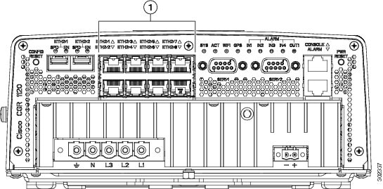
Connecting the Ethernet Ports
The router features four Fast Ethernet (FE) ports and two Gigabit Ethernet (GE) ports for connecting the router to an Ethernet network through a hub or switch.
■![]() See Figure 1 for the Ethernet port locations.
See Figure 1 for the Ethernet port locations.
■![]() One or two Ethernet cables are typically provided with the router. Additional cables and transceivers can be ordered from Cisco. For ordering information, contact your reseller or Cisco customer service.
One or two Ethernet cables are typically provided with the router. Additional cables and transceivers can be ordered from Cisco. For ordering information, contact your reseller or Cisco customer service.
■![]() The GE ports (ETH 2/1 and ETH 2/2) have identical labels to the SFP ports because the SFP ports share physical ports with the GE ports. For detailed information about how to use these ports (called combo ports), see Combo Ports.
The GE ports (ETH 2/1 and ETH 2/2) have identical labels to the SFP ports because the SFP ports share physical ports with the GE ports. For detailed information about how to use these ports (called combo ports), see Combo Ports.
Warning: Do not work on the system or connect or disconnect cables during periods of lightning activity. Statement 1001
|
|
|
|
|
|---|---|
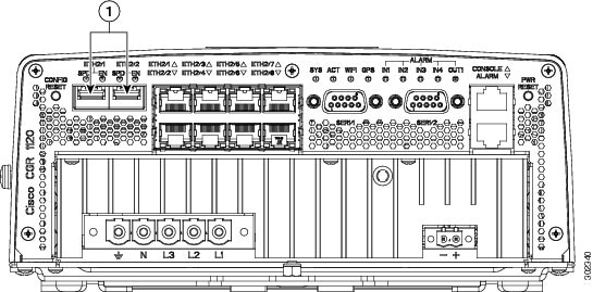
Connecting the SFP Ports
Small Form-Factor Pluggable (SFP) modules are devices that plug into the router SFP connectors shown in Figure 2. The transceiver connects the electrical circuitry of the module with the optical or copper network.
The SFP module used on each port must match the wavelength specifications on the other end of the cable, and the cable must not exceed the stipulated cable length for reliable communications.
Use only Cisco SFP transceiver modules with the router. Each SFP transceiver module supports the Cisco Quality Identification (ID) feature which allows a Cisco switch or router to identify and validate that the transceiver module is certified and tested by Cisco.
Warning: Class 1 laser product. Statement 1008
Caution: Do not remove the dust plugs from the fiber-optic SFP module port or the rubber caps from the fiber-optic cable until you are ready to connect the cable. The plugs and caps protect the SFP module ports and cables from contamination and ambient light.
Caution: Cisco recommends that you not install or remove the SFP module while the fiber-optic cable is attached to it because of the potential damage to the cables, to the cable connector, or to the optical interfaces in the SFP module. Disconnect the cable before you remove or install an SFP module.
Materials and Tools You Supply
You must provide these tools and materials to install the SFP transceiver module:
■![]() Wrist strap or other personal grounding device to prevent ESD occurrences.
Wrist strap or other personal grounding device to prevent ESD occurrences.
■![]() Antistatic mat or antistatic foam to set the transceiver on.
Antistatic mat or antistatic foam to set the transceiver on.
■![]() Fiber-optic end-face cleaning tools and inspection equipment. For complete information on inspecting and cleaning fiber-optic connections, see the white-paper document at this URL:
Fiber-optic end-face cleaning tools and inspection equipment. For complete information on inspecting and cleaning fiber-optic connections, see the white-paper document at this URL:
http://www.cisco.com/en/US/tech/tk482/tk876/technologies_white_paper09186a0080254eba.shtml
Connecting
This section describes how to install SFP modules. SFP modules are inserted into the SFP ports shown in Figure 2.
You can connect SFP modules to these ports while the router is operating normally. The SFP ports are labeled ETH 1/2 and ETH 2/2.
When installing or removing SFP modules, observe these guidelines:
■![]() Removing and installing an SFP module can shorten its useful life. Do not remove and insert any module more often than is absolutely necessary.
Removing and installing an SFP module can shorten its useful life. Do not remove and insert any module more often than is absolutely necessary.
■![]() To prevent ESD damage, follow your normal board and component handling procedures when connecting cables to the switch and other devices.
To prevent ESD damage, follow your normal board and component handling procedures when connecting cables to the switch and other devices.
1.![]() Attach an ESD-preventive wrist strap to your wrist and to a bare metal surface.
Attach an ESD-preventive wrist strap to your wrist and to a bare metal surface.
2.![]() For fiber-optic SFP modules, remove the dust plugs and store them in a clean location for reuse.
For fiber-optic SFP modules, remove the dust plugs and store them in a clean location for reuse.
3.![]() Position the SFP transceiver module in front of the socket opening, and insert the SFP into the socket until you feel the connector latch into place.
Position the SFP transceiver module in front of the socket opening, and insert the SFP into the socket until you feel the connector latch into place.
4.![]() Remove the dust plugs from the network interface cable LC connectors.
Remove the dust plugs from the network interface cable LC connectors.
5.![]() Inspect and clean the LC connector's fiber-optic end-faces.
Inspect and clean the LC connector's fiber-optic end-faces.
6.![]() Remove the dust plugs from the SFP transceiver module optical bores.
Remove the dust plugs from the SFP transceiver module optical bores.
7.![]() Attach the network interface cable connector to the SFP transceiver module.
Attach the network interface cable connector to the SFP transceiver module.
Related Information
■![]() For supported SFP modules, see Router Hardware Description.
For supported SFP modules, see Router Hardware Description.
■![]() For detailed information on connecting the SFP module cables to the network, see Cisco.com for the documentation for your SFP module.
For detailed information on connecting the SFP module cables to the network, see Cisco.com for the documentation for your SFP module.
|
|
Verify Ethernet Connection with System Software CLI
Note: The show interface command works on routers using the Cisco CG-OS or Cisco IOS operating systems. The example shown is for a router using a CG-OS operating system.
To verify that the router has been successfully installed and connected to the network, use the show interface command to confirm that the router Ethernet interface is up.
For more information about using the show interface command, see the Cisco 1000 Series Connected Grid Routers Software Configuration Guide.
Additional Router Connections
This section provides information about making other router cable connections. Follow the procedures in this section based on your network configuration and requirements. This section contains these procedures:
■![]() Installing Modules and Antennas
Installing Modules and Antennas
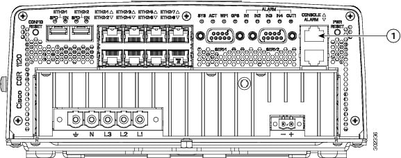
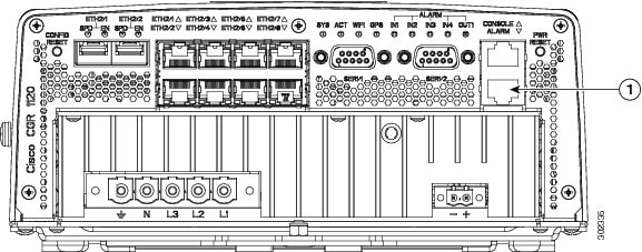
Connecting the Console Port
To configure the router through the Cisco IOS command-line interface (CLI), you must establish a connection between the router console port and either a terminal or a PC. The console port is located on the router exterior (Figure 3) and is labeled CON.
Use this port to connect a PC terminal, enabling you to log directly into the router system software to perform configuration or other commands.
Figure 3 Console Port (Item 1)
|
|
Connecting
This section describes how to connect a PC terminal to the console port.
When a terminal is connected to the console port, you can connect directly to the router and configure it. You can connect a PC terminal to this port while the router is operating normally.
To connect a PC terminal to the router, you must provide:
■![]() RJ-45-to-RJ-45 rollover cable
RJ-45-to-RJ-45 rollover cable
■![]() One of the following adapters, depending on the port type of the terminal device: RJ-45-to-DB-25 female DTE adapter or RJ-45-to-DB-9 female DTE adapter (labeled TERMINAL).
One of the following adapters, depending on the port type of the terminal device: RJ-45-to-DB-25 female DTE adapter or RJ-45-to-DB-9 female DTE adapter (labeled TERMINAL).
To connect a PC or PC terminal to the console port:
1.![]() Connect one end of the RJ-45-to-RJ-45 rollover cable to the console port on the router.
Connect one end of the RJ-45-to-RJ-45 rollover cable to the console port on the router.
2.![]() Connect the adapter you provide to the other end of the RJ-45 cable.
Connect the adapter you provide to the other end of the RJ-45 cable.
Related Information
■![]() For information about starting a terminal session over the console port with Microsoft Windows, Mac OS X, or Linux, see Starting a Router Terminal Session.
For information about starting a terminal session over the console port with Microsoft Windows, Mac OS X, or Linux, see Starting a Router Terminal Session.
■![]() For more information about this port, see Router Hardware Description.
For more information about this port, see Router Hardware Description.
Connecting the Serial Port
Before you connect a device to the router serial port (Figure 4), you need to know the following:
■![]() Type of device, data terminal equipment (DTE) or data communications equipment (DCE)
Type of device, data terminal equipment (DTE) or data communications equipment (DCE)
■![]() Type of connector, male or female, required to connect to the device
Type of connector, male or female, required to connect to the device
■![]() Signaling standard required by the device
Signaling standard required by the device
These are the most common devices connected to the router serial ports:
Connecting
■![]() You must provide or purchase separately the correct serial cable. The cable does not ship with the router. Contact your Cisco reseller to purchase the correct cable from Cisco.
You must provide or purchase separately the correct serial cable. The cable does not ship with the router. Contact your Cisco reseller to purchase the correct cable from Cisco.
■![]() You can connect a device to this port while the router is operating normally.
You can connect a device to this port while the router is operating normally.
Related Information
For more information about this port, including supported standards and signaling, see Router Hardware Description.
Figure 4 Serial Ports (Item 1)
|
|
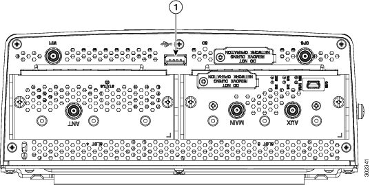
Connecting the USB Port
You can connect an optional USB device to the router USB port (Figure 5), which will provide power to the USB device. You can also connect USB devices that are powered by an external source, such as an AC adapter or batteries.
Connecting
■![]() You can connect devices to the USB port while the router is operating normally.
You can connect devices to the USB port while the router is operating normally.
■![]() The USB port is labeled with universal USB icon.
The USB port is labeled with universal USB icon.
■![]() Depending on the USB devices you connect to these ports, you might require a USB extension cable to connect devices to these ports.
Depending on the USB devices you connect to these ports, you might require a USB extension cable to connect devices to these ports.
■![]() To prevent connected USB devices from being stolen or accidentally removed, secure any connected USB device with a locking mechanism designed for this purpose.
To prevent connected USB devices from being stolen or accidentally removed, secure any connected USB device with a locking mechanism designed for this purpose.
Related Information
For detailed information about these ports, including supported USB standards and power output, see Router Hardware Description.
|
|
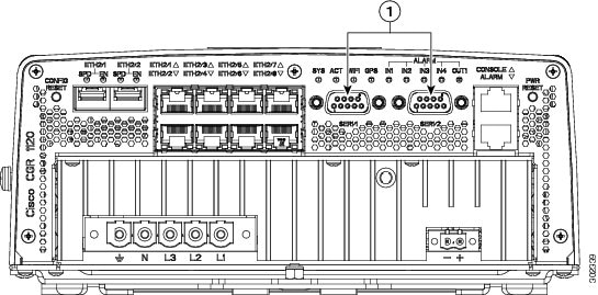
Connecting the Alarm Port
The alarm port provides data about fatal or severe errors that can cause the system software to crash.
The alarm port is connected to a normally closed solid state relay. Cisco CG-OS writes to a hardware port and the relay contact opens. If the system enters into a ROM monitor (ROMmon) or watchdog reset state, the relay contacts close. The closing contacts alert the alarm annunciator or monitor that a Cisco CG-OS crash has occurred.
If interfaces fail or other non-fatal errors occur, the alarm port does not respond. Continue to use SNMP to manage these types of errors.
Connecting
■![]() You can connect this port while the router is operating normally.
You can connect this port while the router is operating normally.
■![]() If you use an alarm system on your network, connect the alarm port to an alarm system with an alarm cable that you provide.
If you use an alarm system on your network, connect the alarm port to an alarm system with an alarm cable that you provide.
Related Information
Router Hardware Description includes detailed information about this port, including:
|
|
SD Flash Memory Module Card
For detailed information about the router SD Flash Memory Module card, including specifications, supported SD cards, and installation procedures, see Using the SD Flash Memory Module. For information about the antennas that ship with the router, see Using the SD Flash Memory Module.
|
|
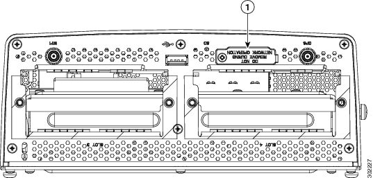
Installing Modules and Antennas
The router supports up to two Cisco Connected Grid modules. Each module requires one or two antennas, which are installed on the module or near the router.
Related Information
■![]() For information about supported router antennas, see About Connected Grid Antennas.
For information about supported router antennas, see About Connected Grid Antennas.
■![]() For information about supported modules, see About Connected Grid Modules.
For information about supported modules, see About Connected Grid Modules.
■![]() For detailed installation instructions for all Connected Grid modules and antennas, see the documentation on Cisco.com at: www.cisco.com/go/cg-modules
For detailed installation instructions for all Connected Grid modules and antennas, see the documentation on Cisco.com at: www.cisco.com/go/cg-modules
 Feedback