Installing the Router

This chapter provides procedures for installing the Cisco Catalyst 8500 Series Edge Platform on an equipment shelf, tabletop, or in an equipment rack.

Installation Instructions


Warning


Statement 1071—Warning Definition

IMPORTANT SAFETY INSTRUCTIONS

This warning symbol means danger. You are in a situation that could cause bodily injury. Before you work on any equipment, be aware of the hazards involved with electrical circuitry and be familiar with standard practices for preventing accidents. Use the statement number provided at the end of each warning to locate its translation in the translated safety warnings that accompanied this device.

SAVE THESE INSTRUCTIONS


Note


Statement 1056—Warning Definition

IMPORTANT SAFETY INSTRUCTIONS

Invisible laser radiation may be emitted from the fiber cable or connector. Do not view with optical instruments. Viewing the laser output with certain optical instruments (for example, eye loupes, magnifiers, and microscopes) within a distance of 100 mm may pose an eye hazard.


Note


Statement 1255—Warning Definition

IMPORTANT SAFETY INSTRUCTIONS

Pluggable optical modules comply with IEC 60825-1 Ed. 3 and 21 CFR 1040.10 and 1040.11 with or without exception for conformance with IEC 60825-1 Ed. 3 as described in Laser Notice No. 56, dated May 8, 2019.


Warning


Statement 1004—Installation Instructions

Read the installation instructions before using, installing or connecting the system to the power source.


Note


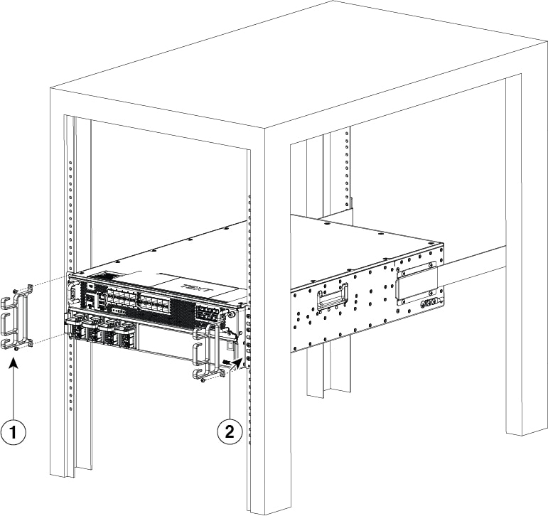
Proceed with the installation if you have already unpacked your chassis and read all the site requirements for your new equipment.


Guidelines for Installation

The chassis should already be in the area where you want to install it. If you have not determined where to install your chassis,

  • C8500-12X4QC and C8500-12X requires at least 3 inches (7.62 cm) and C8500-20X6C requires at least 5.25 inches (13.335 or 13.34 cm) of clearance at the inlet and exhaust vents (the front and rear sides of the chassis) for installing on a tabletop. The Cisco Catalyst 8500 Series Edge Platforms requires a minimum of 1.75 inches or 4.45 cm rack units of vertical rack space. Measure the proposed rack location before mounting the chassis in the rack.

  • The chassis should be installed off the floor. Dust that accumulates on the floor is drawn into the interior of the router by the cooling fans. Excessive dust inside the router can cause overtemperature conditions and component failures.

  • There must be approximately 19 inches (48.3 cm) of clearance at the front and rear of both the C8500-12X4QC and C8500-12X chassis and 19 inches (48.3 cm) of clearance at the front, 12 inches at the rear for C8500-20X6C chassis to install and replace FRUs, or to access network cables and equipment.

  • Maintain a minimum clearance of 3 inches on the front and back sides of the chassis for the cooling air inlet and exhaust ports, respectively. Avoid placing the chassis in an overly congested rack or directly next to another equipment rack; the heated exhaust air from other equipment can enter the inlet air vents and cause an overtemperature condition inside the router.

  • The chassis needs adequate ventilation. Do not install it in an enclosed cabinet where ventilation is inadequate.

  • Keep the cable-management bracket ready if you plan to install it on the front of the chassis.

  • Ensure that an adequate chassis ground (earth) connection exists for your router chassis (see the "Attaching a Chassis Ground Connection" section).

Installing the Router on a Standalone Equipment Shelf

Procedure


Step 1

Remove any debris and dust from the equipment shelf or platform, as well as the surrounding area.

Step 2

Lift the chassis into position on the equipment shelf.

Note


Step 3 through Step 9 are optional if you are installing the Cisco Catalyst 8500 Series Edge Platforms on a rack shelf. The chassis rack-mount brackets must be installed prior to installing the cable-management brackets.

Step 3

Attach the front rack-mount brackets. Locate the threaded holes in the front sides of the chassis (first holes beyond the vent holes) and use the package of black screws that shipped with the chassis.

Step 4

Align the front rack-mount bracket to one side of the chassis.

Step 5

Insert and tighten the screws on one side.

Step 6

Repeat Step 3 through Step 5 on the other side of the chassis. Use all the screws to secure the rack-mount brackets to the chassis.

Step 7

Gather the two cable-management brackets and screws shipped with your chassis.

Step 8

Screw a cable-management bracket to each side of the rack-mount brackets that are attached to the chassis. Use two screws for each cable-management bracket. Use a screw from the package of four screws.

Note


Ensure that the cable-management U feature device has the open end pointing outwards when you attach it to the chassis.

Step 9

Check that all the screws are securely tightened.


Guidelines for Rack Installation

The Cisco Catalyst 8500 Series Edge Platforms can be installed in the following rack types:

  • Two-post rack, either 19 inch or 23 inch. Inner clearance (the width between the inner sides of the two posts or rails) must be at least 19 inches (48.26 cm). Airflow through the chassis is from front to back.

  • Four-post, 19-inch equipment rack. Inner clearance (the width between the inner sides of the two posts or rails) must be at least 19 inches (48.26 cm). Airflow through the chassis is from front to back.

C8500-12X4QC and C8500-12X can be installed with both front or rear rack-mount brackets and C8500-20X6C must be installed with both front and rear rack-mount brackets.

When planning your rack installation, consider the following guidelines:

  • The Cisco Catalyst 8500 Series Edge Platforms requires a minimum of 1.75 inches or 4.45 cm rack units of vertical rack space. The Cisco Catalyst 8500 Series Edge Platforms requires a minimum of 3.5 inches or 8.9 cm rack units of vertical rack space. Measure the proposed rack location before mounting the chassis in the rack.

  • Before using a particular rack, check for obstructions (such as a power strip) that could impair rack-mount installation. If a power strip does impair a rack-mount installation, remove the power strip before installing the chassis, and then replace it after the chassis is installed.

  • Allow sufficient clearance around the rack for maintenance. If the rack is mobile, you can push it back near a wall or cabinet for normal operation and pull it out for maintenance (installing or moving cards, connecting cables, or replacing or upgrading components). Otherwise, allow 19 inches (48.3 cm) of clearance to remove field-replaceable units.

  • Maintain a minimum clearance of 3 inches on the front and back sides of the chassis for the cooling air inlet and exhaust ports, respectively. Avoid placing the chassis in an overly congested rack or directly next to another equipment rack; the heated exhaust air from other equipment can enter the inlet air vents and cause an overtemperature condition inside the router.


    Caution


    To prevent chassis overheating, never install a Cisco Catalyst 8500 Series Edge Platforms in an enclosed space that is not properly ventilated or air conditioned.


    Caution


    The recommended torque for rack mount bracket screws is 8 in-lbs.


  • Always install heavier equipment in the lower half of a rack to maintain a low center of gravity to prevent the rack from falling over.

  • Install and use the cable-management brackets included with the Cisco Catalyst 8500 Series Edge Platforms to keep cables organized and out of the way of the cards and processors. Ensure that cables from other equipment already installed in the rack do not impair access to the cards or require you to disconnect cables unnecessarily to perform equipment maintenance or upgrades.

  • Provide an adequate chassis ground (earth) connection for your router chassis.

Verifying Rack Dimensions

Before you install the chassis, measure the space between the vertical mounting flanges (rails) on your equipment rack to verify that the rack conforms to the measurements shown in the following figure.

Figure 1. Verifying Equipment Rack Dimensions

Procedure


Step 1

Mark and measure the distance between two holes on the left and right mounting rails.

The distance should measure 18.31 inches ± 0.06 inches (46.5 cm ± 0.15 cm).

Note


Measure for pairs of holes near the bottom, middle, and top of the equipment rack to ensure that the rack posts are parallel.

Step 2

Measure the space between the inner edges of the left front and right front mounting flanges on the equipment rack.

The space must be at least 17.7 inches (45 cm) to accommodate the chassis that is 17.25 inches (43.8 cm) wide and fits between the mounting posts on the rack.


Attaching the Front Rack-Mount Brackets

Before you begin

Before installing the chassis in the rack, you must install the rack-mount brackets on each side of the chassis.

Determine where in the rack you want the chassis to be mounted. If you are mounting more than one chassis in the rack, then start from the bottom up or the center of the rack. The following figure shows the brackets attached to the chassis. Depending on the bracket holes you use, the chassis may protrude in the rack.


Note


The cable-management brackets are attached to the chassis after you install the chassis rack-mount brackets on the chassis and mount the chassis in the rack.


Procedure


Step 1

Locate the threaded holes on the side of the chassis. Ensure that you hold the front rack-mount bracket with the ear and holes facing outward and towards the front of the chassis.

The following figures show where to attach the front rack-mount brackets to the Cisco Catalyst 8500 Series Edge Platforms.

Figure 2. Attaching the Front Rack-Mount Brackets to the Cisco Catalyst 8500 Series Edge Platform

Step 2

Position the front rack-mount bracket top hole with the chassis, first top hole behind the side vent holes.

Step 3

Insert and tighten the black screws on one side.

Step 4

Repeat Step 1 through Step 3 on the other side of the chassis. Use black screws to secure the rack-mount brackets to the chassis.


Attaching the Rear Rack-Mount Brackets

Before you begin


Note


This procedure is not required if you are installing the chassis in a two-post rack.


Before installing the chassis in a four-post rack, you must install the rear rack-mount brackets on each side of the chassis.

Determine where in the rack you want the chassis to be mounted. If you are mounting more than one chassis in the rack, then start from the bottom up or the center of the rack. The following figure shows the brackets attached to the chassis.

Procedure


Step 1

Locate the threaded holes on the side of the chassis. Ensure that you hold the rear rack-mount bracket with the ear and holes facing outward and towards the rear of the chassis.

The following figures show where to attach the rear rack-mount brackets to the Cisco Catalyst 8500 Series Edge Platforms.

Figure 3. Attaching the Rear Rack-Mount Brackets to the Cisco Catalyst 8500 Series Edge Platforms

Step 2

Position the rear rack-mount bracket with the chassis.

Step 3

Insert the black screws on one side. Do not fully tighten the screws.

The rear bracket holes are slotted to allow for adjustment. Do not fully tighten the screws until the chassis is installed in the four-post rack.

Step 4

Repeat Step 1 through Step 3 on the other side of the chassis. Use black screws to secure the rack-mount brackets to the chassis.


Mounting the Router in the Rack

After installing the rack-mount brackets on the chassis, mount the chassis by securing the rack-mount brackets to two posts or mounting strips in the rack using the screws provided. Because the rack-mount brackets support the weight of the entire chassis, ensure that you use all the screws to fasten the two rack-mount brackets to the rack posts.

Two-Post Rack Installation


Warning


Statement 1006—Chassis Warning for Rack-Mounting and Servicing

To prevent bodily injury when mounting or servicing this unit in a rack, you must take special precautions to ensure that the system remains stable. The following guidelines are provided to ensure your safety:

  • This unit should be mounted at the bottom of the rack if it is the only unit in the rack.

  • When mounting this unit in a partially filled rack, load the rack from the bottom to the top with the heaviest component at the bottom of the rack.

  • If the rack is provided with stabilizing devices, install the stabilizers before mounting or servicing the unit in the rack.


The Cisco C8500 Series Catalyst Edge Router can be installed on a two-post rack, either 19 inch or 23 inch. We recommend that you allow at least 1 or 2 inches (2.54 or 5.08 cm) of vertical clearance between the router and any equipment directly above and below it.

Procedure


Step 1

On the chassis, ensure that all the screw fasteners on the installed components are securely tightened.

Step 2

Make sure that your path to the rack is unobstructed. If the rack is on wheels, ensure that the brakes are engaged or that the rack is otherwise stabilized.

Step 3

(Optional) Install a shelf in the rack to support the Cisco Catalyst 8500 Series Edge Platforms. If you use a shelf, it helps support the chassis while you secure it to the rack.

Note


If you are using a shelf, place the chassis on the shelf and slightly raise the front of the chassis to align the mounting bracket holes with the rack post holes while allowing the bottom of the chassis to rest on the shelf.

Step 4

With two people, lift the chassis into position between the rack posts.

Step 5

Align the mounting bracket holes with the rack post holes and attach the chassis to the rack.

Step 6

Position the chassis until the rack-mounting flanges are flush against the mounting rails on the rack.

Tip


To allow space to attach the cable-management brackets to the chassis in the rack easily, use the rack-mount bracket ear holes mentioned in Steps 7 and 8.

Step 7

Hold the chassis in position against the mounting rails in the equipment rack and follow these steps:

  1. Insert the bottom screw into the second hole up from the bottom of the rack-mount ear and use a hand-held screwdriver to tighten the screw to the rack rail.

    Tip


    To make installation easier, insert one screw at the bottom of the chassis and the next screw at the top of the chassis diagonally from the first screw.

  2. Insert the top screw into the second hole from the top of the rack-mount ear diagonally from the bottom screw and tighten the screw to the rack rail.

  3. Insert the rest of the screws to secure the chassis to the rack equipment.

Step 8

Tighten all the screws on each side to secure the chassis to the equipment rack.

The following figures show the Cisco Catalyst 8500 Series Edge Platform on a two-post equipment rack.

Figure 4. Cisco C8500 Series Catalyst Edge Router Installed on a Two-Post Equipment Rack

1

Rack equipment rail

2

Rack mount bracket ear and screws


Four-Post Rack Installation

Procedure


Step 1

(Optional) Install a shelf in the rack to support C8500-12X4QC, C8500-12X and C8500-20X6C. If you use a shelf, it helps support the chassis while you secure it to the rack.

Note


If you are using a shelf, place the chassis on the shelf and slightly raise the front of the chassis to align the mounting bracket holes with the rack post holes while allowing the bottom of the chassis to rest on the shelf.

Step 2

With two people, lift the chassis into position between the rack posts.

Step 3

Position the chassis until the rack-mounting flanges are flush against the mounting rails on the rack.

Note


Use the second hole up from the bottom of the rack-mount bracket and the second hole down from the top of the rack-mount bracket. This will make it easier to attach the cable-management bracket to the chassis in the equipment rack.

Step 4

Hold the chassis in position against the mounting rails while the second person finger-tightens a screw to the rack rails on each side of the chassis.

Step 5

Finger-tighten screws to the rack rails on each side of the chassis.

Step 6

Tighten all the screws on each side to secure the chassis to the equipment rack.

Figure 5. C8500-12X4QC and C8500-12X in a Four-Post Rack—Front and Rear Rack-Mounting

1

Rear rack equipment rail

3

Front rack mount bracket ear and screws

2

Rear rack mount bracket ear and screws

Figure 6. Cisco 8500-20X6C in a Four-Post Rack—Front and Rear Rack-Mounting

1

Rear rack equipment rail

3

Front rack equipment rail

2

Rear rack mount bracket and screws

4

Front rack mount bracket and screws

Step 7

Use a level to verify that the tops of the two brackets are level, or use a measuring tape to verify that both brackets are the same distance from the top of the rack rails.


Attaching the Cable Management Bracket

The cable management brackets should be mounted to each rack-mount bracket on the chassis to provide cable management to both sides of the chassis (parallel with card orientation). These brackets are screw-mounted to the rack-mount brackets to allow easy installation and removal of cables.

The cable-management brackets for the Cisco Catalyst 8500 Series Edge Platform contain one independent cable-management U-type feature with two screws for each bracket.


Note


Make certain that the cable-management bracket "U" feature is facing upwards when you attach it to the C8500-12X4QC or C8500-12X chassis.


Procedure


Step 1

Align the cable-management bracket to the rack-mount bracket on one side of the Cisco Catalyst 8500 Series Edge Platform. The cable-management bracket aligns to the top hole of the chassis rack-mount bracket.

Step 2

Using a Phillips screwdriver, insert one screw through the top screw hole of the cable-management bracket and into the chassis rack-mount bracket and tighten the screw.

Note


Use the package of screws that came with your chassis containing four screws.

The following figures show where to attach the cable-management brackets to the Cisco Catalyst 8500 Series Edge Platforms.

Figure 7. Attaching the Cable-Management Brackets to C8500-20X6C

1

Front cable-management bracket.

2

Front-rack mount bracket.

Step 3

Insert a screw through the hole in the cable management bracket and tighten using a Phillips screwdriver.

Step 4

Repeat Step 1 through Step 3 for the other side of the chassis.


Chassis Ground Connection

Connecting the Cisco Catalyst 8500 Series Edge Platform chassis to ground is required for all DC powered installations and any AC powered installation where compliance with Telcordia grounding requirements is necessary.


Warning


Statement 1024—Ground Conductor

This equipment must be grounded. To reduce the risk of electric shock, never defeat the ground conductor or operate the equipment in the absence of a suitably installed ground conductor. Contact the appropriate electrical inspection authority or an electrician if you are uncertain that suitable grounding is available.


Before you connect power or turn on power to your chassis, you must provide an adequate chassis ground (earth) connection for the chassis. A chassis ground connector is provided on Cisco Catalyst 8500 Series Edge Platform. There is a stud on the rear left side of the chassis.

When customer properly install the chassis in a grounded rack, the switch is grounded because it has a metal-to-metal connection to the rack. Alternatively, customer can ground the chassis by using a customer-supplied grounding cable that meets your local and national installation requirements.

For U.S. installations, 6-AWG wire is recommended. Connect the grounding cable to the chassis with a grounding lug and to the facility ground.


Caution


The grounding wire should always be the first to be installed or connected and the last to be removed or disconnected.


Note


An electrical conducting path shall exist between the product chassis and the metal surface of the enclosure or rack in which it is mounted, or to a grounding conductor. Electrical continuity shall be provided by using thread-forming type mounting screws that remove any paint or non-conductive coatings, and establish a metal-to-metal contact. Any paint or non-conductive coatings shall be removed on the surfaces between the mounting hardware and the enclosure or rack. The surfaces shall be cleaned and an antioxidant applied before installation.


Have the recommended tools and supplies available before you begin this procedure.

Recommended Tools and Supplies

The following tools, equipment, and supplies are necessary to connect the system ground to the chassis:

  • Phillips screwdriver

  • 3.5-mm flat blade screwdriver (Phoenix # 1205053 or equivalent 3.5-mm flat blade)

  • Dual-lug chassis ground component

  • Grounding wire

Attaching a Chassis Ground Connection

Procedure


Step 1

Use the wire stripper to strip one end of the AWG #6 wire approximately 0.75 inches (19.05 mm).

Step 2

Insert the AWG #6 wire into the open end of the grounding lug.

Step 3

Use the crimping tool to carefully crimp the wire receptacle around the wire. This step is required to ensure a proper mechanical connection.

Step 4

Locate the chassis ground connector on the side of your chassis.

Step 5

Insert the two screws through the holes in the grounding lug.

The following figures show how to attach a grounding lug to the chassis ground connector.

Figure 8. Attaching a Grounding Lug to the C8500-12X4QC and C8500-12X Chassis Ground Connector

1

Chassis ground lead wire

3

Ground screws

2

Grounding lug

4

Chassis ground connector holes

Figure 9. Attaching a Grounding Lug to the C8500-20X6C Chassis Ground Connector

1

Chassis ground connector holes

3

Ground screws

2

Grounding lug

Step 6

Use the Number 2 Phillips screwdriver to carefully tighten the screws until the grounding lug is held firmly to the chassis. Do not over tighten the screws.

Step 7

Connect the opposite end of the grounding wire to the appropriate grounding point at your site to ensure an adequate chassis ground.


Connecting Cables

Keep the following guidelines in mind when connecting any external cable to the Cisco Catalyst 8500 Series Edge Platform:

  • To reduce the chance of interference, avoid crossing high-power lines with any interface cables.

  • Verify all the cabling limitations (particularly distance) before powering on the system.

Connecting the Console Port Cables

The router uses RJ-45 port to attach a console terminal. The router has an asynchronous serial (EIA/TIA-232) RJ-45 console port labeled CON on its front panel. You can connect this port to most types of video terminals with a console cable kit that is included with your router. The console cable kit contains:

  • One RJ-45-to-RJ-45 crossover cable

A crossover cable reverses pin connections from one end to the other. In other words, it connects pin 1 (at one end) to pin 8 (at the other end), pin 2 to pin 7, pin 3 to pin 6, and so on. You can identify a crossover cable by comparing the two modular ends of the cable. Hold the cable ends in your hand, side-by-side, with the tabs at the back. Ensure that the wire connected to the outside (left) pin of the left plug (pin 1) is the same color as the wire connected to the outside (right) pin of the right plug (pin 8).

The console port is an asynchronous serial ports; devices connected to this ports must be capable of asynchronous transmission. Baud rates for the RJ-45 console port are 1200, 2400, 4800, 9600, 19200, 38400, 57600, and 115200 bps.

Before connecting to the console interface on the router using a terminal or PC, perform the following steps:

Procedure


Step 1

Before connecting a terminal to the console port, configure the terminal to match the chassis console port as follows: 9600 baud, 8 data bits, no parity, 1 stop bits (9600 8N1).

Step 2

Connect one end of the RJ-45 cable to the serial RJ-45 console port (CON) .

Note


For information about how to change the default settings to meet the requirements of your terminal or host, see the Cisco IOS Terminal Services Configuration Guide.

Step 3

After you establish normal router operation, you can disconnect the terminal.


Connecting to the USB 3.0 Console Interface

The USB 3.0 interface connects directly to the USB connector of a PC using a USB Type A to 5-pin micro USB Type-B cable. The USB 3.0 interface supports full speed (12Mbps) operation. The interface does not support hardware flow control.


Note


  • Always use shielded USB cables with a properly terminated shield. The USB serial console interface cable must not exceed 3 meters in length.

  • Only one interface can be active at a time. When a cable is plugged into the USB 3.0 interface, the RJ-45 port becomes inactive. Conversely, when the USB cable is removed from the USB 3.0 interface, the RJ-45 port becomes active.

  • 4-pin micro USB Type-B connectors are easily confused with 5-pin micro USB Type-B connectors. Note that only the 5-pin micro USB Type-B is supported.


The default parameters for the interface are 9600 baud, 8 data bits, no parity, and 1 stop bit.

For operation with a Microsoft Windows OS version older than Windows 7, the Cisco Windows USB Console Driver must be installed on any PC connected to the interface. If the driver is not installed, prompts guide you through a simple installation process.

The Cisco Windows USB Console Driver allows plugging and unplugging the USB cable from the interface without affecting Windows HyperTerminal operations. No special drivers are needed for Mac OS X or Linux.

Management Ethernet Port Cable Connection


Caution


To comply with Class A emission requirements, a shielded Ethernet cable must be used for the connection.


Procedure


Step 1

Insert an Ethernet RJ-45 cable into the MGMT port.

Step 2

Insert the other end of the RJ-45 cable to your management device or network.