Installing an SSD
Before you begin
 Note |
The following section does not apply to the C8500-20X6C chassis. Do not remove the top cover of the C8500-20X6C chassis as it does not include any user serviceable parts. |
Ensure that you follow the guidelines in Preventing Electrostatic Discharge Damage
Procedure
|
Step 1 |
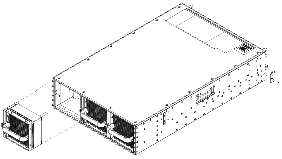
Ensure the router is powered off and all the power supplies are removed from the chassis. |
||
|
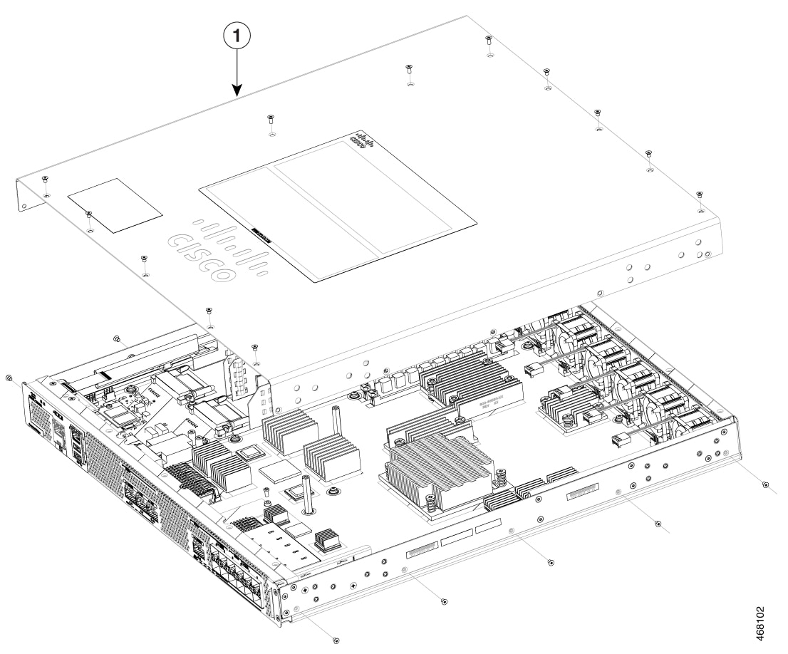
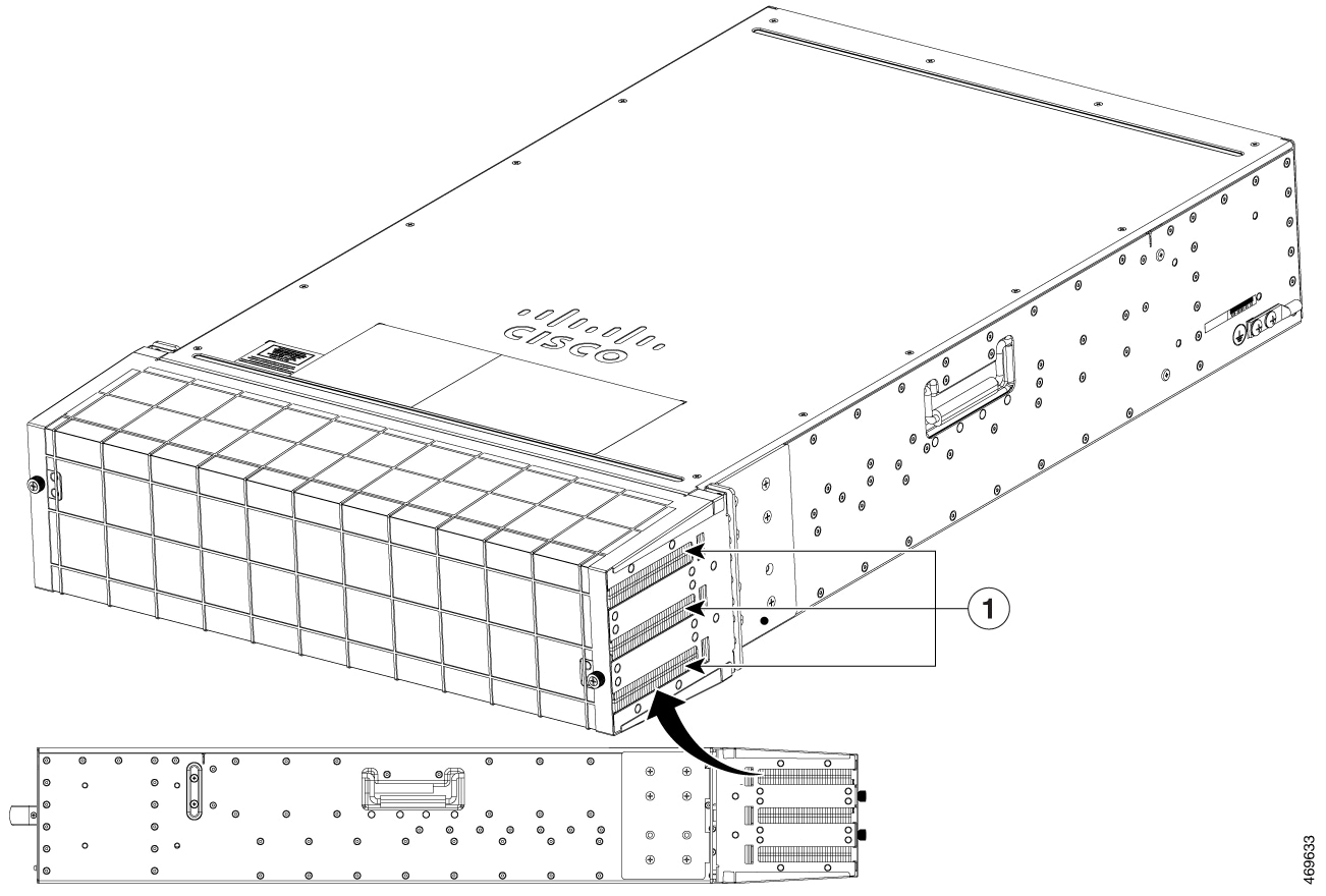
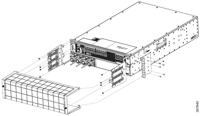
Step 2 |
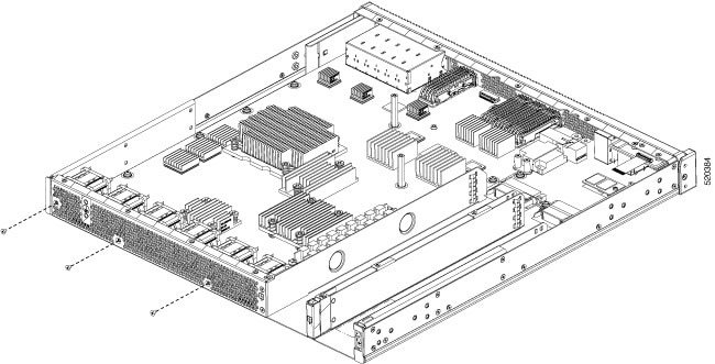
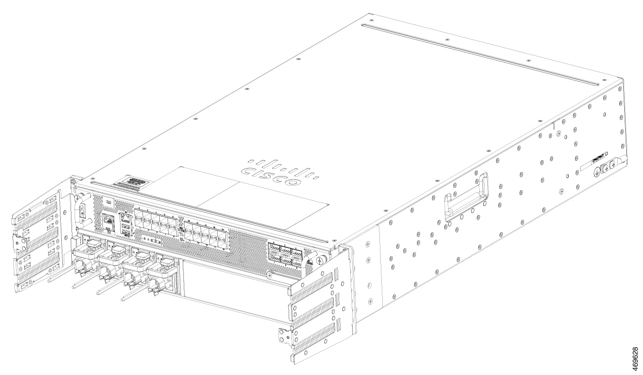
If the router is mounted on a rack, remove the screws from the rack mounting brackets. Remove all screws from the sides and
top of the chassis that secure the cover. There are 12 screws on the top and 5 screws on each side.
|
||
|
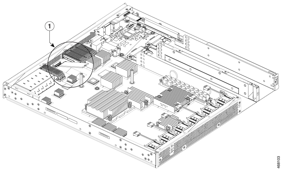
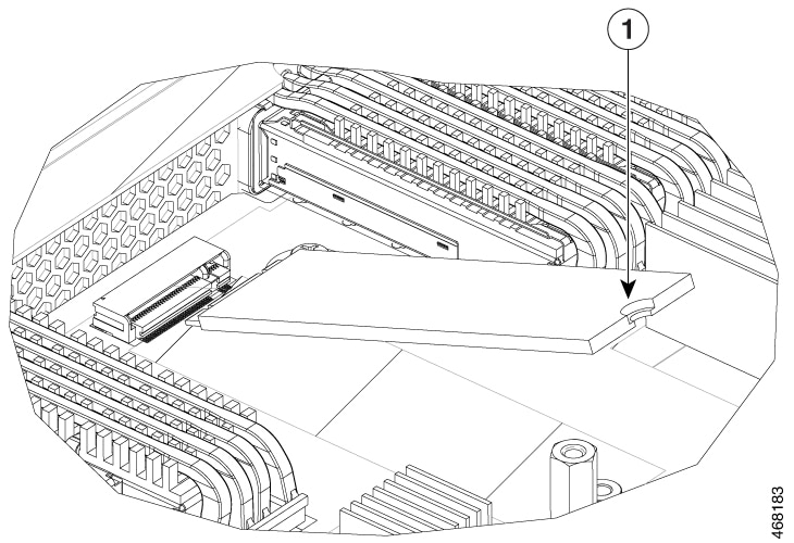
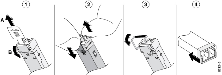
Step 3 |
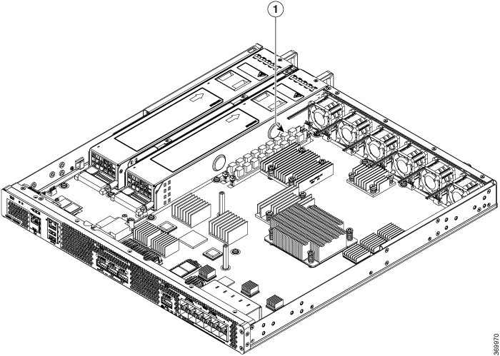
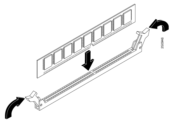
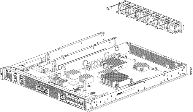
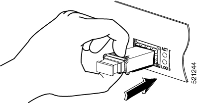
Locate the SSD slot. Carefully insert the SSD at approximately a 30 degree angle to seat the card in the connector. Rotate
the card downward until it rests on the small notch in the printed circuit board(PCB).
|
||
|
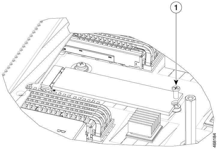
Step 4 |
Install the retention screw in the hole in the SSD and gently tighten to a torque to no greater than 5 in-lbs |
||
|
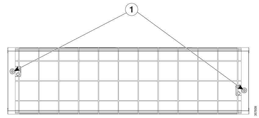
Step 5 |
Re-install the cover and replace all screws that were removed in step 1. |

 Feedback