Ethernet Virtual Connections Configuration

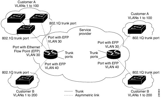
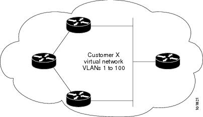
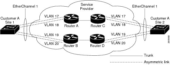
An Ethernet Virtual Connection (EVC) is defined by the Metro-Ethernet Forum (MEF) as an association between two or more user network interfaces that identifies a point-to-point or multipoint-to-multipoint path within the service provider network. An EVC is a conceptual service pipe within the service provider network. A bridge domain is a local broadcast domain that is VLAN-ID-agnostic. An Ethernet flow point (EFP) service instance is a logical interface that connects a bridge domain to a physical port or to an EtherChannel group.

An EVC broadcast domain is determined by a bridge domain and the EFPs that are connected to it. You can connect multiple EFPs to the same bridge domain on the same physical interface, and each EFP can have its own matching criteria and rewrite operation. An incoming frame is matched against EFP matching criteria on the interface, learned on the matching EFP, and forwarded to one or more EFPs in the bridge domain. If there are no matching EFPs, the frame is dropped.

You can use EFPs to configure VLAN translation. For example, if there are two EFPs egressing the same interface, each EFP can have a different VLAN rewrite operation, which is more flexible than the traditional switchport VLAN translation model.

This document describes how to configure EVC features.

For detailed information about the commands, see:

Supported EVC Features

  • Service instance—you create, delete, and modify EFP service instances on Ethernet interfaces.

  • Encapsulation—you can map traffic to EFPs based on:

    • 802.1Q VLANs (a single VLAN or a list or range of VLANs)

    • 802.1Q tunneling (QinQ) VLANs (a single outer VLAN and a list or range of inner VLANs)

    • Double-tagged frames mapped to EVC based on C-tags (wildcard S-Tags)

  • Bridge domains—you can configure EFPs as members of a bridge domain (up to 64 EFPs per bridge domain for bridge domain with BDIs.).

  • Rewrite (VLAN translation)

    • Pop symmetric

      pop 1 removes the outermost tag

      pop 2 removes the two outermost tags

      pop symmetric adds a tag (or 2 tags for pop 2 symmetric ) on egress for a push operation

    • Ingress push—The rewrite ingress tag push dot1q vlan-id symmetric command adds a tag to an ingress packet

    • QinQ with rewrite

    rewrite ingress tag push is supported on QoS with CoS Marking for EVCs on RSP2 module.


    Note


    Ingress push on Qos on for EVC is not supported on RSP1 module.


    Note


    EVC push is also supported on 802.1ad.


  • EVC forwarding

  • MAC address learning and aging

  • EVCs on EtherChannels

  • Hairpinning

  • Split horizon

  • Layer 2 protocol tunneling and QinQ

  • Bridging between EFPs

  • MSTP (MST on EVC bridge domain)

  • EFP statistics (packets and bytes)

  • QoS aware EVC/EFP per service instance

  • Static MAC Addresses

These Layer 2 port-based features can run with EVC configured on the port:

  • LACP

  • CDP

  • MSTP

  • EVC egress filtering

Limitations

Table 1. Feature History

Feature Name

Release Information

Feature Description

Support for Ethernet Flow Point (EFP) with Untagged Plus VLAN Range or List

Cisco IOS XE Cupertino 17.7.1

This feature supports an EFP service instance with untagged and IEEE 802.1Q encapsulation for a single Ethernet Virtual Circuit (EVC) on the RSP3 module. Prior to this release, a service instance supported only a single encapsulation type.

The following limitations apply when configuring EVC features:

  • Configuring the QoS policy-map with extended service instance ids of integers 4001–5000 is not supported on Cisco NCS 4202 router.

  • Egress filtering on ASIC results in packets loss for VLAN ranges below 5 and also the comma-separated VLANs are forwarded only with packets having the first VLAN. To avoid packet drops, ensure to configure a VLAN range value greater than 5.

  • From Cisco IOS XE Cupertino Release 17.7.1, an EFP service instance with untagged and IEEE 802.1Q encapsulation is supported for a single Ethernet Virtual Circuit (EVC), on the RSP 3 module, with the following limitations:

    • Support for the rewrite command is restricted to options, such as push dot1q and dot1ad .

    • An EFP service instance with untagged and IEEE 802.1QinQ encapsulation isn’t supported for a single EVC.

    • The Bridge Domain Interface (BDI) functionality isn’t supported on an EFP service instance.

    • Layer 2 CoS marking is supported only with the rewrite push command.

    • Egress filtering isn’t supported with the efp_feat_ext SDM template.

    • SADT isn’t supported over EFP with untagged VLAN.

  • If a service-instance on an interface has a list of VLAN (less than or equal to 5) and another service-instance on the same interface uses a VLAN, which is already included, then both the service-instances can forward the traffic in the RSP3 module without any issues. But, when you increase the size of VLAN list to more than 5 on the service-instance, then the service on the other service-instances will be affected.

  • Translate operations aren’t supported.

  • You can create a maximum of 8000 EVCs per interface. For more information, see section 16K EFP Support in the Quality of Service Configuration Guidelines, Cisco IOS XE 17 (Cisco ASR 900 Series).

  • You can create a maximum of 256 EFPs per bridge-domain.

  • A delay of 30-40 ms is observed while adding or removing the VLAN ID on any EFP for existing traffic on the RSP3 module.

  • The no mac address-table learning bridge-domain bridge-id global configuration command isn’t currently supported.

  • Only dot1q encapsulation is supported on trunk EFPs.

  • Priority tagging and encapsulation untagged aren’t supported under the same EFP on the RSP3 module.

  • BDI statistics is supported on the RSP3 module starting Cisco IOS XE Fuji 16.9.3 Release.

  • On the RSP3 module, the Trunk EFP doesn’t drop unallowed VLANs, when any other EFP doesn’t exist to filter the VLANs. The traffic for those VLANs is bridged across to the corresponding BD, if it exists.

  • Ingress mapping of Differentiated Services Code Point (DSCP) or Class of Service (CoS) to the C-CoS or S-CoS is supported.

  • Egress classification and queuing is based on DSCP or CoS.

  • Ethertype encapsulation and CoS value encapsulation aren’t supported on the RSP3 module.

  • For layer 2 VPN and VPLS, when one end is configured as "encapsulation default" and other end is configured without any rewrite options, the packets drop and these dropped packets are considered as “Output Drops”. This is an expected behavior.

    This behavior is applicable to Cisco RSP2 Module. This behavior isn’t seen in Cisco RSP1 and Cisco RSP3 Modules.

  • If a Layer3 bridge domain interface (BDI) is associated with a bridge domain, then 64 EFPs are supported on that bridge domain across a single or multiple interfaces on the RSP3 module.

  • Remote MEPs aren’t learnt when SH group 1 and SH group 2 are configured in the access EVC BD.

  • TCAM exhaustion message is displayed even when TEFP with 900 VLAN has a QoS policy that is configured to match a single VLAN. As a result, the TEFP scale is affected.

  • Configurable MAC isn’t supported on BDIs with multiple EFPs per port. If configured, it may lead to erroneous behaviour.

  • The following features aren’t supported on BDIs with multiple EFPs:

    • BFD

    • All Layer3 multicast features

    • PTP

    • DHCP snooping

  • 1024 EFPs per port are supported, which fall into the category of second or higher EFP configured under any BDI on that port.

  • Fast Reroute (FRR) isn’t supported on BDI with multiple EFPs.

  • By default, ARP throttling isn’t supported on RSP3 module as excess entries lead to error objects. You can use the arp entries interface-limit command to enable the throttle.

Ethernet Virtual Connections

You use the ethernet evc evc-id global configuration command to create an Ethernet virtual connection (EVC). The evc-id or name is a text string from 1 to 100 bytes. Entering this command puts the device into service configuration mode (config-srv) where you configure all parameters that are common to an EVC.

In this mode you can enter these commands:

  • default —Sets a command to its defaults

  • exit —Exits EVC configuration mode

  • no — Negates a command or sets its defaults

  • oam —Specifies the OAM Protocol

  • uni —Configures a count UNI under EVC

Service Instances and EFPs

Configuring a service instance on a Layer 2 port or EtherChannel creates a pseudoport or Ethernet flow point (EFP) on which you configure EVC features. Each service instance has a unique number per interface, but you can use the same number on different interfaces because service instances on different ports are not related.

If you have defined an EVC by entering the ethernet evc evc-id global configuration command, you can associate the EVC with the service instance (optional). There is no default behavior for a service instance.

Use the service instance number ethernet [name] interface configuration command to create an EFP on a Layer 2 interface or EtherChannel and to enter service instance configuration mode. You use service instance configuration mode to configure all management and control date plane attributes and parameters that apply to the service instance on a per-interface basis.

  • The service instance number is the EFP identifier, an integer from 1 to 4000.

  • The optional ethernet name is the name of a previously configured EVC. You do not need to enter an EVC name, but you must enter ethernet . Different EFPs can share the same name when they correspond to the same EVC. EFPs are tied to a global EVC through the common name.

When you enter service instance configuration mode, you can configure these options:

  • default —Sets a command to its defaults

  • description —Adds a service instance specific description

  • encapsulation —Configures Ethernet frame match criteria

  • ethernet —Configures Ethernet-lmi parameters

  • exit — Exits from service instance configuration mode

  • ip —Interface Internet Protocol config commands

  • ipv6 —IPv6 interface subcommands

  • l2protocol —Configures Layer 2 control protocol processing

  • mac —Commands for MAC address-based features

  • no —Negates a command or sets its defaults

  • service-policy —Attaches a policy-map to an EFP

  • shutdown —Takes the service instance out of service

    Enter the [no] shutdown service-instance configuration mode to shut down or bring up a service instance.

  • snmp —Modify SNMP service instance parameters

Encapsulation

Encapsulation defines the matching criteria that maps a VLAN, a range of VLANs, class of service (CoS) bits, Ethertype, or a combination of these to a service instance. You configure encapsulation in service instance configuration mode. You must configure one encapsulation command per EFP (service instance).

Use the encapsulation service-instance configuration mode command to set encapsulation criteria. Different types of encapsulations are default, dot1q, dot1ad, priority-tagged and untagged. Supported Ethertypes include ipv4, ipv6, pppoe-all, pppoe-discovery, and pppoe-session.

Encapsulation classification options also include:

  • outer tag VLAN

  • outer tag CoS

  • inner tag VLAN

  • inner tag CoS

  • payload ethertype

After you have entered an encapsulation method, these keyword options are available in service instance configuration mode:

  • bridge-domain —Configures a bridge domain

  • rewrite —Configures Ethernet rewrite criteria

Table 2. Supported Encapsulation Types

Description

encapsulation dot1q vlan-id [vlan-id[-vlan-id]]

Defines the matching criteria to be used to map 802.1Q frames ingress on an interface to the appropriate EFP. The options are a single VLAN, a range of VLANs, or lists of VLANs or VLAN ranges. VLAN IDs are 1 to 4094.

  • Enter a single VLAN ID for an exact match of the outermost tag.

  • Enter a VLAN range for a ranged outermost match.

encapsulation dot1q vlan-id second-dot1q vlan-id [vlan-id[-vlan-id]]

Double-tagged 802.1Q encapsulation. Matching criteria to be used to map QinQ frames ingress on an interface to the appropriate EFP. The outer tag is unique and the inner tag can be a single VLAN, a range of VLANs or lists of VLANs or VLAN ranges.

  • Enter a single VLAN ID in each instance for an exact match of the outermost two tags.

  • Enter a VLAN range for second-dot1q for an exact outermost tag and a ranged second tag.

encapsulation dot1q {any | vlan-id [vlan-id[-vlan-id]]} ext-etype ethertype

Ethertype encapsulation is the payload encapsulation type after VLAN encapsulation.

  • ethertype—The ext-etype string can have these values: ipv4, ipv6, pppoe-discovery, pppoe-session, or pppoe-all.

  • Matches any or an exact outermost VLAN or VLAN range and a payload ethertype.

encapsulation dot1q vlan_id cos cos_value second-dot1q vlan-id cos cos_value

CoS value encapsulation defines match criterion after including the CoS for the S-Tag and the C-Tag. The CoS value is a single digit between 1 and 7 for S-Tag and C-Tag.

You cannot configure CoS encapsulation with encapsulation untagged , but you can configure it with encapsulation priority-tag .

The result is an exact outermost VLAN and CoS match and second tag. You can also use VLAN ranges.

encapsulation dot1q any

encapsulation Matches any packet with one or more VLANs.

encapsulation dot1q add

encapsulation dot1q add inner vlan range

encapsulation dot1ad add

encapsulation dot1ad add inner vlan range

Adds one or more VLAN tag values for matching criteria. This command is also used with show run command when the encapsulation configuration command is more than the terminal width and ethernet service multi-line command is configured or if the encapsulation command is more than 255 characters.

encapsulation dot1q remove

encapsulation dot1ad remove

Removes one or more VLAN tag values for matching criteria.

ethernet service multi-line

Permits use of multi-line output based on the screen width. This is applicable to encapsulation dot1q add command. This is visible only when show running config command is executed when this command is enabled.

Values are on or off

encapsulation untagged

Matching criteria to be used to map untagged (native) Ethernet frames entering an interface to the appropriate EFP.

Only one EFP per port can have untagged encapsulation. However, a port that hosts EFP matching untagged traffic can also host other EFPs that match tagged frames.

encapsulation default

Configures the default EFP on an interface, acting as a catch-all encapsulation. All packets are seen as native. If you enter the rewrite command with encapsulation default, the command is rejected.

If the default EFP is the only one configured on a port, it matches all ingress frames on that port. If you configure the default EFP on a port, you cannot configure any other EFP on the same port with the same bridge domain.

You can configure only one default EFP per interface. If you try to configure more than one, the command is rejected.

encapsulation priority-tagged

Specifies priority-tagged frames. A priority-tagged packet has VLAN ID 0 and CoS value of 0 to 7.

If a packet entering or leaving a port does not match any of the encapsulations on that port, the packet is dropped, resulting in filtering on both ingress and egress. The encapsulation must match the packet on the wire to determine filtering criteria. On the wire refers to packets ingressing the router before any rewrites and to packets egressing the router after all rewrites.


Note


The router does not allow overlapping encapsulation configurations.


Ethertype

The router uses the default ether types 0x8100 and 0x88a8 for dot1q and Q-in-Q encapsulations.

The ethertypes 0x9100 and 0x9200 are supported using the custom ethertype feature by configuring the dot1q tunneling ethertype command on a physical port.

Custom ethertype allows configuration of the ethertype per port. The 0x9100 and 0x9200 ethertypes are supported in the custom ethertype model. 802.1q (0x8100) ethertype is the default ethertype, and is configured under each service instance.

Custom Ethertype

With the custom dot1q ethertype, you can select a non-standard (0x9100 and 0x9200) 2-byte ethertype in order to identify 802.1Q tagged frames. The router is allowed to interoperate with third party vendors' switches that do not use the standard 0x8100 ethertype to identify 802.1Q-tagged frames. For instance, if 0x9100 ethertype is used as the custom dot1q ethertype on a particular port, incoming frames containing the ethertype are assigned to the VLAN contained in the tag, immediately following the ethertype. Frames that arrive on that same port containing ethertypes other than 0x9100 and 0x8100 are forwarded to service instance with untagged encapsulation, if present.

The interface can be configured with the following ethertypes:
  • 0x9100

  • 0x9200

Restrictions for Custom Ethertypes
  • If a custom ethertype is configured under a physical port, all tagged service instances under the physical port are forced to use that particular ethertype.

  • Rewrite push is not supported on CET interfaces.

  • Custom ethertype is not supported on IP configured/routed interfaces.

  • Custom ethertype config 0x88a8 is not supported. Only 0x9100 and 0x9200 are supported.

  • Custom Ethertype dynamic update from Dot1q to Tunneling or Tunneling to Dot1q is not supported.

  • Outer 0x8100 packets are supported.

  • Dot1q Tunneling Ethertype CFI preservation is not supported.

  • CFM with Custom Ethertype is not supported.

  • Mac-learning limit is not supported.

  • 802.1ad not supported for CET.

  • DHCP snooping not supported for CET.

Configuration Example
interface GigabitEthernet 0/0/1
    dot1q tunneling ethertype [0x9100 | 0x9200]
    service instance 1 ethernet
        encapsulation dot1q vlan 1  [second-dot1q vlan 2]
        rewrite ingress tag pop 1 symmetric 

Split-Horizon

The split-horizon feature allows service instances in a bridge domain to join groups. Service instances in the same bridge domain and split-horizon group cannot forward data between each other, but can forward data between other service instances that are in the same bridge domain, but not in the same split-horizon group.

Service instances do not have to be in a split-horizon group. If a service instance does not belong to a group, it can send and receive from all ports within the bridge domain. A service instance cannot join more than one split-horizon group.

Enter the bridge-domain bridge-id split-horizon group group_id service-instance configuration mode command to configure a split-horizon group. The group_id is an integer from 0 to 2. All members of the bridge-domain that are configured with the same group_id are part of the same split-horizon group. EFPs that are not configured with an explicit group_id do not belong to any group.

You can configure no more than 64 service instances per bridge domain. When a bridge domain contains a service instance that is part of a split-horizon group, this decreases the number of service instances allowed to be configured in that split-horizon group. The switch supports up to three split-horizon groups plus the default (no group).

In Table 2, the left column means that a bridge domain belongs to a service instance that is part of the indicated split horizon group. Therefore, if a service instance joins split-horizon group 2, it can have no more than 16 members in split horizon group 2 in the same bridge domain. We recommend that you add split horizon groups in numerical order to maximize the number of service instances that can belong to a group.

Table 3. Maximum Allowed Service Instance Configuration with and without Split Horizons

Configured in Bridge Domain

Maximum Service Instances in the Group

Total Service Instances in Bridge Domain

No group

Group 0

Group 1

Group 2

No Group

1

64

64

Split Group 0

32

32

64

Split Group 1

16

16

16

-

48

Split Group 2

16

16

16

16

64

1 No group refers to a bridge-domain not belonging to any split horizon group. The traffic flows between the EFPs in the same bridge-domain.

Note


  • If you configure Split-horizon feature on a bridge-domian without any specific group number mentioned (using only split-horizon keyword without any group number), then by default it is part of group 0 and the scale is inherited as in the Table 2.

  • Layer3 BDI interface counter does not increment for traffic transit through Cisco RSP3 Module.


Restrictions for Split-Horizon on RSP2

  • Maximum number of EFPs per bridge-domain is 128. The EFPs can be distributed among split-horizon groups 0 to 13.

  • VPLS uses the reserved internal Split-horizon group 15 which does not overlap with manually configured split groups. In case VPLS is configured on the same bridge-domain, the scale of 128 EFPs is achieved on the same bridge-domain.

  • 64 VFIs are supported on the same bridge-domain.

Split Horizon Enhancements on the RSP3 Module

Starting with Cisco IOS XE Release 16.6.1, the efp_feat_ext template is introduced. This template when enabled allows configuration of two split-horizon groups on the EVC bridge-domain.

  • Two Split-horizon groups—Group 0 and Group 1 are configured through using the bridge-domain bd number split-horizon group 0-1 command.

Prerequisites for Split-Horizon Groups on the RSP3 Module
  • The efp_feat_ext template must be configured to enable the feature.

  • Metro services license must be enabled; LICENSE_ACTIVE_LEVEL=metroaggrservices,all:ASR-903;

Restrictions for Split-Horizon Groups on the RSP3 Module
  • If a VPLS VFI is part of the bridge-domain configuration, the VPLS is by default part of Split-horizon group 0 and the scale for Split-horizon group 1-2 and No group is applicable as in the Table 2.

  • The overall scale of EFPs is 8K, only if the split-horizon groups are configured. For information, see supported scale.


    Note


    If split-horizon based-EFPs aren’t configured, the total EFPs supported are 4K.


  • EFPs configured on the same bridge domain and same split-horizon group, can’t forward to or receive traffic from each other.

  • We don’t recommended configuration of Y.1564 and split-horizon group on the same EFP.

  • We don’t recommend configuring MAC security with split-horizon group.

  • Split-horizon group isn’t supported for CFM on this template. Configuring split-horizon groups on CFM-based MEPs may result in MEPs being unlearned, and unexpected behavior may be observed.

  • If ethernet loopback is configured, and if a dynamic change in split-horizon group occurs on the EFP-BD, the ELB session must be restarted.

  • A change in the split-horizon group configuration on a regular EFP results in hardware programming update and may impact L2 traffic. This results in a MAC-flush and relearn of traffic with new MAC address.

Following are known behavior of split-horizon groups:

  • Changing the split-horizon group on any EFP, results in traffic flooding back to same EFP for few milliseconds.

  • A small traffic leak may be observed on defaulting an interface with higher number of EFP with split-horizon configured.

  • BFD flaps and underlying IGP flaps may be observed upon changing split-horizon groups, if BFD is hardware-based.

Split-Horizon Supported Scale

8K EFPs are supported across RSP3-400 and 4K EFPs on RSP3-200.


Note


If Split-horizon configuration does not exist, number of EFPs supported are reduced to 4K EFPs.


Table 4. Split-Horizon Supported Template

Split-Horizon Group

RSP3-400

RSP3-200

Default (No config)

4K EFP

2K EFP

Group 0

2K EFP

1K EFP

Group 1

2K EFP

1K EFP


Note


Port-channel scale is half the regular scale of the EFP.


Configuring Split-Horizon Group on the RSP3 Module

interface GigabitEthernet0/2/2
service instance 1 ethernet
  encapsulation dot1q 100
  bridge-domain 100 split-horizon group 0 	 When you configure split-horizon group 0,(0 is optional)
 
 interface GigabitEthernet0/2/2
service instance 2 ethernet
  encapsulation dot1q 102
  bridge-domain 102 split-horizon group 1	 When you configure split-horizon group 1

Bridge Domains

Table 5. Feature History

Feature Name

Feature Release

Description

Enabling the Bridge Domain Interface

Cisco IOS XE Bengaluru 17.4.1

Starting with the Cisco IOS XE Bengaluru 17.4.1 release, you can configure the platform bdi enable-state up global command.

A service instance must be attached to a bridge domain. Flooding and communication behavior of a bridge domain is similar to that of a VLAN domain. Bridge-domain membership is determined by which service instances have joined it, while VLAN domain membership is determined by the VLAN tag in the packet.

You can configure the platform bdi enable-state-up global command to enable the BDI interface up without the no shut command. You can disable this functionality by using the no platform bdi enable-state-up command on the interface.


Note


You must configure encapsulation before you can configure the bridge domain.


Use the bridge-domain bridge-id service-instance configuration mode command to bind the EFP to a bridge domain instance. The bridge-id is the identifier for the bridge domain instance, an integer from 1 to 4000.

You can enable BDI MTU using the enable_bdi_mtu sdm template.

Setting Bandwidth

We recommend you set the bandwidth of the BDI associated with 1-Gigabit Ethernet or 10-Gigabit Ethernet interfaces. The default BDI value is 1 Gigabit for both, 1-Gigabit Ethernet and 10-Gigabit Ethernet interfaces.

Use the bandwidth command to set the bandwidth on the interfaces.

The following example shows the bandwidth configuration for BDI interface 120:

Router(config)# interface bdi 120
Router(config-if)# bandwidth 10000000
Router(config-if)# end

The following example displays the configured bandwidth for BDI interface 120:

Router# show interface bdi 120 
BDI120 is up, line protocol is up 
  Hardware is BDI, address is 7426.acf7.2ebf (bia 7426.acf7.2ebf)
  Internet address is 192.168.1.1/24
  MTU 1500 bytes, BW 10000000 Kbit/sec, DLY 10 usec

Configuring Platform BDI

Use the following command to configure BDI on the Cisco router

Procedure

Step 1

configure terminal

Enter global configuration mode.

Example:
Router# configure terminal

Step 2

platform bdi enable-state up

Example:

Router(config)#platform bdi
Router(config)#platform bdi enable-state-up
Router(config)#Platform BDI state up enabled

Enables the BDI state on the interface

Step 3

no platform bdi enable-state up

Example:

Router(config)#platform bdi
Router(config)#no platform bdi enable-state-up
Router(config)#Platform BDI state up disabled

Disables the BDI state on the interface

Step 4

end

Example:
Router(config)# end

Return to privileged EXEC mode.


BDI Statistics Support on the RSP3 Module

BDI statistics is supported on the RSP3 module.

The show interface command displays the BDI statistics for the interface.

Router# show interface bdi12

BDI12 is up, line protocol is up
 Hardware is BDI, address is e089.9d0b.1a3f (bia e089.9d0b.1a3f)
 Internet address is 10.1.2.1/24
 MTU 1500 bytes, BW 1000000 Kbit/sec, DLY 10 usec,
 reliability 255/255, txload 1/255, rxload 1/255
 Encapsulation ARPA, loopback not set
 Keepalive not supported
 ARP type: ARPA, ARP Timeout 04:00:00
 Last input 00:00:03, output 00:00:02, output hang never
 Last clearing of "show interface" counters never
 Input queue: 0/375/0/0 (size/max/drops/flushes); Total output drops: 0
 Queueing strategy: fifo
 Output queue: 0/40 (size/max)
5 minute input rate 234567 bits/sec, 940 packets/sec
5 minute output rate 237897 bits/sec, 947 packets/sec
 82882 packets input, 8057298 bytes, 0 no buffer
 Received 0 broadcasts (0 IP multicasts)
 0 runts, 0 giants, 0 throttles
 0 input errors, 0 CRC, 0 frame, 0 overrun, 0 ignored
 79345 packets output, 7532374 bytes, 0 underruns
 0 output errors, 0 interface resets
 0 unknown protocol drops
 0 output buffer failures, 0 output buffers swapped out
 

Restrictions for BDI Statistics on the RSP3 Module

  • BDI egress statistics does not work for Layer3 control packets such as:

    • OSPF

    • HSRP

    • Ping MPLS

    • BFD control

    • BFD echo

    • IPv6 control

    • IPv6 ping.

  • BDI does not support egress pseudowire statistics and routed pseudowire statistics.

  • BDI ingress statistics does not include broadcast ping request messages.

  • If a QoS policer for cut-down ingress traffic is applied on the EFP or interface, then BDI statistics does not account for the dropped traffic in ingress direction.

  • BDI statistics may deviate from the actual data rate either in terms of Mbps or packets/sec with a tolerance of 10%.

  • BDI statistics does not account the unknown MAC packets that are flooded on a BDI.

  • The following restrictions are applicable for Bridge Domain Interface (BDI) Maximum Transmission Unit (MTU) for the Cisco RSP3 module:

    • Supports upto three unique BDI MTU and the fourth MTU is inherited from the port MTU.

    • The enable_bdi_mtu sdm template with short pipe is not supported.

    • If QoS is configured, the four duplicate QoS policy entries in addition to the original QoS policy entry are configured to match the possible MTU profiles.

    • The shutting of IP BDI does not result in freeing up profiles.

    • Ingress HQoS policer is not supported.

    • BFD Echo is not supported.

    • When the "bdi_mtu" template is enabled on the RSP3 router, ELB will not be able to support facility loopback.

Configuring BDI MTU

To configure BDI MTU, enter the following commands:


Router (config)#interface bdi 500
Router (config-if)#ip address 199.168.1.2 255.255.255.0
Router (config-if)#ip mtu 3000
Router (config-if)#ip router isis CS
Router (config-if)#isis network point-to-point
 

Verifying BDI MTU Configuration

To verify the BDI MTU configuration, enter the following commands:


Router#show interface bdi500
interface BDI500
 ip address 199.168.1.2 255.255.255.0
 ip mtu 3000
 ip router isis CS
 isis network point-to-point

Rewrite Operations

You can use the rewrite command to modify packet VLAN tags. You can use this command to emulate traditional 802.1Q tagging, where packets enter a router on the native VLAN and VLAN tagging properties are added on egress. You can also use the rewrite command to facilitate VLAN translation and QinQ.

The Cisco router supports only these rewrite commands.

  • rewrite ingress tag pop 1 symmetric

  • rewrite ingress tag pop 2 symmetric

  • rewrite ingress tag push dot1q vlan-id symmetric

Enter the rewrite ingress tag pop {1 | 2} symmetric service-instance configuration mode command to specify the encapsulation adjustment to be performed on the frame ingress to the EFP. Entering pop 1 pops (removes) the outermost tag; entering pop 2 removes two outermost tags.


Note


The symmetric keyword is required to complete rewrite to configuration.


When you enter the symmetric keyword, the egress counterpart performs the inverse action and pushes (adds) the encapsulation VLAN. You can use the symmetric keyword only with ingress rewrites and only when single VLANs are configured in encapsulation. If you configure a list of VLANs or a VLAN range or encapsulation default or encapsulation any , the symmetric keyword is not accepted for rewrite operations.

Restrictions for Rewrite

  • The router does not support rewrite commands for translate in release 3.7.

  • Possible translation combinations are 1-to-1, 1-to-2, 2-to-1, and 2-to-2. When forwarding to or from a Layer 2 port, you cannot achieve 2-to2 translation because a Layer 2 port is implicitly defined to be rewrite ingress tag pop 1 symmetric .

  • The router does not support egress rewrite operations beyond the second VLAN that a packet carries. Because of the egress rewrite limitation, if an EFP has a pop 2 rewrite operation at ingress, no other EFP in the same bridge domain can have a rewrite operation.

  • Rewrite PUSH configuration over port-channel is not supported for bridge domain interfaces.

Static MAC Addresses

The Cisco router supports multicast static MAC addresses, which allow you to enable multicast at the layer 2 level. You can use multicast static MAC addresses to forward multicast packets to specific EFPs on a network.

For instructions on how to configure static MAC addresses, see Configuring a Static MAC Address, page 27.

Layer 2 Protocol Features

The Cisco router supports layer 2 protocol peering, forwarding, and tunneling on CDP, LACP, LLDP, PAGP, STP, UDLD, and VTP traffic.

Layer 2 Control Protocol Enhancements

Table 6. Feature History

Feature Name

Release Information

Feature Description

Layer 2 Control Protocol Enhancements

Cisco IOS XE Cupertino 17.9.1

Enhancements of the Layer 2 Control Protocols (L2CP) propagate the MAC address control information to determine which parts of a network the router should forward, tunnel, peer, or discard information.

For the RSP2 and RSP3 modules, this release supports forward and discard options for the following protocols:

  • MRP Block

  • Cisco BPDU

  • Cisco STP UplinkFast

  • Cisco CFM

For the RSP3 module, this release supports forward , discard , and tunnel options for the following protocols:

  • DOT1X

  • MMRP

  • MVRP

From Cisco IOS XE Cupertino 17.9.1, Layer 2 protocol forwarding and discarding options are supported on RSP2 and RSP3 Modules for the following protocols:

  • Multiple Registration Protocol (MRP) Block

  • Cisco bridge protocol data unit (BPDU)

  • Cisco STP UplinkFast

  • Cisco Connectivity Fault Management (CFM)

Supported protocols for tunneling, forwarding, and discarding on the RSP3 module:

  • Multiple VLAN Registration Protocol (MVRP)

  • Multiple MAC Registration Protocols (MMRP)

  • DOT1X

We support forwarding, tunneling, peering, and discarding options for Ethernet Virtual Circuits (EVCs), which define a Layer 2 bridging architecture to support Ethernet services. The following table describes the options that are supported by various destination MAC addresses and L2CPs:

Protocol/Dest MAC Addr

EtherType/SubType

Tunnel

Forward

Peer

Discard

STP/RSTP/MSTP

01-80-C2-00-00-00

Supported

Supported

Supported

Supported

CDP

Supported

Supported

Supported

Supported

ELMI

01-80-C2-00-00-07

0X88EE

Supported

Supported

Supported

Supported

DOT1X

01-80-C2-00-00-03

0X888E

Supported

Supported

Supported

Supported

ESMC

01-80-C2-00-00-02

0X8809/0A

Supported

Supported

Supported

Supported

LACP

01-80-C2-00-00-02

0X8809/01/02

Supported

Supported

Supported

Supported

LLDP

01-80-C2-00-00-0E

0X88C

Supported

Supported

Supported

Supported

LINK OAM

01-80-C2-00-00-02

0X8809/03

Supported

Supported

Supported

Supported

PAGP

Supported

Supported

Supported

Supported

PTP Peer delay

01-80-C2-00-00-0E

0X88F7

Supported

Supported

Supported

Supported

UDLD

Supported

Supported

Supported

Supported

VTP

Supported

Supported

Supported

Supported

Reserved Protocol using DA MAC

0180.C200.0004 - 0180.C200.000F

Supported

Supported

Supported

Supported

MMRP

01-80-C2-00-00-20

0x88F6

Supported

Supported

Not Supported

Supported

MVRP

01-80-C2-00-00-21

0x88F5

Supported

Supported

Not Supported

Supported

MRP Block

01-80-C2-00-00-20 through 01-80-C2-00-00-2F

Not Supported

Supported

Not Supported

Supported

Cisco BPDU

01-00-0C-CC-CC-CE

Not Supported

Supported

Not Supported

Supported

Cisco STP Uplink Fast

01-00-0C-CD-CD-CD

Not Supported

Supported

Not Supported

Supported

Cisco CFM

01-00-0C-CC-CC-C3

Not Supported

Supported

Not Supported

Supported

L2CP Forward Configuration

R55(config-if-srv)#service instance 1 ethernet
R55(config-if-srv)#l2protocol forward
  R4     Reserved Protocol using DA Mac 0180.C200.0004
  R5     Reserved Protocol using DA Mac 0180.C200.0005
  R6     Reserved Protocol using DA Mac 0180.C200.0006
  R8     Reserved Protocol using DA Mac 0180.C200.0008
  R9     Reserved Protocol using DA Mac 0180.C200.0009
  RA     Reserved Protocol using DA Mac 0180.C200.000A
  RB     Reserved Protocol using DA Mac 0180.C200.000B
  RC     Reserved Protocol using DA Mac 0180.C200.000C
  RD     Reserved Protocol using DA Mac 0180.C200.000D
  RF     Reserved Protocol using DA Mac 0180.C200.000F
  cbpdu  Cisco Bridge Protocol Data Unit
  ccfm   Cisco CFM
  cdp    Cisco Discovery Protocol
  cstp   Cisco STP Uplink Fast
  dot1x  Dot1x Protocol
  elmi   ELMI Protocol
  esmc   ESMC Protocol
  lacp   LACP Protocol
  lldp   Link Layer Discovery Protocol
  loam   Link OAM Protocol
  mmrp   Multiple MAC Registration Protocol
  mrpb   MRP Block Protocol
  mvrp   Multiple VLAN Registration Protocol
  pagp   Port Aggregation Protocol
  ptppd  PTP Peer Delay Protocol
  stp    Spanning Tree Protocol
  udld   UDLD Protocol
  vtp    Vlan Trunking Protocol
  <cr>   <cr>

R55(config-if-srv)#l2protocol forward
 Configured Platform supported protocols
 cdp stp vtp pagp dot1x lldp lacp udld loam esmc elmi ptppd R4 R5 R6 R8 R9 RA RB RC RD RF 
mmrp mvrp mrpb cbpdu cstp ccfm
R55(config-if-srv)#do show run int gi0/0/1
Building configuration...

Current configuration : 287 bytes
!
interface GigabitEthernet0/0/1
 no ip address
 negotiation auto
 service instance 1 ethernet
  encapsulation untagged
  l2protocol forward cdp stp vtp pagp dot1x lldp lacp udld loam esmc 
elmi ptppd R4 R5 R6 R8 R9 RA RB RC RD RF mmrp mvrp mrpb cbpdu cstp ccfm
  bridge-domain 1
 !
end
R55(config-if-srv)#l2protocol forward 
 Configured Platform supported protocols  cdp stp vtp pagp dot1x lldp lacp udld loam esmc elmi ptppd R4 R5 R6 R8 R9 RA RB RC RD RF mmrp mvrp mrpb cbpdu cstp ccfm
R55(config-if-srv)#do show run int gi0/0/1
Building configuration...

Current configuration : 287 bytes
!
interface GigabitEthernet0/0/1
 no ip address
 negotiation auto
 service instance 1 ethernet
  encapsulation untagged
  l2protocol forward cdp stp vtp pagp dot1x lldp lacp udld 
loam esmc elmi ptppd R4 R5 R6 R8 R9 RA RB RC RD RF mmrp mvrp mrpb cbpdu cstp ccfm 
  bridge-domain 1
 !
end

Verification of L2CP Configuration


R55#show ethernet service instance id 1 int GigabitEthernet0/0/1 platform 
Service Instance (EFP) L2 PDU Handing Info
EFP               CDP   STP   VTP   DTP   PAGP  LLDP  LACP  UDLD  LOAM  ESMC  ELMI  PTPPD  RES4  RES5  RES6  RES8  RES9  RESA  RESB  RESC  RESD  RESF  MMRP  MVRP  MRPB  CBPD  CSTP  CCFM  CFG  NH   
---------------------------------------------------------------------------------------------------------------------------------------------------------------------------------------------------
Gi0/0/1.Efp1      FRWD  FRWD  FRWD  DROP  FRWD  FRWD  FRWD  FRWD  FRWD  FRWD  FRWD  FRWD   FRWD  FRWD  FRWD  FRWD  FRWD  FRWD  FRWD  FRWD  FRWD  FRWD  FRWD  FRWD  FRWD  FRWD  FRWD  FRWD  N    N    

EFP L2PT Tunnel statistics
----------------------------------------
L2protocol        Encapped      Decapped
----------------------------------------
CDP:              0             0         
STP:              0             0         
VTP:              0             0         
DTP:              0             0         
PAGP:             0             0         
LLDP:             0             0         
LACP:             0             0         
UDLD:             0             0         
LOAM:             0             0         
ESMC:             0             0         
ELMI:             0             0         
PTPPD:            0             0         
MMRP:             0             0         
MVRP:             0             0         
MRPB:             0             0         
CBPDU:             0             0         
CSTP:             0             0         
CCFM:             0             0         
Total Active Session(s): 1
Total Internal Session(s): 1
Total External Session(s): 0

L2CP Discard Configuration

R55(config-if-srv)#l2protocol discard ?
  R4     Reserved Protocol using DA Mac 0180.C200.0004
  R5     Reserved Protocol using DA Mac 0180.C200.0005
  R6     Reserved Protocol using DA Mac 0180.C200.0006
  R8     Reserved Protocol using DA Mac 0180.C200.0008
  R9     Reserved Protocol using DA Mac 0180.C200.0009
  RA     Reserved Protocol using DA Mac 0180.C200.000A
  RB     Reserved Protocol using DA Mac 0180.C200.000B
  RC     Reserved Protocol using DA Mac 0180.C200.000C
  RD     Reserved Protocol using DA Mac 0180.C200.000D
  RF     Reserved Protocol using DA Mac 0180.C200.000F
  cbpdu  Cisco Bridge Protocol Data Unit
  ccfm   Cisco CFM
  cdp    Cisco Discovery Protocol
  cstp   Cisco STP Uplink Fast
  dot1x  Dot1x Protocol
  elmi   ELMI Protocol
  esmc   ESMC Protocol
  lacp   LACP Protocol
  lldp   Link Layer Discovery Protocol
  loam   Link OAM Protocol
  mmrp   Multiple MAC Registration Protocol
  mrpb   MRP Block Protocol
  mvrp   Multiple VLAN Registration Protocol
  pagp   Port Aggregation Protocol
  ptppd  PTP Peer Delay Protocol
  stp    Spanning Tree Protocol
  udld   UDLD Protocol
  vtp    Vlan Trunking Protocol
  <cr>   <cr>
R55(config-if-srv)#l2protocol discard 
 Configured Platform supported protocols  cdp stp vtp pagp dot1x lldp lacp udld loam esmc elmi ptppd R4 R5 R6 R8 R9 RA RB RC RD RF mmrp mvrp mrpb cbpdu cstp ccfm
R55(config-if-srv)#do show run int gi0/0/1
Building configuration...

Current configuration : 287 bytes
!
interface GigabitEthernet0/0/1
 no ip address
 negotiation auto
 service instance 1 ethernet
  encapsulation untagged
  l2protocol discard cdp stp vtp pagp dot1x lldp lacp udld loam esmc elmi ptppd R4 R5 R6 R8 R9 RA RB RC RD RF mmrp mvrp mrpb cbpdu cstp ccfm
  bridge-domain 1
 !
end

Layer 2 Control Protocol Restrictions

RSP3 Module:

  • The L2 protocol [discard|forward|tunnel] options for MMRP/MVRP are supported on IEEE 802.1Q ports. The default action for these protocols on IEEE 802.1Q port is drop.

  • The L2 protocol [discard|forward|tunnel|peer] options for IEEE 802.1X are supported on IEEE 802.1Q ports. The default action for these protocols on IEEE 802.1Q port is drop.

  • The L2 protocol [forward] option is supported for MMRP, MVRP, DOT1X, MRPB, CBPDU, CSTP, and CCFM on IEEE 802.1ad ports. The default action for these protocols on IEEE 802.1ad port is drop.

  • The L2 protocol [forward|discard] options are only supported in MRPB, CBPDU, CSTP, and CFM.

  • From Cisco IOS XE Cupertino 17.9.1, L2 protocol [peer] IEEE 802.1X configuration is mandatory for the MACsec feature to work with EFPs. The default action is discard.

RSP2 Module:

  • CBPDU packets are not forwarded if the rep admin vlan id and interface bridge-domain ID are identical.

Configuring Layer 2 Control Protocol Tunnel

To configure the Layer 2 control protocol options such as discard, forward, or tunnel on dot1q port, use the following commands:

interface GigabitEthernet 0/0/1
ethernet dot1ad uni s-port
service instance 2 ethernet 
[no] l2protocol discard mmrp mvrp
[no] l2protocol forward mmrp mvrp
[no] l2protocol tunnel mmrp mvrp
The following example is a configuration example to forward on the dot1ad port:

interface GigabitEthernet 0/0/2 
description connected to Tester A.1 
no ip address 
ethernet dot1ad uni s-port
service instance 2 ethernet 
encapsulation default 
[no] l2protocol forward mmrp|mvrp 

EVC Egress Filtering for the RSP3 Module

EVC Filtering is used to filter out packets that are going out on an attachment or Access circuit (AC) when the packets do not match a given tag format. The packets are filtered based on the matching tag format at the ingress point of the AC. At the egress point of the AC, the packets are matched based on VLAN parameters. If the packets do not match the expected VLAN tag, then the packets get dropped for that AC.

To enable EVC filtering, you need to enable the sdm prefer efp_feat_ext template. This template when enabled, filters out packets at the egress point of the AC. Use sdm prefer no_efp_feat_ext to disable EVC filtering at the egress point of the AC.

Restrictions for EVC Egress Filtering

  • The Loss Measurement Message (LMM) and Delay Measurement Message (DMM) up MEP feature cannot be configured when the EVC filtering is enabled.

  • When rewrite ingress push dot1q vlan symmetry is configured under an EFP at egress, the VLAN tag would be removed without matching the value against push dot1q vlan configured.

  • The filtering at egress is not supported, if the VLAN range is configured.

  • The VLAN tag-based filtering is only supported. The cos value and ext-etype (ether type) based filtering are not supported on RSP3 platforms.

  • EVC filtering can be applied only to the two outermost tags in the packet and beyond those two outermost tags, the filtering is not applied.

  • EFP egress statistics get incremented even if a packet is dropped due to egress filtering.

  • The egress filtering for EFP with encapsulation untagged is not supported.

  • EVC filtering with Y.1564 (based on FPGA) is not supported for Q-in-Q traffic.

  • EVC filtering with split horizon group scale numbers are reduced as follows:
    
    SH default group: 1k efp per asic
    SH group 0:  500 efp per asic
    SH group 1:  500 efp per asic
    

Configuration Examples for EVC Filtering for the RSP3 Module

Example when EVC filtering is not enabled.

Ingress interface configuration:


interface gi0/0/1
service instance 105 ethernet
encapsulation dot1q 106 
bridge-domain 105

Egress interface configuration:


interface gi0/2/1
service instance 105 ethernet
encapsulation dot1q 10
bridge-domain 105

In the above configuration, the traffic egresses out from the service instance 105 configured on the interface gi0/2/1 and VLAN tag matching will not happen. When EVC filtering is enabled, there will be a traffic drop due to VLAN tag matching. In case user wants to get the traffic flow, then following configuration should be applied in the service instance 105 on interface gi0/2/1.

Egress interface configuration:


interface gi0/2/1
service instance 105 ethernet
encapsulation dot1q 106
bridge-domain 105

Configuring EFPs

Default EVC Configuration

No EFPs are configured. No service instances or bridge domains are configured.

Configuration Guidelines

The following guidelines apply when you configure EVCs.


Note


For information about supported EVC scale, see the Cisco NCS 4200 Series Software Configuration Guide.


  • To configure a service instance on an interface, these commands are prerequisites:

    
    Router (config)# interface gigabitethernet0/0/1
    Router (config-if)# service instance 22 Ethernet ether
    Router (config-if-srv)# encapsulation dot1q 10
    Router (config-if-srv)# bridge-domain 10
    
  • You must configure encapsulation on a service instance before configuring bridge domain.

  • ISL trunk encapsulation is not supported.

  • The router does not support overlapping configurations on the same interface and same bridge domain. If you have configured a VLAN range encapsulation, or encapsulation default, or encapsulation any on service instance 1, you cannot configure any other encapsulations that also match previous encapsulations in the same interface and bridge domain.

  • QinQ is not supported on Trunk EFP interfaces.

Creating Service Instances

Beginning in privileged EXEC mode, follow these steps to create an EFP service instance:

Procedure


Step 1

configure terminal

Enter global configuration mode.

Step 2

interface interface-id

Specify the port to attach to the policy map, and enter interface configuration mode. Valid interfaces are physical ports.

Step 3

service instance number ethernet [name]

Configure an EFP (service instance) and enter service instance configuration) mode.

  • The number is the EFP identifier, an integer from 1 to 4000.

  • (Optional) ethernet name is the name of a previously configured EVC. You do not need to use an EVC name in a service instance.

Step 4

encapsulation {default | dot1q | priority-tagged | untagged}

Configure encapsulation type for the service instance.

  • default —Configure to match all unmatched packets.

  • dot1q —Configure 802.1Q encapsulation. See for details about options for this keyword.

  • priority-tagged —Specify priority-tagged frames, VLAN-ID 0 and CoS value of 0 to 7.

  • untagged —Map to untagged VLANs. Only one EFP per port can have untagged encapsulation.

Step 5

rewrite ingress tag pop {1 | 2} symmetric

(Optional) Specify that encapsulation modification to occur on packets at ingress.

  • pop 1 —Pop (remove) the outermost tag.

  • pop 2 —Pop (remove) the two outermost tags.

  • symmetric Configure the packet to undergo the reverse of the ingress action at egress. If a tag is popped at ingress, it is pushed (added) at egress. This keyword is required for rewrite to function properly.

Step 6

bridge-domain bridge-id [split-horizon group group-id]

Configure the bridge domain ID. The range is from 1 to 4000.

You can use the split-horizon keyword to configure the port as a member of a split horizon group. The group-id range is from 0 to 2.

Step 7

end

Return to privileged EXEC mode.

Step 8

show ethernet service instance show bridge-domain [n | split-horizon ]

Verify your entries.

Step 9

copy running-config startup-config

(Optional) Save your entries in the configuration file.

Use the no forms of the commands to remove the service instance, encapsulation type, or bridge domain or to disable the rewrite operation.


Creating a Trunk EFP

Beginning in privileged EXEC mode, follow these steps to create an EFP service instance:


Note


Use the no forms of the commands to remove the service instance, encapsulation type, or bridge domain or to disable the rewrite operation.

Note


Trunk EFPs on port-channel interfaces is supported. Traffic may not flow to the TEFP when the port-channel or its member links are in down state.


Procedure


Step 1

configure terminal

Enter global configuration mode.

Step 2

interface interface-id

Specify the port to attach to the policy map, and enter interface configuration mode. Valid interfaces are physical ports.

Step 3

service instance [trunk] number ethernet

Configure an EFP (service instance) and enter service instance configuration) mode.

  • The number is the EFP identifier, an integer from 1 to 4000.

  • The trunk keyword identifies the trunk ID to which the service instance is assigned.

Note

 
Trunk EFP (without port channel) supports encapsulation of up to 1000 VLANS.

Step 4

encapsulation {default | dot1q | priority-tagged | untagged}

Note

 
Only dot1q encapsulation is supported on trunk EFPs.

Configure encapsulation type for the service instance.

  • default —Configure to match all unmatched packets.

  • dot1q —Configure 802.1Q encapsulation. See Table 1 for details about options for this keyword.

  • priority-tagged —Specify priority-tagged frames, VLAN-ID 0 and CoS value of 0 to 7.

  • untagged —Map to untagged VLANs. Only one EFP per port can have untagged encapsulation.

Step 5

rewrite ingress tag pop {1 | 2} symmetric

(Optional) Specify that encapsulation modification to occur on packets at ingress.

  • pop 1 —Pop (remove) the outermost tag.

  • pop 2 —Pop (remove) the two outermost tags.

    Caution

     
    The pop2 option is not currently supported on Trunk EFPs.
  • symmetric —Configure the packet to undergo the reverse of the ingress action at egress. If a tag is popped at ingress, it is pushed (added) at egress. This keyword is required for rewrite to function properly.

Step 6

bridge-domain bridge-id

Configures the router to derive bridge domains from the encapsulation VLAN list.

Step 7

end

Return to privileged EXEC mode.

Step 8

Use one of the following commands

  • show ethernet service instance
  • show bridge-domain [n | split-horizon]

Verify your entries.

Step 9

copy running-config startup-config

(Optional) Save your entries in the configuration file.


Configuring Asymmetric EFPs

You can configure asymmetric rewrite rules in both ingress and egress directions of the EFP.

Encapsulation (EVC filtering) is verified at the egress for these rewrite rules:

  • No rewrite rule

  • Rewrite rule is rewrite ingress tag push dot1q <value> symmetric

  • Rewrite rule is rewrite ingress tag push dot1q <value>

  • Rewrite rule is rewrite egress tag pop 1

Pre-requisites

  • Ensure that split-horizon groups are configured to avoid flooding between EFPs of the same Bridge Domain (BD).

Restrictions

  • Transparent CFM is not supported with Asymmetric EFP.

  • Q-in-Q encapsulation type in the EFP is not supported. Frames with dot1q greater than value 1 is supported. Dot1ad is not supported.

  • Trunk-EFPs usage is not supported

  • 2 Tag push or pop is not supported.

  • Translate option, in VLAN Translation, is not supported with asymmetric rewrite rules.

  • External Loopback operations are not supported.

  • Ignoring MLD reports (IPv6) is not supported

  • When the encapsulation is untagged in one of the EFPs, for example if rewrite egress tag pop 1 is configured on the EFP, then rewrite ingress tag pop 1 will cancel the rewrite rule and the packet is sent without rewrites.

  • If there are different EFPs in the same BD that are carrying unicast and multicast traffic, then MAC learning should be disabled on the multicast EFP using disable-learning command.

  • Asymmetric rewrite configuration fails for the priority-tagged encapsulation.

  • When the encapsulation is untagged in one of the EFPs, for example if rewrite egress tag pop 1 is configured on the EFP, then single tagged frames will cancel the rewrite rule and the packet is sent without rewrites.

  • When two EFPs are configured at the egress under the same bridge-domain such that one of the EFPs matches the tag pushed at the egress and the other EFP does not check for encapsulation match, MAC movement can happen between the EFPs which would lead the VLAN tagging output based on the EFP on which the MAC address is learnt at the given point in time. This is an expected behavior by design. Split-horizon can be used to isolate the EFPs to avoid this behavior.

Procedure

enable
configure terminal
interface TenGigabitEthernet0/0/26
no ip address
service instance 1 ethernet
encapsulation dot1q 30
rewrite ingress tag pop 1 
igmp ingress ignore-rewrite
bridge-domain 30
end

Setting up EVCs as Track Clients

Table 7. Feature History

Feature Name

Release Information

Description

Service Instance as Track Client

Cisco IOS XE Dublin 17.12.1

Track can be configured to check for reachability to IBR(Upstream router). If IBR is not reachable, the service instance is kept in admin down state. This avoids traffic drop until the route is installed which optimizes the convergence. Currently, IOS XE platforms do not have options to shutdown EFP based on track reachability.

Restrictions using Track on EFP

  • Track for static route is always in UP state. We recommend you use different track options like IP SLA tracking in such cases.

  • In a VRRP and G8032 interoperability scenario, while configuring track under EFP for data Vlans in VRRP master node, may cause traffic drop when track is down. Thus, we recommend that you configure track under APS VLAN in this scenario. This triggers the G8032 state change and unblocks the port for traffic forwarding.

Enabling Track on EFP

Use the following steps to configure EFP as track client:

  1. Configure track to check the reachability.

  2. Configure EFP (service instance 100 on the interface 0/3/4) as the track client.

Router# config terminal
Configuring from terminal, memory, or network [terminal]? 
Enter configuration commands, one per line.  End with CNTL/Z.
Router(config)#track 10 ip route 5.5.5.5 255.255.255.255 reachability
Router(config-track)#exit

Router(config)#interface TenGigabitEthernet0/3/4
Router(config-if)# service instance 100 ethernet
Router(config-if-srv)#  track 10
Router(config-if-srv)#exit

Verifiying Track on EFP

Use the show track command to check the EFP track state:

In the below example, Track 10 is configured for Route reachablity. The service instance 100 displays the state as UP.

R22#show track
Track 10
  IP route 10.10.10.5 255.255.255.255 reachability
  Reachability is Up (OSPF)
    3 changes, last change 00:00:15
  First-hop interface is BDI20
  Tracked by:
    EFP 0

R22#show ethernet service instance int ten0/3/4 detail 
Service Instance ID: 100
Service Instance Type: Static
Associated Interface: TenGigabitEthernet0/3/4
Associated EVC: 
L2protocol drop
CE-Vlans:                                                                        
Encapsulation: dot1q 100 vlan protocol type 0x8100
Rewrite: ingress tag pop 1 symmetric
Interface Dot1q Tunnel Ethertype: 0x8100
State: Up
EFP Statistics:
   Pkts In   Bytes In   Pkts Out  Bytes Out
   4947292 2083969314    1893810  795847728
EFP Microblocks:

In the below example, the track reachability is in DOWN state. The service instance displays the track is in DOWN state.

R22#show track
Track 10
  IP route 10.10.10.5 255.255.255.255 reachability
  Reachability is Down (no ip route)
    2 changes, last change 00:03:07
  First-hop interface is unknown
  Tracked by:
    EFP 0
R22#show ethernet service instance int ten0/3/4 detail 
Service Instance ID: 100
Service Instance Type: Static
Associated Interface: TenGigabitEthernet0/3/4
Associated EVC: 
L2protocol drop
CE-Vlans:                                                                        
Encapsulation: dot1q 100 vlan protocol type 0x8100
Rewrite: ingress tag pop 1 symmetric
Interface Dot1q Tunnel Ethertype: 0x8100
State: Down by track 10
EFP Statistics:
   Pkts In   Bytes In   Pkts Out  Bytes Out
   3793027 1596896192    1893810  795847728
EFP Microblocks:

Configuration Examples

Example for Configuring a Service Instance


Router (config)# interface gigabitethernet0/0/1
Router (config-if)# service instance 22 Ethernet ether  
Router (config-if-srv)# encapsulation dot1q 10
Router (config-if-srv)# bridge-domain 10

Example for Configuring an EFP with Untagged Plus VLAN Range or List

Router (config)#interface GigabitEthernet0/1/0
Router (config-if)#service instance 1 ethernet
Router (config-if-srv)#encapsulation untagged, dot1q 100-200,400
Router (config-if-srv)#bridge-domain 500

Example for Encapsulation Using a VLAN Range


Router (config)# interface gigabitethernet0/0/1
Router (config-if)# service instance 22 Ethernet 
Router (config-if-srv)# encapsulation dot1q 22-44
Router (config-if-srv)# bridge-domain 10

Configuration Example for Larger String VLAN in Encapsulation

Configuration Example

  show running config

ethernet service multi-line
  !
  interface GigabitEthernet0/0/0
   service instance 1 ethernet
    encapsulation dot1q 10,13,19-21,24,29,32-36,41,46-48,55,61,63-66
    encapsulation dot1q add 69-73,78,80,83-86
   !
   service instance 2 ethernet
    encapsulation dot1q 1 second-dot1q 10,13,19-21,24,29,32-36,41
    encapsulation dot1q add outer 2-5,7
    encapsulation dot1q add inner 46-48,55,61,63-66,69-73,78,80,83-86
    encapsulation dot1q add inner 91,95-99,101
   !
   interface GigabitEthernet0/0/0
    ethernet dot1ad nni
    service instance 3 ethernet
    encapsulation dot1ad 10,13,19-21,24,29,32-36,41,46-48,55,61,63-66
    encapsulation dot1ad add 69-73,78,80,83-86
   !
   service instance 4 ethernet
    encapsulation dot1ad 1 dot1q 10,13,19-21,24,29,32-36,41,46-48,55
    encapsulation dot1ad add inner 61,63-66,69-73,78,80,83-86
   !
  !

Example for Two Service Instances Joining the Same Bridge Domain

In this example, service instance 1 on interfaces Gigabit Ethernet 0/0/1 and 0/0/2 can bridge between each other.


Router (Router (config)# interface gigabitethernet0/0/1
Router (config-if)# service instance 1 Ethernet  
Router (config-if-srv)# encapsulation dot1q 10
Router (config-if-srv)# bridge-domain 10

Router (config)# interface gigabitethernet0/0/2
Router (config-if)# service instance 1 Ethernet 
Router (config-if-srv)# encapsulation dot1q 10
Router (config-if-srv)# bridge-domain 10 

Example for Bridge Domains and VLAN Encapsulation

Unlike VLANs, the bridge-domain number does not need to match the VLAN encapsulation number.


Router (config)# interface gigabitethernet0/0/1
Router (config-if)# service instance 1 Ethernet 
Router (config-if-srv)# encapsulation dot1q 10
Router (config-if-srv)# bridge-domain 3000

Router (config)# interface gigabitethernet0/0/2
Router (config-if)# service instance 1 Ethernet  
Router (config-if-srv)# encapsulation dot1q 20
Router (config-if-srv)# bridge-domain 3000

However, when encapsulations do not match in the same bridge domain, traffic cannot be forwarded. In this example, the service instances on Gigabit Ethernet 0/0/1 and 0/0/2 can not forward between each other, since the encapsulations don’t match (filtering criteria). However, you can use the rewrite command to allow communication between these two.


Router (config)# interface gigabitethernet0/0/1
Router (config-if)# service instance 1 Ethernet  
Router (config-if-srv)# encapsulation dot1q 10
Router (config-if-srv)# bridge-domain 3000

Router (config)# interface gigabitethernet0/0/2
Router (config-if)# service instance 1 Ethernet 
Router (config-if-srv)# encapsulation dot1q 99
Router (config-if-srv)# bridge-domain 3000

Example for Rewrite

In this example, a packet that matches the encapsulation will have one tag removed (popped off). The symmetric keyword allows the reverse direction to have the inverse action: a packet that egresses out this service instance will have the encapsulation (VLAN 10) added (pushed on).


Router (config)# interface gigabitethernet0/0/1
Router (config-if)# service instance 1 Ethernet 
Router (config-if-srv)# encapsulation dot1q 10
Router (config-if-srv)# rewrite ingress tag pop 1 symmetric
Router (config-if-srv)# bridge-domain 3000

Example for Split Horizon

In this example, service instances 1 and 2 cannot forward and receive packets from each other. Service instance 3 can forward traffic to any service instance in bridge domain 3000 since no other service instance in bridge domain 3000 is in split-horizon group 2. Service instance 4 can forward traffic to any service instance in bridge domain 3000 since it has not joined any split-horizon groups.


Router (config)# interface gigabitethernet0/0/1
Router (config-if)# service instance 1 Ethernet  
Router (config-if-srv)# encapsulation dot1q 10
Router (config-if-srv)# rewrite ingress pop 1 symmetric
Router (config-if-srv)# bridge-domain 3000 split-horizon group 1
Router (config-if-srv)# exit
Router (config-if)# service instance 2 Ethernet 
Router (config-if-srv)# encapsulation dot1q 99
Router (config-if-srv)# rewrite ingress pop 1 symmetric
Router (config-if-srv)# bridge-domain 3000 split-horizon group 1

Router (config)# interface gigabitethernet0/0/2
Router (config-if)# service instance 3 Ethernet 
Router (config-if-srv)# encapsulation dot1q 10
Router (config-if-srv)# rewrite ingress pop 1 symmetric
Router (config-if-srv)# bridge-domain 3000 split-horizon group 2
Router (config-if-srv)# exit
Router (config-if)# service instance 4 Ethernet 
Router (config-if-srv)# encapsulation dot1q 99
Router (config-if-srv)# rewrite ingress pop 1 symmetric
Router (config-if-srv)# bridge-domain 3000

Example for Hairpinning

The switch supports hairpinning, which refers to traffic ingressing and egressing same interface. To achieve haripinning, configure two EFPs in the same bridge domain on the same physical interface, as in this example.


Router (config)# interface gigabitethernet0/0/2 
Router (config-if)# service instance 1 Ethernet
Router (config-if-srv)# encapsulation dot1q 10
Router (config-if-srv)# rewrite ingress tag pop 1 symmetric
Router (config-if-srv)# bridge-domain 4000 
Router (config-if-srv)# exit
Router (config-if)# service instance 2 Ethernet
Router (config-if-srv)# encapsulation dot1q 20
Router (config-if-srv)# rewrite ingress tag pop 1 symmetric
Router (config-if-srv)# bridge-domain 4000

Example for Egress Filtering

In EVC switching, egress filtering is performed before the frame is sent on the egress EFP. Egress filtering ensures that when a frame is sent, it conforms to the matching criteria of the service instance applied on the ingress direction. EFP does not require egress filtering if the number of pops is the same as the number of VLANs specified in the encapsulation command.

Egress Filtering is not supported on the RSP3 module.


Note


Specifying the cos keyword in the encapsulation command is relevant only in the ingress direction. For egress filtering, cos is ignored.


For example, consider the following configuration.


Router (config)# interface gigabitethernet0/0/1
Router (config-if)# service instance 1 Ethernet 
Router (config-if-srv)# encapsulation dot1q 20
Router (config-if-srv)# bridge-domain 19

Router (config)# interface gigabitethernet0/0/2
Router (config-if)# service instance 2 Ethernet 
Router (config-if-srv)# encapsulation dot1q 30
Router (config-if-srv)# bridge-domain 19

Router (config)# interface gigabitethernet0/0/3
Router (config-if)# service instance 3 Ethernet 
Router (config-if-srv)# encapsulation dot1q 10 second-dot1q 20
Router (config-if-srv)# rewrite ingress pop 1 symmetric
Router (config-if-srv)# bridge-domain 19

If a packet with VLAN tag 10 or 20 is received on Gigabit Ethernet 0/0/3, the ingress logical port would be service instance 3. For the frame to be forwarded on a service instance, the egress frame must match the encapsulation defined on that service instance after the rewrite is done. Service instance 1 checks for outermost VLAN 20; service instance 2 checks for VLAN 30. In this example, the frame with VLAN tags 10 and 20 can be sent to service instance 1 but not to service instance 2.

Configuring Examples for Asymmetric EFPs

Configuring Asymmetric EFP with POP

enable
configure terminal
interface TenGigabitEthernet0/0/26
no ip address
service instance 1 ethernet
encapsulation untagged
rewrite egress tag pop 1
bridge-domain 30
end

Configuring Asymmetric EFP with Single Tag Push

enable
configure terminal
interface TenGigabitEthernet0/0/26
no ip address
service instance 1 ethernet
encapsulation untagged
rewrite ingress tag push dot1q 10 
bridge-domain 30
end

Configuring Asymmetric EFP with Ingress VLAN Rewrite Disabled for IGMP Control Packets"

enable
configure terminal
interface TenGigabitEthernet0/0/26
no ip address
service instance 1 ethernet
encapsulation dot1q 30
rewrite ingress tag pop 1 
igmp ingress ignore-rewrite
bridge-domain 30
end

Configuring Asymmetric EFP with Disabled MAC Address Learning

enable
configure terminal
interface TenGigabitEthernet0/0/26
no ip address
service instance 1 ethernet
encapsulation dot1q 30
rewrite egress tag push dotq 30
disable-learning
bridge-domain 30 split-horizon group 1
end

Configuring Other Features on EFPs

EFPs and EtherChannels

You can configure EFP service instances on EtherChannel port channels, but EtherChannels are not supported on ports configured with service instances. Load-balancing on port channels is based on the MAC address or IP address of the traffic flow on the EtherChannel interface.

This example configures a service instance on an EtherChannel port channel. Configuration on the ports in the port channel are independent from the service instance configuration.


Router (config)# interface port-channel 4
Router (config-if)# service instance 1 ethernet
Router (config-if-srv)# encapsulation untagged
Router (config-if-srv)# bridge-domain {any vlan}
Router (config-if-srv)# l2protocol peer {lacp | pagp}

Layer 2 Protocol Peering

For Layer 2 protocols (CDP, UDLD, LLDP, MSTP, LACP, PAgP, VTP, and DTP ) to peer with a neighbor on a port that has an EFP service instance configured, you need to enter the l2 protocol peer protocol service-instance configuration command on the service instance.

This example shows how to configure CDP to peer with a neighbor on a service instance:


Router (config)# interface gigabitethernet0/0/1
Router (config-if)# service instance 1 Ethernet 
Router (config-if-srv)# encapsulation untagged
Router (config-if-srv)# l2protocol peer cdp
Router (config-if-srv)# bridge-domain 10
Router (config-if-srv)# end

Layer 2 Protocol Software Forwarding

Layer 2 protocol forwarding is based on the bridge domain ID and the destination MAC address.

Selecting the l2protocol forward option causes the router to flood interfaces in the same VLAN or bridge-domain with untagged or tagged BPDU packets. You can apply the l2protocol forward command to CDP, LACP, LLDP, PAGP, STP, UDLD, and VTP traffic. This is an example how to configure the l2protocol forward option:


interface GigabitEthernet0/0/9
ethernet uni id PRAV-PE2
service instance 1 ethernet
encapsulation untagged
l2protocol forward cdp
bridge-domain 500
!
service instance 10 ethernet xcon
  encapsulation dot1q 100
  l2protocol forward cdp
  xconnect 4.3.2.1 12 encapsulation mpls
 !

Layer 2 Protocol Hardware Forwarding

When a Layer 2 protocol tunnel or forward is configured, all the packets are punted to the CPU in different CPU queues. When this traffic comes at a very high rate, CPU gets busy in processing these packets and protocol flaps are seen. These packets are then reinjected back by the CPU, for forwarding. This leads to instability in the network.

In RSP3 module, the Layer 2 control protocol (L2CP) frames can now be transparently forwarded using the l2protocol forward protocol command, via hardware without punting to the CPU.

The only L2CP frames supported for hardware forwarding are - cdp, stp, vtp, pagp, dot1x, lldp, lacp, udld, loam, esmc, elmi, ptppd, mmrp, mvrp, and mac-sec frames.

Effective from Cisco IOS-XE release 16.12.2, a new SDM template- enable_l2pt_fwd_all is introduced to include hardware forwarding of ARP broadcast frames and IS-IS multicast frames. These two frames are hardware forwarded in addition to the L2CP frames.

Restrictions

  • Routed pseudowire is not supported on the enable_l2pt_fwd_all SDM template.

  • Layer 2 protocol hardware forwarding is supported only on cross-connect and local connect interfaces.

  • The hardware switching of packets is supported only if all the protocols are selected to do the forwarding. Hardware forwarding will fail if a specific protocol is mentioned under l2protocol forward protocol commnad.

  • Selective forwarding, tunneling, or peering is not supported on the same EFP.

  • Hardware forwarding is not supported for EVC bridge domain.

  • L2CP forward and ACLs are mutually exclusive. After Layer 2 protocol hardware forwarding is configured, MAC and IP ACL on the EPF that are Layer 2 protocol hardware forwarded, are not supported.

  • Layer 2 protocol peering is not supported on the EVC that has Layer 2 protocol hardware forwarding.

  • Layer 2 protocol hardware forwarding is not supported over active-active PC.

  • Unless the cross-connect or local connect is up, packets are not hardware forwarded.. If either local or remote cross-connect is down, L2CP packets are punted to CPU, since the circuit is down.

  • When the system events like IM-OIR, SSO, or reload are triggered, packets are punted to CPU for a brief period of time. This is because cross-connect goes down after the events are triggered.

  • Maximum number of Layer 2 protocol hardware forwarding sessions supported is 1000.

  • Storm-control is not supported for L2CP traffic.

  • Hardware forwarding of untagged L2CP frames over a dynamic port-channel (LACP) cross-connect interface is not supported.

Configuring Layer 2 Protocol Hardware Forwarding

The following is an example of how to configure Layer 2 protocol hardware forwarding on cross-connect:

interface GigabitEthernet0/9/0
 no ip address
 service instance 1 ethernet
 encap default
 l2protocol forward
 xconnect 10.0.0.2 2 encapsulation mpls

In the below example, we verify that the queue count involving NFT statistics Layer 2 protocol/STP does not increment at high rate while Layer 2 protocol hardware forwarding takes place:

Show platform hardware pp active  infrastructure pi nft statistics | sec L2
  1           L2 control/legacy                 6503            
  5           STP Q                           402923           0  
  6           L2 PROTOCOL Q                   111505           0           
  28          L2PT DUP Q                      459466           0 

Show platform hardware pp active  infrastructure pi nft statistics | sec L2|STP
  1           L2 control/legacy                 6532             
  5           STP Q                           409365           0
  6           L2 PROTOCOL Q                   111533           0          
  28          L2PT DUP Q                      465883           0 

The following is an example of how to configure Layer 2 protocol hardware forwarding on local connect:

interface GigabitEthernet0/9/0
 no ip address
 service instance 1 ethernet
 encap dot1q 20
 l2protocol forward
 
Interface Gi0/10/0
 no ip address
 service instance 1 ethernet
 encap dot1q 20
 l2protocol forward

l2vpn xconnect context localconnect1
member gi0/9/0 service-instance 1
member gi0/10/0 service-instance 1

In the below example, we verify that the queue count involving NFT statistics Layer 2 protocol/STP does not increment at high rate while Layer 2 protocol hardware forwarding takes place:

Show platform hardware pp active  infrastructure pi nft statistics | sec L2
  1           L2 control/legacy                 6503            
  5           STP Q                           402923           0  
  6           L2 PROTOCOL Q                   111505           0            
  28          L2PT DUP Q                      459466           0 

Configuring IEEE 802.1Q Tunneling and Layer 2 Protocol Tunneling Using EFPs

Tunneling is a feature used by service providers whose networks carry traffic of multiple customers and who are required to maintain the VLAN and Layer 2 protocol configurations of each customer without impacting the traffic of other customers. The Cisco router uses EFPs to support QinQ and Layer 2 protocol tunneling.

802.1Q Tunneling (QinQ)

Service provider customers often have specific requirements for VLAN IDs and the number of VLANs to be supported. The VLAN ranges required by different customers in the same service-provider network might overlap, and traffic of customers through the infrastructure might be mixed. Assigning a unique range of VLAN IDs to each customer would restrict customer configurations and could easily exceed the VLAN limit (4096) of the 802.1Q specification.

Using the EVCs, service providers can encapsulate packets that enter the service-provider network with multiple customer VLAN IDs (C-VLANs) and a single 0x8100 Ethertype VLAN tag with a service provider VLAN (S-VLAN). Within the service provider network, packets are switched based on the S-VLAN. When the packets egress the service provider network onto the customer network, the S-VLAN tag is decapsulated and the original customer packet is restored.

Figure below shows the tag structures of the double-tagged packets.

In figure below, Customer A was assigned VLAN 30, and Customer B was assigned VLAN 40. Packets entering the edge switches with 802.1Q tags are double-tagged when they enter the service-provider network, with the outer tag containing VLAN ID 30 or 40, appropriately, and the inner tag containing the original VLAN number, for example, VLAN 100. Even if both Customers A and B have VLAN 100 in their networks, the traffic remains segregated within the service-provider network because the outer tag is different. Each customer controls its own VLAN numbering space, which is independent of the VLAN numbering space used by other customers and the VLAN numbering space used by the service-provider network. At the outbound port, the original VLAN numbers on the customer's network are recovered.

Method 1

In this example, for Customer A, interface Gigabit Ethernet 0/0/1 is the customer-facing port, and Gigabit Ethernet 0/0/2 is a trunk port facing the service provider network. For Customer B, Gigabit Ethernet 0/0/3 is the customer-facing port, and Gigabit Ethernet 0/0/4 is the trunk port facing the service provider network.

Customer A


Router (config)# interface gigabitethernet0/0/1 
Router (config-if)# service instance 1 Ethernet 
Router (config-if-srv)# encapsulation dot1q 1-100 
Router (config-if-srv)# bridge-domain 4000

Router (config)# interface gigabitethernet0/0/2 
Router (config-if)# service instance 2 Ethernet 
Router (config-if-srv)# encapsulation dot1q 30 

Router (config-if-srv)# rewrite ingress tag push dot1q 1 symmetric
Router (config-if-srv)# bridge-domain 4000

For Customer A, service instance 1 on Gigabit Ethernet 0/0/1 is configured with the VLAN encapsulations used by the customer: C-VLANs 1–100. These are forwarded on bridge-domain 4000. The service provider facing port is configured with a service instance on the same bridge-domain and with an encapsulation dot1q command matching the S-VLAN. The rewrite ingress pop 1 symmetric command also implies a push of the configured encapsulation on egress packets. Therefore, the original packets with VLAN tags between 1 and 100 are encapsulated with another S-VLAN (VLAN 30) tag when exiting Gigabit Ethernet port 0/0/2.

Similarly, for double- tagged (S-VLAN = 30, C-VLAN = 1–100) packets coming from the provider network, the rewrite ingress pop 1 symmetric command causes the outer S-VLAN tag to be popped and the original C-VLAN tagged frame to be forwarded over bridge-domain 4000 out to Gigabit Ethernet 0/0/1.

The same scenario applies to Customer B.

Customer B


Router (config)# interface gigabitethernet0/0/3 
Router (config-if)# service instance 1 Ethernet 
Router (config-if-srv)# encapsulation dot1q 1-200 
Router (config-if-srv)# bridge-domain 4000

Router (config)# interface gigabitethernet0/0/4 
Router (config-if)# service instance 2 Ethernet 
Router (config-if-srv)# encapsulation dot1q 40 

Router (config-if-srv)# rewrite ingress tag push dot1q 1 symmetric
Router (config-if-srv)# bridge-domain 4000

Method 2

QinQ is also supported when sending packets between an EFP and a trunk EFP. The same external behavior as Method 1 can be achieved with this configuration:

Customer A

Router (config)# interface gigabitethernet0/0/1 
Router (config-if)# service instance 1 Ethernet 
Router (config-if-srv)# encapsulation dot1q 1-100 
Router (config-if-srv)# bridge-domain 30
Router (config)# interface gigabitethernet0/0/2 
Router (config-if)# service instance 1 ethernet
Router (config-if-srv)# encapsulation dot1q 30 

Router (config-if-srv)# rewrite ingress tag push dot1q 1 symmetric
Router (config-if-srv)# bridge-domain from-encapsulation

Again, service instance 1 on Gigabit Ethernet port 0/0/1 is configured with the VLAN encapsulations used by the customer. These are forwarded on bridge-domain 30. The service provider facing port is configured as a trunk port. The trunk port pushes a tag matching the bridge-domain that the packet is forwarded on (in this case S-VLAN 30).

For double tagged (S-VLAN = 30, C-VLAN = 1 to 100) packets coming in from the provider network, the trunk port pops the outer S-VLAN (30) and forwards the packet on that bridge-domain.

Customer B

Router (config)# interface gigabitethernet0/0/3 
Router (config-if)# service instance 1 Ethernet 
Router (config-if-srv)# encapsulation dot1q 1-200 
Router (config-if-srv)# bridge-domain 40
Router (config)# interface gigabitethernet0/0/4 
Router (config-if)# service instance 2 Ethernet 
Router (config-if-srv)# encapsulation dot1q 40 

Router (config-if-srv)# rewrite ingress tag push dot1q 1 symmetric
Router (config-if-srv)# bridge-domain from-encapsulation

You can also combine the customer A and B configurations, as follows:

Customer A and B

Router (config)# interface gigabitethernet0/0/2 
Router (config-if)# service instance 1 ethernet
Router (config-if-srv)# encapsulation dot1q 30,40

Router (config-if-srv)# rewrite ingress tag push dot1q 1 symmetric
Router (config-if-srv)# bridge-domain from-encapsulation

For information about the effect on cost of service (CoS) for different EFT tagging operations, see the Cisco ASR 903 Router Chassis Software Configuration Guide.

Example for VLAN Translation Configurations

  • For 1-to-1 VLAN translation (EFP to EFP), ingress port configuration:

    
    Router (config)# interface gigabitethernet0/0/1
    Router (config-if)# service instance 10 Ethernet 
    Router (config-if-srv)# encapsulation dot1q 10 
    Router (config-if-srv)# rewrite ingress tag pop 1 symmetric
    Router (config-if-srv)# bridge-domain 10
    

    You must apply the QoS policy in case of ingress EVC with the rewrite push option.

    
    Router (config)# interface gigabitethernet0/0/1
    Router (config-if)# service instance 1 Ethernet 
    Router (config-if-srv)# encapsulation untagged 
    Router (config-if-srv)# rewrite ingress tag push dot1q 10
    Router (config-if-srv)# service policy input policy-dscp
    Router (config-if-srv)# bridge-domain 20
    

    Egress port configuration:

    
    Router (config)# )# interface gigabitethernet0/0/1
    Router (config-if)# service instance 10 Ethernet 
    Router (config-if-srv)# encapsulation dot1q 20 
    Router (config-if-srv)# rewrite ingress tag pop 1 symmetric
    Router (config-if-srv)# bridge-domain 10
    

    Egress interface with EVC pop and EVC policy:

    
    Router (config)# )# interface gigabitethernet0/0/3
    Router (config-if)# service instance 1 Ethernet 
    Router (config-if-srv)# encapsulation dot1q 30 
    Router (config-if-srv)# rewrite ingress tag pop 1 symmetric
    Router (config-if-srv)# service policy output policy-dscp
    Router (config-if-srv)# bridge-domain 20
    
    In the above example, GigabitEthernet 0/0/3 is the output interface and GigabitEthernet 0/0/1 is the input interface. If you want to apply the EVC policy in the output direction on GigabitEthernet 0/0/3 , ensure that you apply the same criteria for the input policy for the incoming traffic on GigabitEthernet 0/0/1 .
  • For 1-to-2 VLAN translation (EFP to EFP), ingress port configuration:

    
    Router (config)# interface gigabitethernet0/0/1
    Router (config-if)# service instance 10 Ethernet 
    Router (config-if-srv)# encapsulation dot1q 10 
    Router (config-if-srv)# rewrite ingress tag pop 1 symmetric
    Router (config-if-srv)# bridge-domain 10
    

    Egress port configuration:

    
    Router (config)# interface gigabitethernet0/0/2
    Router (config-if)# service instance 10 Ethernet 
    Router (config-if-srv)# encapsulation dot1q 20 second dot1q 30
    Router (config-if-srv)# rewrite ingress tag pop 2 symmetric
    Router (config-if-srv)# bridge-domain 10
    
  • For 2-to-1 VLAN translation (EFP to EFP), ingress port configuration:

    
    Router (config)# interface gigabitethernet0/0/1
    Router (config-if)# service instance 10 Ethernet 
    Router (config-if-srv)# encapsulation dot1q 10 second-dot1q 20
    Router (config-if-srv)# rewrite ingress tag pop 2 symmetric
    Router (config-if-srv)# bridge-domain 10
    

    Egress port configuration:

    
    Router (config)# interface gigabitethernet0/0/2
    Router (config-if)# service instance 10 Ethernet 
    Router (config-if-srv)# encapsulation dot1q 30
    Router (config-if-srv)# rewrite ingress tag pop 1 symmetric
    Router (config-if-srv)# bridge-domain 10
    
  • For 2-to-2 VLAN translation (EFP to EFP), ingress port configuration:

    
    Router (config)# interface gigabitethernet0/0/1
    Router (config-if)# service instance 10 Ethernet 
    Router (config-if-srv)# encapsulation dot1q 10 second-dot1q 20
    Router (config-if-srv)# rewrite ingress tag pop 2 symmetric
    Router (config-if-srv)# bridge-domain 10
    

    Egress port configuration:

    
    Router (config)# interface gigabitethernet0/0/2
    Router (config-if)# service instance 10 Ethernet 
    Router (config-if-srv)# encapsulation dot1q 30 second-dot1q 40
    Router (config-if-srv)# rewrite ingress tag pop 2 symmetric
    Router (config-if-srv)# bridge-domain 10
    

Example for Ingress Mapping of C-CoS to S-CoS

S-CoS is marked with the S-CoS value when the packet is matched with the C-CoS value at ingress. In the following example, GigabitEthernet 0/0/1 is the ingress interface and GigabitEthernet 0/0/3 is the egress interface. This classification is done at the ingress interface and the S-CoS value is set at 4.


			policy-map policy-dscp
   class class-dscp/customer-cos
   set cos 4

interface GigabitEthernet0/0/1-> Input interface with EVC Push and policy on EVC
service instance 1 ethernet
 encapsulation untagged
 rewrite ingress tag push dot1q 10
 service-policy input policy-dscp 
 bridge-domain 20


interface GigabitEthernet0/0/3 
service instance 1 ethernet
 encapsulation dot1q 30
 bridge-domain 20

Example for Ingress Mapping of C-CoS to C-CoS

In the following example, both C-CoS and S-CoS are configured with CoS=4. The example also illustrates the ingress mapping of C-DSCP or C-CoS to C-CoS, where CoS is marked for both S-CoS and C-CoS.


policy-map policy-dscp
class class-dscp/customer-cos
set cos 4          -> This sets the value of S-CoS.

interface GigabitEthernet0/1    ->Input interface with EVC Push and EVC policy
service instance 1 ethernet
 encapsulation untagged
 rewrite ingress tag push dot1q 10
 service-policy input policy-dscp 
 bridge-domain 20


interface GigabitEthernet0/3   
service instance 1 ethernet
 encapsulation dot1q 30
 rewrite ingress tag pop1 symmetric
 bridge-domain 20

Example for Egress Classification Based on CoS


interface GigabitEthernet0/1   -> Input interface with EVC Push and EVC policy
service instance 1 ethernet
 encapsulation untagged
 rewrite ingress tag push dot1q 10
 service-policy input set-cos 
 bridge-domain 20

interface GigabitEthernet0/3   
service instance 1 ethernet
 encapsulation dot1q 30
 service-policy output policy-dscp
 bridge-domain 20

Layer 2 Protocol Tunneling

Customers at different sites connected across a service-provider network need to use various Layer 2 protocols to scale their topologies to include all remote sites, as well as the local sites. STP must run properly, and every VLAN should build a proper spanning tree that includes the local site and all remote sites across the service-provider network. Cisco Discovery Protocol (CDP) must discover neighboring Cisco devices from local and remote sites.

VLAN Trunking Protocol (VTP) must provide consistent VLAN configuration throughout all sites in the customer network that are participating in VTP. Similarly, DTP, LACP, LLDP, PAgP, and UDLD can also run across the service-provider network.

When protocol tunneling is enabled, edge switches on the inbound side of the service-provider network encapsulate Layer 2 protocol packets with a special MAC address (0100.0CCD.CDD0) and send them across the service-provider network. Core switches in the network do not process these packets but forward them as normal (unknown multicast data) packets. Layer 2 protocol data units (PDUs) for the configured protocols cross the service-provider network and are delivered to customer switches on the outbound side of the service-provider network. Identical packets are received by all customer ports on the same VLANs with these results:

  • Users on each of a customer's sites can properly run STP, and every VLAN can build a correct spanning tree based on parameters from all sites and not just from the local site.

  • CDP discovers and shows information about the other Cisco devices connected through the service-provider network.

  • VTP provides consistent VLAN configuration throughout the customer network, propagating to all switches through the service provider that support VTP.

Customers use Layer 2 protocol tunneling to tunnel BPDUs through a service-provider network without interfering with internal provider network BPDUs.


Note


Layer 2 protocol tunneling is supported on EFPs, but not on switchports. Layer 2 protocol tunneling is not supported on cross-connect EFPs.


In figure below, Customer X has four switches in the same VLAN, which are connected through the service-provider network. If the network does not tunnel PDUs, switches on the far ends of the network cannot properly run STP, CDP, and other Layer 2 protocols. For example, STP for a VLAN on a switch in Customer X, Site 1, will build a spanning tree on the switches at that site without considering convergence parameters based on Customer X's switch in Site 2. This could result in the topology shown in figure below.

Figure 1. Layer 2 Protocol Tunneling


Figure 2. Layer 2 Network Topology without Proper Convergence

In a service-provider network, you can use Layer 2 protocol tunneling to enhance the creation of EtherChannels by emulating a point-to-point network topology. When you enable protocol tunneling (PAgP or LACP) on the service-provider switch, remote customer switches receive the PDUs and can negotiate the automatic creation of EtherChannels.

For example, in figure below, Customer A has two switches in the same VLAN that are connected through the SP network. When the network tunnels PDUs, switches on the far ends of the network can negotiate the automatic creation of EtherChannels without needing dedicated lines.

Figure 3. Layer 2 Protocol Tunneling for EtherChannels


Use the l2protocol tunnel protocol service-instance configuration command to enable Layer 2 protocol tunneling on a service instance:

Valid protocols include CDP, LACP, LLDP, PAgP, STP, UDLD, and VTP. If a protocol is not specified for a service instance, the protocol frame is dropped at the interface.

This is an example of Layer 2 protocol tunneling configuration:


Router (config)# interface gigabitethernet0/0/2 
Router (config-if)# service instance 10 Ethernet 
Router (config-if-srv)# encapsulation untagged, dot1q 200 second-dot1q 300 
Router (config-if-srv)# l2protocol tunnel cdp stp vtp dtp pagp lacp 
Router (config-if-srv)# bridge-domain 10

Note


To enable tunneling of most Layer 2 protocol, you must configure encapsulation untagged because Layer 2 protocol PDUs are usually untagged.


Layer 2 protocol tunneling statistics

The following command is used to view the Layer 2 protocol tunneling statistics:

show ethernet service instance id service-instance idinterface interface platform .

This is an example of Layer 2 protocol tunneling statistics:

2020#sh run int gi0/0/9
Building configuration...

Current configuration : 228 bytes
interface GigabitEthernet0/0/9
 no ip address
 media-type auto-select
 negotiation auto
 no keepalive
 service instance 200 ethernet
  encapsulation untagged
  l2protocol tunnel
  xconnect 10.0.0.2 1 encapsulation mpls
end


2020#show ethernet service instance id 200 inter gig 0/0/9 platform

Service Instance (EFP) L2 PDU Handing Info

EFP               CDP   STP   VTP   DTP   PAGP  LLDP  LACP  UDLD  LOAM  ESMC  ELMI  PTPPD  RES4  RES5  RES6  RES8  RES9  RESA  RESB  RESC  RESD  RESF  CFG  NH
---------------------------------------------------------------------------------------------------------------------------------------------------------------
Gi0/0/9.Efp200    TUNL  TUNL  TUNL  DROP  TUNL  TUNL  TUNL  TUNL  TUNL  TUNL  TUNL  TUNL   TUNL  TUNL  TUNL  TUNL  TUNL  TUNL  TUNL  TUNL  TUNL  TUNL  Y    N

EFP L2PT Tunnel statistics
----------------------------------------
L2protocol        Encapped      Decapped
----------------------------------------
CDP:              0             0
STP:              4059          13661
VTP:              0             0
DTP:              0             0
PAGP:             0             0
LLDP:             0             0
LACP:             0             0
UDLD:             0             0
LOAM:             0             0
ESMC:             0             0
ELMI:             0             0
PTPPD:            0             0


Note


Layer 2 Protocol Tunnel decap statistics increments on core port for Layer 2 Protocol Tunnel over BD/VPLS scenario and Layer 2 Protocol Tunnel.


EFPs and Ethernet over Multiprotocol Layer Switching (EoMPLS)

When you configure a pseudowire under a VLAN interface (for example, VLAN 33), the pseudowire becomes a virtual Layer 2 port in that VLAN (VLAN 33), or bridge domain. In this bridge domain, you can configure other types of Layer 2 ports, such as EFP portss. Switching functionalities, such as MAC address learning, flooding, and forwarding to learned MAC addresses, apply to all the Layer 2 ports, including the pseudowire.


Note


When a pseudowire is present in the same bridge domain as an EFP, you cannot configure the EFP with the rewrite ingress tag pop 2 symmetric service instance configuration command. Other restrictions about switching between EFPs or between EFPs also still apply.


For more information about configuring pseudowire, see the Cisco NCS 4200 Series Software Configuration Guide.

Bridge Domain Routing

The switch supports IP routing and multicast routing for bridge domains, including Layer 3 and Layer 2 VPNs, using the BDI model. There are the limitations:

  • You must configure BDIs for bridge-domain routing.

  • The bridge domain must be in the range of 1 to 4094 to match the supported VLAN range.

  • You can use bridge domain routing with only native packets.

This is an example of configuring bridge-domain routing with a single tag EFP:


Router (config)# interface gigabitethernet0/0/2 
Router (config-if)# service instance 1 Ethernet 
Router (config-if-srv)# encapsulation dot1q 10 
Router (config-if-srv)# rewrite ingress tag pop 1 symmetric 
Router (config-if-srv)# bridge-domain 100

Router (config)# interface bdi 100
Router (config-if)# ip address 20.1.1.1 255.255.255.255

This is an example of configuring bridge-domain routing with two tags:


Router (config)# interface gigabitethernet0/0/2 
Router (config-if)# service instance 1 Ethernet 
Router (config-if-srv)# encapsulation dot1q 10 second-dot1q 20
Router (config-if-srv)# rewrite ingress tag pop 2 symmetric 
Router (config-if-srv)# bridge-domain 100

Router (config)# interface bdi 100
Router (config-if)# ip address 20.1.1.1 255.255.255.255

EFPs and Trunk Port MAC Addresses

Because forwarding can occur between EFPs and trunk ports, MAC address movement can occur on learned addresses. Addresses learned on EFPs will have the format of interface + EFP ID, for example gigabitethernet 0/0/1 + EFP 1. When an address moves between a non-secured EFP and a trunk port, the behavior is similar to that of moving between trunk ports.

To see MAC address information for bridge domains, use the show mac-address-table bdomain domain command.

When an EFP property changes (bridge domain, rewrite, encapsulation, split-horizon, secured or unsecured, or a state change), the old dynamic MAC addresses are flushed from their existing tables. This is to prevent old invalid entries from lingering.

EFPs and MSTP

EFP bridge domains are supported by the Multiple Spanning Tree Protocol (MSTP). These restrictions apply when running STP with bridge domains.

  • EVC supports only MSTP.

  • All incoming VLANs (outer-most or single) mapped to a bridge domain must belong to the same MST instance or loops could occur.

  • For all EFPs that are mapped to the same MST instance, you must configure backup EFPs on every redundant path to prevent loss of connectivity due to STP blocking a port.

Layer 3 Unicast and Multicast Routing on a Bridge Domain with Multiple EFPs

Layer 3 unicast routing and Layer 3 multicast routing are supported on bridge domains with multiple EFPs. This feature provides the following functionality:

  • Broadcast domains are determined through bridge-domains rather than VLANs

  • Multiple EFPs on a single bridge domain and physical interface with Layer 3 multicast routing enabled is not supported in RSP3.

  • Each EFP has its own match criteria and its own ingress and egress rewrite operations

Cross-Connect on EFP Interfaces

Cross-connect provides the ability to match the encapsulation of received packets on the ingress side of an EFP interface and send them out with the same encapsulation through the egress side of the EFP interface. Cross-connect bridge-domain entries are provided, and encapsulation matching is achieved by matching bridge-domain entries for the EFPs on which cross-connect is configured.

The following types of encapsulation tags are supported:

  • untagged

  • rewrite tags with pop1

Restrictions

  • A bridge-domain cannot be configured on an EFP if cross-connect is already configured.

  • Cross-connect works only when the MPLS license is enabled.

  • Priority-tagged encapsulation is not supported.

  • L2VPN VC statistics are not supported on the RSP3 module.


Note


Configuring Layer 3 Multicast Routing on a Multi EFP Bridge Domain is not supported on both RSP3 and RSP2 modules.


Configuring Cross-Connect on an EFP Interface

Beginning in privileged EXEC mode, follow these steps to configure cross-Connect on an EFP Interface.

Procedure

Step 1

configure terminal

Enter global configuration mode.

Step 2

interface interface-id

Specify an interface to configure, and enter interface configuration mode.

Step 3

service instance number ethernet [name]

Configure an EFP (service instance) and enter service instance configuration) mode.

  • The number is the EFP identifier, an integer from 1 to 4000.

  • (Optional) ethernet name is the name of a previously configured EVC. You do not need to use an EVC name in a service instance.

Step 4

encapsulation dot1q vlan_id cos cos_value second-dot1q vlan-id cos cos_value

CoS value encapsulation defines match criterion after including the CoS for the S-Tag and the C-Tag. The CoS value is a single digit between 1 and 7 for S-Tag and C-Tag.

You cannot configure CoS encapsulation with encapsulation untagged . The result is an exact outermost VLAN and CoS match and second tag. You can also use VLAN ranges.

Step 5

xconnect peer-router-id vcid pw-class pw-class name

Bind the attachment circuit to a pseudowire virtual circuit (VC) and enter xconnect configuration mode.

Step 6

end

Return to privileged EXEC mode.

This is an example configuration of cross-connect on an EFP interface:


interface gigabitethernet 0/0/3
	service instance 30 ethernet
	encap dot1q x second dot1q y
	xconnect <10.10.10.10> 123 encapsulation mpls

MAC Address Forwarding, Learning and Aging on EFPs

  • Layer 2 forwarding is based on the bridge domain ID and the destination MAC address. The frame is forwarded to an EFP if the binding between the bridge domain, destination MAC address, and EFP is known. Otherwise, the frame is flooded to all the EFPs or ports in the bridge domain.

  • MAC address learning is based on bridge domain ID, source MAC addresses, and logical port number. MAC addresses are managed per bridge domain when the incoming packet is examined and matched against the EFPs configured on the interface. If there is no EFP configured, the bridge domain ID equal to the outer-most VLAN tag is used as forwarding and learning look-up key.

    If there is no matching entry in the Layer 2 forwarding table for the ingress frame, the frame is flooded to all the ports within the bridge domain. Flooding within the bridge domain occurs for unknown unicast, unknown multicast, and broadcast.

  • Dynamic addresses are addresses learned from the source MAC address when the frame enters the router. All unknown source MAC addresses are sent to the CPU along with ingress logical port number and bridge domain ID for learning. Once the MAC address is learned, the subsequent frame with the destination MAC address is forwarded to the learned port. When a MAC address moves to a different port, the Layer 2 forwarding entry is updated with the corresponding port.


    Note


    The Cisco router does not currently support the no mac address-table learning bridge-domain bridge-id global configuration command.


  • Dynamic addresses are aged out if there is no frame from the host with the MAC address. If the aged-out frame is received by the switch, it is flooded to the EFPs in the bridge domain and the Layer 2 forwarding entry is created again. The default for aging dynamic addresses is 5 minutes. However, when MST undergoes a topology change, the aging time is reduced to the forward-delay time configured by the spanning tree. The aging time reverts back to the last configured value when the topology change expires.

    You can configure a dynamic address aging time per bridge domain using the mac aging-time time command. The range is in seconds and valid values are 120-360. The default value is 300. An aging time of 0 means that the address aging is disabled.

  • MAC address movement is detected when the host moves from one port to another. If a host moves to another port or EFP, the learning lookup for the installed entry fails because the ingress logical port number does not match and a new learning cache entry is created. The detection of MAC address movement is disabled for static MAC addresses where the forwarding behavior is configured by the user.

Configuring a Static MAC Address

This section describes how to configure a static MAC address. For an overview of static MAC addresses, see Static MAC Addresses, page 7.

Limitations

The following limitations apply when configuring static MAC addresses:

  • Static MAC addresses are supported only on egress ports.

  • You can configure up to 1024 multicast static MAC addresses.

  • You can assign up to 24 EFPs to a bridge domain configured with a multicast static MAC address.

  • MAC entries configured across different bridge-domains are represented as separate entries in the router MAC table.

  • Multicast static MAC addresses apply only to layer 2 traffic; layer 3 multicast traffic is not affected by a static MAC configuration and is forwarded to all EFPs in a bridge domain.

Configuring a Multicast Static MAC Address

Procedure

Step 1

configure terminal

Enter global configuration mode.

Example:
Router# configure terminal

Step 2

interface interface-id

Specify the port to attach to the policy map, and enter interface configuration mode. Valid interfaces are physical ports.

Example:
Router(config)# interface gigabitethernet 0/3/6

Step 3

service instance number ethernet [name]

Configure an EFP (service instance) and enter service instance configuration) mode.

  • The number is the EFP identifier, an integer from 1 to 4000.

  • (Optional) ethernet name is the name of a previously configured EVC. You do not need to use an EVC name in a service instance.

Example:
Rotuer(config)# service instance 1 ethernet

Step 4

encapsulation {default | dot1q | priority-tagged | untagged}

Configure encapsulation type for the service instance.

  • default —Configure to match all unmatched packets.

  • dot1q —Configure 802.1Q encapsulation. See Table 1 for details about options for this keyword.

  • priority-tagged —Specify priority-tagged frames, VLAN-ID 0 and CoS value of 0 to 7.

  • untagged —Map to untagged VLANs. Only one EFP per port can have untagged encapsulation.

Example:
Router(config-if-srv)# encapsulation dot1q 1

Step 5

bridge-domain bridge-id [split-horizon group group-id]

Configure the bridge domain ID. The range is from 1 to 4000.

You can use the split-horizon keyword to configure the port as a member of a split horizon group. The group-id range is from 0 to 2.

Example:
Router(config-if-srv)# bridge-domain 1

Step 6

mac static address address

Example:
Router(config-if-srv)# mac static address 1302.4302.23c3

Specifies the multicast MAC address.

Step 7

end

Example:
Router(config-if-srv)# end

Return to privileged EXEC mode.


Configuration Example

This is an example configuration of a static MAC address on an EFP interface:


interface gigabitEthernet 0/0/3
	service instance 10 ethernet
	encapsulation dot1q 10
	bridge-domain 100
	mac static address 1302.4302.23c3

This configuration specifies that any layer 2 traffic sent to destination MAC address 1302.4302.23c3 is forwarded only to service instance 10 of bridge-domain interface Gigabit Ethernet 0/0/3.

To disable a static MAC configuration, apply the mac static address address command to the service instance:


Router (config)# interface gigabitethernet0/0/1 
Router (config-if)# service instance 1 Ethernet 
Router (config-if-srv)# mac static address 1302.4302.23c3

Monitoring EVC

Table 8. Supported show Commands

Description

show ethernet service evc [id evc-id | interface interface-id] [detail]

Displays information about all EVCs, or a specific EVC when you enter an EVC ID, or all EVCs on an interface when you enter an interface ID. The detail option provides additional information about the EVC.

show ethernet service instance [id instance-id interface interface-id | interface interface-id] {[detail] | [ stats]}

Displays information about one or more service instance (EFPs). If you specify an EFP ID and interface, only data pertaining to that particular EFP is displayed. If you specify only an interface ID, data is displayed for all EFPs on the interface.

show bridge-domain [n]

When you enter n, this command displays all the members of the specified bridge-domain, if a bridge-domain with the specified number exists.

If you do not enter n, the command displays all the members of all bridge-domains in the system.

show bridge-domain n split-horizon [group {group_id | all}]

When you do not specify a group group_id, this command displays all the members of bridge-domain n that belong to split horizon group 0.

If you specify a numerical group_id, this command displays all the members of the specified group id.

When you enter group all , the command displays all members of any split horizon group.

show ethernet service instance detail

This command displays detailed service instance information, including Layer 2 protocol information. This is an example of the output:


Router# show ethernet service instance detail

Service Instance ID: 1
Associated Interface: Ethernet0/0
Associated EVC: 
L2protocol tunnel pagp
CE-Vlans:                                                                        
State: Up
EFP Statistics:
   Pkts In   Bytes In   Pkts Out  Bytes Out
         0          0          0          0

show mac address-table

This command displays dynamically learned or statically configured MAC security addresses.

Note


Software configured MAC address table may not always be in sync with the Hardware MAC address table.

show mac address-table bridge-domain bridge-domain id

This command displays MAC address table information for the specified bridge domain.

show mac address-table count bridge-domain bridge-domain id

This command displays the number of addresses present for the specified bridge domain. This includes both software and hardware addresses present on the system.

show mac address-table learning bridge-domain bridge-domain id

This command displays the learning status for the specified bridge domain.

This is an example of output from the show ethernet service instance detail command:


Router# show ethernet service instance id 1 interface gigabitEthernet 0/0/1 detail 
Service Instance ID: 1
Associated Interface: GigabitEthernet0/0/13
Associated EVC: EVC_P2P_10
L2protocol drop
CE-Vlans:
Encapsulation: dot1q 10 vlan protocol type 0x8100
Interface Dot1q Tunnel Ethertype: 0x8100
State: Up
EFP Statistics:
   Pkts In   Bytes In   Pkts Out  Bytes Out
       214      15408      97150    6994800
EFP Microblocks:
****************
Microblock type: Bridge-domain
Bridge-domain: 10

This is an example of output from the show bridge-domain command:


Router# show bridge-domain 100 
Bridge-domain 100 (1 ports in all)
State: UP Mac learning: Enabled
Aging-Timer: 300 second(s)
Maximum address limit: 256000
GigabitEthernet0/0/0 service instance 1

Nile Mac Address Entries

BD mac addr type ports
----------------------------------------------------------------------------------------------
100 0000.bbbb.cccc STATIC Gi0/0/0.Efp1

sh mac-address-table bdomain 100

Nile Mac Address Entries

BD mac addr type ports
----------------------------------------------------------------------------------------------
100 0000.bbbb.cccc STATIC Gi0/0/0.Efp1

This is an example of output from the show ethernet service instance statistics command:


Router# show ethernet service instance id 1 interface gigabitEthernet 0/0/13 stats 
Service Instance 1, Interface GigabitEthernet0/0/13
Pkts In   Bytes In   Pkts Out  Bytes Out
       214      15408      97150    6994800

This is an example of output from the show mac-address table count command:


Router# show mac address-table count bdomain 10

Mac Entries for BD   10:
---------------------------
Dynamic Address Count  : 20
Static  Address Count  : 0
Total Mac Addresses    : 20