Configure QDD optical line system

This chapter describes the QDD Optical Line System (OLS) and its supported configurations.

QDD optical line systems

A QDD optical line system is a pluggable optical amplifier that

  • integrates amplification directly into a QSFP-DD module, eliminating the need for external OLS chassis,

  • enables two routers or switches to interconnect and transport a limited number of coherent optical channels over a single span point-to-point link, and

  • increases fiber bandwidth and transmission reach through compact, energy-efficient amplification.

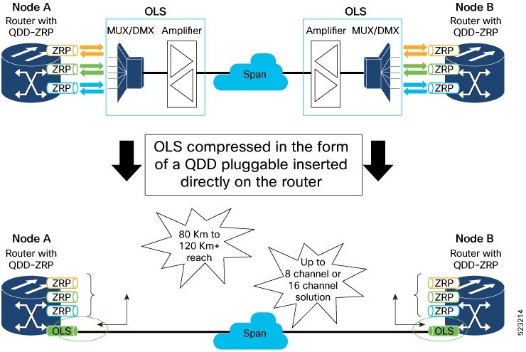
Traditional optical line systems (OLS) require separate chassis-based solutions—such as Cisco NCS 1000 or 2000 Series—with multiplexers/demultiplexers (MUX/DMX) and amplifiers. The QDD optical line system simplifies this model by combining amplification functionality into a QSFP-DD pluggable module, installed directly in compatible router or switch ports, with passive cables providing MUX/DMX capability.

Figure 1. QDD optical line system
Table 1. Feature History Table

Feature Name

Release Information

Description

QDD Optical Line System

Release 25.3.1

The QDD Optical Line System (OLS) is a new pluggable optical amplifier that interconnects two routers or switches for transmitting traffic on a limited number of coherent optical channels over a single span point-to-point link. With the QDD OLS pluggable, it’s now possible to obtain the functionality of amplification into a QSFP-DD module that can be plugged into a port of the line card.

The benefits of this pluggable are:

  • Provides compact solution for amplification.

  • Provides extended reach.

  • Increases fiber bandwidth.

  • Lowers power dissipation.

The feature introduces these changes:
  • CLI:

    • controller ots (QDD OLS)

    • rx-low-threshold

    • tx-low-threshold

    • ampli-control-mode

    • egress-ampli-gain

    • egress-ampli-power

    • egress-ampli-safety-control-mode

    • egress-ampli-osri

    • show controllers ots (QDD OLS)

  • YANG Data Model:

    • Cisco-IOS-XR-controller-ots-oper.yang

    • Cisco-IOS-XR-controller-ots-cfg.yang

    • Cisco-IOS-XR-pmengine-oper.yang

    • Cisco-IOS-XR-pmengine-cfg.yang

    • Cisco-IOS-XR-pmengine-clear-act.yang

Supported hardware for QDD OLS pluggable

These routers and line cards support the QDD OLS pluggable:

  • On Cisco ASR 9912, ASR 9906, and ASR 9922 routers, the QDD optical line system pluggable operates only when installed in the A9K-20HG-FLEX-SE or A9K-8HG-FLEX-SE line cards.

Supported wavelength or frequency configuration

For each channel that uses an ONS-BRK-CS-8LC or ONS-BRK-CS-16LC passive or mux cable, configure the channel’s wavelength or frequency according to the specified operating ranges listed in this table:

Table 2. QDD OLS operating signal wavelength range

Channel Spacing

Total Bandwidth

Wavelength

Frequency

Start End Start End

8 channels - 200 GHz spaced

16 channels - 100 GHz spaced

19.2 nm

2.4 THz

1539.1 nm

1558.4 nm

192.375 THz

194.775 THz

Port mapping for QDD OLS pluggable

The QDD OLS pluggable module includes two main physical ports—COM and Line—each represented by a separate OTS (Optical Transmission Section) controller, known as subport 0 and subport 1. This mapping clarifies which optical ports and signal amplification functions are assigned to each controller.

Port and controller associations

  • The COM port corresponds to subport 0.

  • The Line port corresponds to subport 1.

  • The booster amplifier gain is associated with the Line port (subport 1).

  • The preamplifier gain is associated with the COM port (subport 0).

Each physical port has both RX and TX interfaces, and this table shows how OTS controllers map to the QDD OLS optical ports:
Table 3. Mapping of OTS controller to the optical ports

Controller

Optical Ports

ots R/S/I/P/0

COM-RX (booster input)

COM-TX (preamplifier output)

ots R/S/I/P/1

LINE-RX (preamplifier input)

LINE-TX (booster output)

Use this mapping when configuring or troubleshooting the QDD OLS pluggable to ensure correct controller and port assignment for optical signal management.
This figure hows how the COM side and Line side relate to OTS controllers and optical ports, helping you identify signal flow and controller associations within the module.

Port and controller mapping in QDD OLS pluggable

Configure the operational mode, amplifier gain, and amplifier output power

Set up the operational mode of the OLS pluggable and configure either amplifier gain (gain control mode) or amplifier output power (power control mode) as required for your optical link system.

Use this task to configure an OLS (Optical Line System) pluggable's amplifier settings. Depending on deployment needs, you can enable gain control (to set a specific gain value) or power control (to set an output power value).

Follow these steps to configure the operational mode and amplifier settings for the OLS pluggable:

Before you begin

  • Check that you have the necessary privileges to use the router CLI.

  • Determine the controller identifier for the OLS pluggable (for example, 0/0/2/1/0).

Procedure


Step 1

Configure the amplifier operational mode to manual and set the desired amplifier gain.

Example:

Router#config
Router(config)#controller ots 0/0/2/1/0
Router(config-Ots)#ampli-control-mode manual
Router(config-Ots)#egress-ampli-gain 150
Router(config-Ots)#commit
Router(config-Ots)#exit
Router(config)#exit

Step 2

Configure the amplifier operational mode to powermode and set the desired amplifier output power.

Example:

Router#config
Router(config)#controller ots 0/0/2/1/0
Router(config-Ots)#ampli-control-mode powermode
Router(config-Ots)#egress-ampli-power 50
Router(config-Ots)#commit
Router(config-Ots)#exit
Router(config)#exit

Step 3

Use the show controllers ots command to verify the configuration.

This example shows the controller output after setting the amplifier operational mode to manual and configuring the amplifier gain.

Example:

Router#show controllers ots 0/0/2/1/0

 Controller State: Up 

 Transport Admin State: In Service 

 LED State: Yellow 

         Alarm Status:
         -------------
         Detected Alarms: 
                 RX-LOS-P    

         Alarm Statistics:
         -----------------
         RX-LOS-P = 0          
         RX-LOC = 0          
         TX-POWER-FAIL-LOW = 0          
         INGRESS-AUTO-LASER-SHUT = 0          
         INGRESS-AUTO-POW-RED = 0          
         INGRESS-AMPLI-GAIN-LOW = 0          
         INGRESS-AMPLI-GAIN-HIGH = 0          
         EGRESS-AUTO-LASER-SHUT = 0          
         EGRESS-AUTO-POW-RED = 0          
         EGRESS-AMPLI-GAIN-LOW = 0          
         EGRESS-AMPLI-GAIN-HIGH = 0          
         HIGH-TX-BR-PWR = 0          
         HIGH-RX-BR-PWR = 0          
         SPAN-TOO-SHORT-TX = 0          
         SPAN-TOO-SHORT-RX = 0          

         Parameter Statistics:
         ---------------------
         Total Tx Power = -50.00 dBm 
         Rx Signal Power = -50.00 dBm 
         Tx Signal Power = -50.00 dBm 
         Egress Ampli Gain = 0.0 dB
         Egress Ampli OSRI = OFF 
          
                    
         Configured Parameters:
         -------------
         Egress Ampli Gain = 20.0 dB 
         Egress Ampli Power = 8.0 dBm
         Egress Ampli OSRI = OFF 
         Ampli Control mode = Manual 
         Rx Low Threshold = -20.0 dBm 
         Tx Low Threshold = -5.0 dBm 
          
          
         Temperature = 14.29 Celsius 
         Voltage = 3.37 V 
          
 Optical Module Details
          
         Optics type            : QDD DUAL EDFA
         Name                   : CISCO-ACCELINK
         OUI Number             : 00.00.00
         Part Number            : EDFA-211917-QDD
         Rev Number             : 19
         Serial Number          : ACW2631Z00X
         PID                    : ONS-QDD-OLS=
         Firmware Version       : 1.09
         Date Code(yy/mm/dd)    : 22/06/02
         Fiber Connector Type   : CS 

This example shows the controller output after setting the amplifier operational mode to powermode and configuring the amplifier output power.

Example:

Router#show controllers ots 0/0/2/1/0
Thu Jun  1 08:56:37.236 UTC
 
Controller State: Up
 
Transport Admin State: In Service
 
LED State: Green
 
                Alarm Status:
                -------------
                Detected Alarms: None
 
                Alarm Statistics:
                -----------------
                RX-LOS-P = 4         
                 RX-LOC = 0         
                 TX-POWER-FAIL-LOW = 1         
                 INGRESS-AUTO-LASER-SHUT = 0         
                 INGRESS-AUTO-POW-RED = 0         
                 INGRESS-AMPLI-GAIN-LOW = 0         
                 INGRESS-AMPLI-GAIN-HIGH = 0         
                 EGRESS-AUTO-LASER-SHUT = 0         
                 EGRESS-AUTO-POW-RED = 0         
                 EGRESS-AMPLI-GAIN-LOW = 4         
                 EGRESS-AMPLI-GAIN-HIGH = 1          
                 HIGH-TX-BR-PWR = 0         
                 HIGH-RX-BR-PWR = 0         
                 SPAN-TOO-SHORT-TX = 0         
                 SPAN-TOO-SHORT-RX = 0         
 
                Parameter Statistics:
                ---------------------
                Total Tx Power = 5.00 dBm
                 Rx Signal Power = -22.29 dBm
                 Tx Signal Power = 4.99 dBm
                 Egress Ampli Gain = 3.2 dB
                Egress Ampli OSRI = OFF
 
                 Configured Parameters:
                -------------
                Egress Ampli Gain = 15.0 dB
                 Egress Ampli Power = 5.0 dBm
                Egress Ampli OSRI = OFF
                 Ampli Control mode = Power
                 Rx Low Threshold = -30.0 dBm
                 Tx Low Threshold = -5.0 dBm
  
                Temperature = 29.33 Celsius
                 Voltage = 3.34 V
 
Optical Module Details
 
                Optics type                  : QDD DUAL EDFA
                Name                         : CISCO-II-VI
                OUI Number                   : 00.90.65
                Part Number                  : 60P310001
                Rev Number                   : 01
                Serial Number                : IFB26520001
                PID                          : ONS-QDD-OLS
                VID                          : VES1
                Firmware Version             : 0.10
                Date Code(yy/mm/dd)          : 23/02/22
                Fiber Connector Type         : CS 

The OLS pluggable operates in the selected mode with amplifier parameters applied as configured. Running configuration and controller status commands show the updated operational mode and amplifier values.

Configure the low-threshold power

Set the low-threshold power values (RX or TX) for the optical signal received or transmitted by an OLS pluggable.

Use this task when you need to adjust the OLS pluggable’s sensitivity for detecting low optical signal levels. Configuring these thresholds helps ensure reliable operation by triggering warnings or alarms if signal power falls below the set value.

Follow these steps to configure the low-threshold power:

Before you begin

  • Check that you have the necessary privileges to use the router CLI.

  • Determine the controller identifier for the OLS pluggable (for example, 0/0/2/1/0).

Procedure


Step 1

Configure the optical receive (RX) low power threshold on the OLS pluggable.

Example:

Router#config
Router(config)#controller ots 0/0/2/1/0
Router(config-Ots)#rx-low-threshold -200
Router(config-Ots)#commit
Router(config-Ots)#exit
Router(config)#exit

Note


Use the tx-low-threshold command to set the transmit (TX) low power threshold.

Step 2

Use the show controllers ots command to verify the configuration.

This example shows the controller output after setting the low-threshold power on the OLS pluggable.

Example:

Router#show controllers ots 0/0/2/1/0
Thu Mar 23 21:33:49.862 UTC

Controller State: Up
 
Transport Admin State: In Service
 
LED State: Green
 
                Alarm Status:
                -------------
                Detected Alarms: None
  
                Alarm Statistics:
                -----------------
                RX-LOS-P = 4         
                 RX-LOC = 0         
                 TX-POWER-FAIL-LOW = 1         
                 INGRESS-AUTO-LASER-SHUT = 0         
                 INGRESS-AUTO-POW-RED = 0         
                 INGRESS-AMPLI-GAIN-LOW = 0         
                 INGRESS-AMPLI-GAIN-HIGH = 0         
                 EGRESS-AUTO-LASER-SHUT = 0         
                 EGRESS-AUTO-POW-RED = 0          
                 EGRESS-AMPLI-GAIN-LOW = 4         
                 EGRESS-AMPLI-GAIN-HIGH = 1         
                 HIGH-TX-BR-PWR = 0         
                 HIGH-RX-BR-PWR = 0         
                 SPAN-TOO-SHORT-TX = 0         
                 SPAN-TOO-SHORT-RX = 0         
 
                Parameter Statistics:
                ---------------------
                Total Tx Power = 16.72 dBm
                 Rx Signal Power = -22.29 dBm
                 Tx Signal Power = 16.53 dBm
                 Egress Ampli Gain = 14.7 dB
                Egress Ampli OSRI = OFF
 
                Configured Parameters:
                -------------
                Egress Ampli Gain = 15.0 dB
                 Egress Ampli Power = 4.0 dBm
                Egress Ampli OSRI = OFF
                 Ampli Control mode = Manual
                 Rx Low Threshold = -30.0 dBm
                 Tx Low Threshold = -5.0 dBm
 
 
                Temperature = 27.92 Celsius
                 Voltage = 3.33 V
 
Optical Module Details
 
                Optics type                 : QDD DUAL EDFA
                Name                        : CISCO-II-VI
                OUI Number                  : 00.90.65
                Part Number                 : 60P310001
                Rev Number                  : 01
                Serial Number               : IFB26520001
                PID                         : ONS-QDD-OLS
                VID                         : VES1
                Firmware Version            : 0.10
                Date Code(yy/mm/dd) : 23/02/22
                Fiber Connector Type    : CS

This example shows the controller output after setting the amplifier operational mode to powermode and configuring the amplifier output power.

Example:

Router#show controllers ots 0/0/2/1/0
Thu Jun  1 08:56:37.236 UTC
 
Controller State: Up
 
Transport Admin State: In Service
 
LED State: Green
 
                Alarm Status:
                -------------
                Detected Alarms: None
 
                Alarm Statistics:
                -----------------
                RX-LOS-P = 4         
                 RX-LOC = 0         
                 TX-POWER-FAIL-LOW = 1         
                 INGRESS-AUTO-LASER-SHUT = 0         
                 INGRESS-AUTO-POW-RED = 0         
                 INGRESS-AMPLI-GAIN-LOW = 0         
                 INGRESS-AMPLI-GAIN-HIGH = 0         
                 EGRESS-AUTO-LASER-SHUT = 0         
                 EGRESS-AUTO-POW-RED = 0         
                 EGRESS-AMPLI-GAIN-LOW = 4         
                 EGRESS-AMPLI-GAIN-HIGH = 1          
                 HIGH-TX-BR-PWR = 0         
                 HIGH-RX-BR-PWR = 0         
                 SPAN-TOO-SHORT-TX = 0         
                 SPAN-TOO-SHORT-RX = 0         
 
                Parameter Statistics:
                ---------------------
                Total Tx Power = 5.00 dBm
                 Rx Signal Power = -22.29 dBm
                 Tx Signal Power = 4.99 dBm
                 Egress Ampli Gain = 3.2 dB
                Egress Ampli OSRI = OFF
 
                 Configured Parameters:
                -------------
                Egress Ampli Gain = 15.0 dB
                 Egress Ampli Power = 5.0 dBm
                Egress Ampli OSRI = OFF
                 Ampli Control mode = Power
                 Rx Low Threshold = -30.0 dBm
                 Tx Low Threshold = -5.0 dBm
  
                Temperature = 29.33 Celsius
                 Voltage = 3.34 V
 
Optical Module Details
 
                Optics type                  : QDD DUAL EDFA
                Name                         : CISCO-II-VI
                OUI Number                   : 00.90.65
                Part Number                  : 60P310001
                Rev Number                   : 01
                Serial Number                : IFB26520001
                PID                          : ONS-QDD-OLS
                VID                          : VES1
                Firmware Version             : 0.10
                Date Code(yy/mm/dd)          : 23/02/22
                Fiber Connector Type         : CS 

The specified RX and/or TX low-threshold power settings are applied to the OLS pluggable controller. The router will monitor for low signal conditions based on the configured thresholds.

Configure the optical safety remote interlock (OSRI)

Ensure safety and proper maintenance by configuring the Optical Safety Remote Interlock (OSRI) on an OLS pluggable. OSRI enables safe shutdown of the amplifier during maintenance, debugging, or when the OLS pluggable is not in use.

The OSRI configuration limits the output power of the amplifier based on the input power when enabled. This safety mechanism protects both equipment and personnel during specific scenarios. With OSRI enabled, the output power can be a maximum of -15 dBm, based on the input power.

Follow these steps to configure the optical safety remote interlock (OSRI):

Before you begin

  • Check that you have the necessary privileges to use the router CLI.

  • Determine the controller identifier for the OLS pluggable (for example, 0/0/2/1/0).

  • Plan a maintenance window, if necessary, to avoid service disruption.

Procedure


Step 1

Enable the egress amplifier OSRI.

Example:

Router#config
Router(config)#controller ots 0/0/2/1/0
Router(config-Ots)#egress-ampli-osri on
Router(config-Ots)#commit
Router(config-Ots)#exit
Router(config)#exit

Step 2

Use the show controllers ots command to verify the configuration.

Example:

Router#show controllers ots 0/0/2/1/0

Thu Jun  1 09:04:10.335 UTC
 
Controller State: Up
 
Transport Admin State: In Service
 
LED State: Green
 
                Alarm Status:
                -------------
                Detected Alarms: None
  
                Alarm Statistics:
                -----------------
                RX-LOS-P = 4         
                 RX-LOC = 0         
                 TX-POWER-FAIL-LOW = 1         
                 INGRESS-AUTO-LASER-SHUT = 0         
                 INGRESS-AUTO-POW-RED = 0         
                 INGRESS-AMPLI-GAIN-LOW = 0         
                 INGRESS-AMPLI-GAIN-HIGH = 0         
                 EGRESS-AUTO-LASER-SHUT = 0         
                 EGRESS-AUTO-POW-RED = 0         
                 EGRESS-AMPLI-GAIN-LOW = 4         
                 EGRESS-AMPLI-GAIN-HIGH = 1         
                 HIGH-TX-BR-PWR = 0         
                 HIGH-RX-BR-PWR = 0         
                 SPAN-TOO-SHORT-TX = 0         
                 SPAN-TOO-SHORT-RX = 0         
 
                Parameter Statistics:
                ---------------------
                Total Tx Power = -50.00 dBm
                 Rx Signal Power = -22.36 dBm
                 Tx Signal Power = -50.00 dBm
                 Egress Ampli Gain = 0.0 dB
                Egress Ampli OSRI = ON
 
                Configured Parameters:
                -------------
                Egress Ampli Gain = 15.0 dB
                 Egress Ampli Power = 5.0 dBm
                Egress Ampli OSRI = ON
                 Ampli Control mode = Power
                 Rx Low Threshold = -30.0 dBm
                 Tx Low Threshold = -5.0 dBm
 
                Temperature = 27.90 Celsius
                 Voltage = 3.34 V
 
Optical Module Details
 
                Optics type                     : QDD DUAL EDFA
                Name                            : CISCO-II-VI
                OUI Number                      : 00.90.65
                Part Number                     : 60P310001
                Rev Number                      : 01
                Serial Number                   : IFB26520001
                PID                             : ONS-QDD-OLS
                VID                             : VES1
                Firmware Version                : 0.10
                Date Code(yy/mm/dd)             : 23/02/22
                Fiber Connector Type            : CS
 

The optical safety remote interlock (OSRI) is enabled on the OLS pluggable. The amplifier output power is now limited for safe handling during maintenance and debugging.

Configure safety control mode

Enable safety control mode on subport 1 of an OLS (Optical Line System) pluggable to automatically manage signal output power and trigger safety alarms under specified conditions.

Safety control mode ensures laser safety. If you set the safety control mode to auto, and a loss of signal (LOS) is detected on the line RX, the system automatically normalizes the line TX signal output power to 8 dBm and activates the ALS (Automatic Laser Shutdown) and APR (Automatic Power Reduction) alarms.

Follow these steps to configure the safety control mode for the OLS pluggable:

Before you begin

  • Check that you have the necessary privileges to use the router CLI.

  • Determine the controller identifier for the OLS pluggable (for example, 0/0/2/1/0).

  • Identify the correct OTS (Optical Transport Section) controller and the relevant subport (must be subport 1).

Procedure


Step 1

Enable safety control mode on the OLS pluggable (on subport 1):

Example:

Router#config
Router(config)#controller ots 0/0/2/1/1
Router(config-Ots)#egress-ampli-safety-control-mode auto
Router(config-Ots)#commit
Router(config-Ots)#exit
Router(config)#exit

Step 2

Use the show controllers ots command to verify the configuration.

This example shows the controller output after enabling the safety control mode.

Example:

Router#show controllers ots 0/0/2/1/1

Controller State: Down
 
Transport Admin State: In Service
 
LED State: Yellow
 
                Alarm Status:
                -------------
                Detected Alarms:
                                 RX-LOS-P   
                                 EGRESS-AUTO-LASER-SHUT   
                                 EGRESS-AUTO-POW-RED   
                                 EGRESS-AMPLI-GAIN-HIGH   
 
                Alarm Statistics:
                -----------------
                RX-LOS-P = 12        
                 RX-LOC = 0         
                 TX-POWER-FAIL-LOW = 1         
                 INGRESS-AUTO-LASER-SHUT = 0         
                 INGRESS-AUTO-POW-RED = 0         
                 INGRESS-AMPLI-GAIN-LOW = 0         
                 INGRESS-AMPLI-GAIN-HIGH = 0         
                 EGRESS-AUTO-LASER-SHUT = 13        
                 EGRESS-AUTO-POW-RED = 13        
                 EGRESS-AMPLI-GAIN-LOW = 2         
                 EGRESS-AMPLI-GAIN-HIGH = 12        
                 HIGH-TX-BR-PWR = 0         
                 HIGH-RX-BR-PWR = 0         
                 SPAN-TOO-SHORT-TX = 0         
                 SPAN-TOO-SHORT-RX = 0         
 
                Parameter Statistics:
                ---------------------
                Total Tx Power = 8.08 dBm
                 Rx Signal Power = -50.00 dBm
                 Tx Signal Power = 5.61 dBm
                 Egress Ampli Gain = 28.9 dB
                Egress Ampli Safety Control mode = auto
                 Egress Ampli OSRI = OFF


                Configured Parameters:
                -------------
                Egress Ampli Gain = 23.0 dB
                 Egress Ampli Power = 3.0 dBm
                Egress Ampli Safety Control mode = auto
                 Egress Ampli OSRI = OFF
                 Ampli Control mode = Manual
                 Rx Low Threshold = -30.0 dBm
                 Tx Low Threshold = -5.0 dBm
 
 
                Temperature = 23.00 Celsius
                 Voltage = 3.36 V
 
Optical Module Details
 
                Optics type                     : QDD DUAL EDFA
                Name                            : CISCO-ACCELINK
                OUI Number                      : 00.00.00
                Part Number                     : EDFA-211917-QDD
                Rev Number                      : 24
                Serial Number                   : ACW2651Z001
                PID                             : ONS-QDD-OLS
                VID                             : VES1
                Firmware Version                : 2.04
                Date Code(yy/mm/dd)             : 22/12/27
                Fiber Connector Type            : CS
   

Safety control mode is enabled on subport 1 of the selected OLS pluggable. If LOS is detected on the line RX, the system will automatically normalize the TX output power to 8 dBm and trigger the ALS (automatic laser shutdown) and APR (automatic power reduction) safety alarms.

Use case for QDD OLS pluggable

The QDD OLS pluggable can transport 8 or 16 coherent optical channels from the DWDM optical modules that are plugged into the router.

The optical modules are interconnected with the QDD OLS amplifiers using the following cables:

  • ONS-BRK-CS-8LC: dual fanout 1x8 cable-assembly with embedded passive splitter and coupler

  • ONS-BRK-CS-16LC: dual fanout 1x16 cable-assembly with embedded passive splitter and coupler

  • ONS-CAB-CS-LC-5: dual adapter patch-cord CS-connector to LC-connector

This section explains the 8-channel Optical Line System (OLS) that is achieved by using the QDD OLS pluggable and QDD-400G-ZRP-S modules. With this 8-channel Optical Line System (OLS) set-up it’s now possible to obtain 28 dB/112 kilometer span reach. Also, the fiber bandwidth is increased by 8 times.

Components and interconnections for the 8-channel optical line system

The 8-channel optical line system (OLS) is implemented using QDD OLS pluggables and QDD-400G-ZRP-S modules, enabling a span reach of up to 28 dB/112 kilometers and increasing fiber bandwidth by eight times. These sections list the required components and describe the interconnections needed for system configuration.

Hardware components

  • Routers: Four Cisco ASR 9912 (designated as Node A, Node B, Node C, and Node D)

  • Line Cards (LCs): Four A9K-20HG-FLEX-SE

  • Pluggable Optical Modules: Sixteen QDD-400G-ZRP-S or sixteen DP01QS28-E20/DP01QS28-E25 modules

  • OLS Pluggables: Two QDD OLS (ONS-QDD-OLS) pluggables

  • Breakout Cables: Two ONS-BRK-CS-8LC breakout cables

  • Fiber Optic Cables: Two ONS-CAB-CS-LC-5 fiber optic cables

Node-specific connections

This section provides connection details on each node.

  • Node A

    • Insert two A9K-20HG-FLEX-SE line cards into the Cisco ASR 9912 router.

    • Insert four QDD-400G-ZRP-S modules into ports 0 and 2 of the line cards.

    • Insert one QDD OLS (ONS-QDD-OLS) pluggable into port 3 of the line card.

  • Node B

    • Insert two A9K-20HG-FLEX-SE line cards into the Cisco ASR 9912 router.

    • Insert four QDD-400G-ZRP-S modules into ports 0 and 2 of the line cards.

  • Node C

    • Insert two A9K-20HG-FLEX-SE line cards into the Cisco ASR 9912 router.

    • Insert four QDD-400G-ZRP-S modules into ports 0 and 2 of the line cards.

  • Node D

    • Insert two A9K-20HG-FLEX-SE line cards into the Cisco ASR 9912 router.

    • Insert four QDD-400G-ZRP-S modules into ports 0 and 2 of the line cards.

    • Insert one QDD OLS (ONS-QDD-OLS) pluggable into port 3 of the line card.

Interconnections

This section provides connection details between nodes.

  • Between Node A and Node B:

    Use an ONS-BRK-CS-8LC breakout cable to connect eight QDD-400G-ZRP-S modules (four from each node) and the QDD OLS (ONS-QDD-OLS) pluggable at port 3 of Node A.
  • Between Node C and Node D:

    Use another ONS-BRK-CS-8LC breakout cable to connect eight QDD-400G-ZRP-S modules (four from each node) and the QDD OLS (ONS-QDD-OLS) pluggable at port 3 of Node D.
  • Between Node A and Node D:

    Use an ONS-CAB-CS-LC-5 fiber optic cable to connect the QDD OLS (ONS-QDD-OLS) pluggables in Node A and Node D.

For complete connection details and topology, refer to this block diagram.

Figure 2. 8-channel optical line system

Troubleshooting actions for OLS alarms

This section provides reference procedures to identify, understand, and clear common OLS (Optical Line System) alarms. Each alarm includes its default severity, logical object, a description of the alarm condition, and step-by-step troubleshooting actions.

RX-LOS-P

The RX-LOS-P alarm is raised when there is loss of signal.

  • Default severity: Critical

  • Logical object: Controller

To clear the RX-LOS-P alarm:

  1. Verify the transmission (TX) at the peer end.

  2. Check the fiber connections.

If the alarm does not clear, visit the Cisco Technical Support Website at http://www.cisco.com/c/en/us/support/index.html or contact Cisco TAC (1 800 553-2447).

RX-POWER-FAIL-LOW

The RX-POWER-FAIL-LOW alarm is raised when the RX power is below the configured low threshold values.

  • Default severity: Minor (MN), Non-Service-Affecting (NSA)

  • Logical object: Controller

To clear the RX-LOS-P alarm:

  1. Verify the transmission (TX) at the peer end.

  2. Check the fiber connections.

  3. Increase the peer end gain or transmit-power value to obtain the RX power above the threshold.

If the alarm does not clear, visit the Cisco Technical Support Website at http://www.cisco.com/c/en/us/support/index.html or contact Cisco TAC (1 800 553-2447).

TX-POWER-FAIL-LOW

The TX-POWER-FAIL-LOW alarm is raised when the TX power is below the configured low threshold values.

  • Default severity: Critical

  • Logical object: Controller

To clear the TX-POWER-FAIL-LOW alarm:

  1. Increase the gain or power configuration value to obtain the TX power above the threshold.

If the alarm does not clear, visit the Cisco Technical Support Website at http://www.cisco.com/c/en/us/support/index.html or contact Cisco TAC (1 800 553-2447).

EGRESS-AMPLI-GAIN-LOW

The EGRESS-AMPLI-GAIN-LOW alarm is raised when the actual gain of the OLS pluggable is lower than the configured gain value.

  • Default severity: Minor (MN), Non-Service-Affecting (NSA)

  • Logical object: Controller

To clear the EGRESS-AMPLI-GAIN-LOW alarm:

  1. Configure the gain value within the optimum range.

If the alarm does not clear, visit the Cisco Technical Support Website at http://www.cisco.com/c/en/us/support/index.html or contact Cisco TAC (1 800 553-2447).

EGRESS-AMPLI-GAIN-HIGH

The EGRESS-AMPLI-GAIN-HIGH alarm is raised when the actual gain of the OLS pluggable is higher than the configured gain value.

  • Default severity: Minor (MN), Non-Service-Affecting (NSA)

  • Logical object: Controller

To clear the EGRESS-AMPLI-GAIN-HIGH alarm:

  1. Verify the RX and TX values and adjust the gain within the optimum working range.

If the alarm does not clear, visit the Cisco Technical Support Website at http://www.cisco.com/c/en/us/support/index.html or contact Cisco TAC (1 800 553-2447).

EGRESS-AUTO-LASER-SHUT

The EGRESS-AUTO-LASER-SHUT alarm is raised when there is loss of signal (LOS) on the OTS line side (subport 1).

  • Default severity: Not alarmed

  • Logical object: Controller

To clear the EGRESS-AUTO-LASER-SHUT alarm:

  1. Verify the fiber connections on the line side of the OLS pluggable.

  2. Verify the gain or power on the line side of the peer end.

If the alarm does not clear, visit the Cisco Technical Support Website at http://www.cisco.com/c/en/us/support/index.html or contact Cisco TAC (1 800 553-2447).

EGRESS-AUTO-POW-RED

The EGRESS-AUTO-POW-RED alarm is raised when there is loss of signal (LOS) on the OTS line side (subport 1).

  • Default severity: Not alarmed

  • Logical object: Controller

To clear the EGRESS-AUTO-POW-RED alarm:

  1. Verify the fiber connections on the line side of the OLS pluggable.

  2. Verify the gain or power on the line side of the peer end.

If the alarm does not clear, visit the Cisco Technical Support Website at http://www.cisco.com/c/en/us/support/index.html or contact Cisco TAC (1 800 553-2447).


Note


Contact Cisco TAC for alarms not listed here or for further assistance with persistent alarm conditions.